Germany
Headquarters
Australia
Austria
Belgium
Brazil
Bulgaria
China
Czech
Republic
Denmark
France
Greece
Hungary
India
Ireland
ROTHENBERGER AG
Industriestrasse 7 • D-65779 Kelkheim/Germany
Tel. + 49 (0) 61 95 / 800 - 1 • Fax + 49 (0) 61 95 / 7 44 22
verkauf@rothenberger.com • www.rothenberger.com
ROTHENBERGER Produktion GmbH
Lilienthalstrasse 71 - 87 • D-37235 Hessisch-Lichtenau
Tel. + 49 (0) 56 02 / 93 94 - 0 • Fax + 49 (0) 56 02 / 93 94 36
ROTHENBERGER Werkzeuge GmbH
Industriestrasse 7 • D-65779 Kelkheim/Germany
Tel. + 49 (0) 61 95 / 800 - 1 • Fax + 49 (0) 61 95 / 7 44 22
verkauf@rothenberger.com
ROTHENBERGER Australia Pty. Ltd.
Unit 12 • 5 Hudson Avenue • Castle Hill • N.S.W. 2154
Tel. + 61 2 / 98 99 75 77 • Fax + 61 2 / 98 99 76 77
rothenberger@rothenberger.com.au
www.rothenberger.com.au
ROTHENBERGER Werkzeuge- und Maschinen Handelsgesellschaft m.b.H.
Gewerbeparkstrasse 9 • A-5081 Anif near Salzburg
Tel. + 43 (0) 62 46 / 7 20 91-45 •
Fax + 43 (0) 62 46 / 7 20 91 -15
office@rothenberger.at • www.rothenberger.at
ROTHENBERGER Benelux bvba
Antwerpsesteenweg 59 • B-2630 Aartselaar
Tel. + 32 (0) 3 / 8 77 22 77 • Fax + 32 (0) 3 / 8 77 03 94
info@rothenberger.be
ROTHENBERGER do Brasil Ltda.
Rua marinho de Carvalho, No. 72 - Vila Marina
09921-005 Diadema - Sao Paulo - Brazil
Tel. + 55 11 / 40 44 47-48 • Fax + 55 11 / 40 44 50-51
vendas@rothenberger.com.br • www.rothenberger.com.br
ROTHENBERGER Bulgaria GmbH
Boul. Sitniakovo 79 • BG-1111 Sofia
Tel. + 35 9 / 2 9 46 14 59 • Fax + 35 9 / 2 9 46 12 05
info@rothenberger.bg • www.rothenberger.bg
SHANGHAI ROTHENBERGER I/E CO., LTD
No. 199 Jiugan Road, Sijing Town
Songjiang District, Shanghai, (201601) China
Tel. + 86 / 21 57 61 76 88 • 0086 / 21 5761 7959
Fax + 86 / 21 57 62 60 62 • office@rothenberger.cn
ROTHENBERGER CZ, nárˇadí a stroje, spol. s.r.o.
Vinohradská 100 (1710) • CZ-130 00 Praha 3
Tel. + 42 02 / 71 73 01 83 • Fax + 42 02 / 67 31 01 87
info@rothenberger.cz • www.rothenberger.cz
ROTHENBERGER Scandinavia A/S
Fåborgvej 8 • DK-9220 Aalborg Øst
Tel. + 45 98 / 15 75 66 • Fax + 45 98 / 15 68 23
roscan@rothenberger.dk
ROTHENBERGER France S.A.
24, rue des Drapiers, BP 45033 • F-57071 Metz Cedex 3
Tel. + 33 3 / 87 74 92 92 • Fax + 33 3 / 87 74 94 03
info-fr@rothenberger.com
ROTHENBERGER Hellas S.A.
249 Syngrou Avenue • GR-171 22 Nea Smyrni, Athens
Tel. + 30 210 / 94 07 302 • Fax + 30 210 / 94 07 322
ROTHENBERGER Hungary Kft.
Gubacsi út 26 • H-1097 Budapest
Tel. + 36 1 / 3 47 - 50 40 • Fax + 36 1 / 3 47 - 50 59
mail@rothenberger.hu
ROTHENBERGER India Private Limited
B-1/D-5,Ground Floor
Mohan Cooperative Industrial Estate
Mathura Road, New Delhi 110044
Tel. + 91 11 / 51 69 90 40, 51 69 90 50 • Fax + 91 11 / 51 69 90 30
ROTHENBERGER Ireland Ltd.
Bay N. 119, Shannon Industrial Estate
IRL-Shannon, Co. Clare
Tel. + 35 3 61 / 47 21 88 • Fax + 35 3 61 / 47 24 36
ROTHENBERGER Worldwide
Italy
Mexico
Netherlands
Poland
Portugal
Singapore
South Africa
Spain
Switzerland
Turkey
UK
USA
Russia
ROTHENBERGER Italiana s.r.l.
Via G. Reiss Romoli 17 • I-20019 Settimo Milanese
Tel. + 39 02 / 33 50 12 12 • Fax + 39 02 / 33 50 0151
rothenberger@rothenberger.it • www.rothenberger.it
Rothenberger S.A. Sucursal México
Bosques de Duraznos No. 69-1006
Bosques de las Lomas • México D.F. 11700
Tel. + 52 / 55 85 89 - 39 48 ext 21/22
Fax + 52 / 55 85 89 - 57 70 ext 11
ROTHENBERGER Nederland bv
Postbus 45 • NL-5120 AA Rijen
Tel. + 31 (0) 1 61 / 29 35 79 • Fax + 31 (0) 1 61 / 29 39 08
info@rothenberger.nl • www.rothenberger.nl
ROTHENBERGER Polska Sp.z.o.o.
ul. Cyklamenów 1 • PL-04-798 Warszawa
Tel. + 48 22 / 6 12 77 01 • Fax + 48 22 / 6 12 72 95
biuro@rothenberger.pl • www.rothenberger.pl
SUPER-EGO TOOLS FERRAMENTAS, S.A.
Apartado 62 - 2894-909 Alcochete - PORTUGAL
Tel. + 3 51 / 9 12 21 80 80 • Fax + 3 51 / 2 26 00 40 30
sul.pt@rothenberger.es
ROTHENBERGER TOOLS (FE) PTE LTD
147 Thyrwhitt Road
Singapore 207561
Tel. + 65 / 6296 - 2031 • Fax + 65 / 6296 - 4031
www.rothenberger.com.sg
ROTHENBERGER-TOOLS SA (PTY) Ltd.
P.O. Box 4360 • Edenvale 1610
165 Vanderbijl Street, Meadowdale Germiston
Gauteng (Johannesburg), South Africa
Tel. + 27 11 / 3 72 96 33 • Fax + 27 11 / 3 72 96 32
ROTHENBERGER S.A.
Ctra. Durango-Elorrio, Km 2 • E-48220 Abadiano (Vizcaya)
(P.O. Box) 117 • E-48200 Durango (Vizcaya)
Tel. + 34 94 / 6 21 01 00 • Fax + 34 94 / 6 21 01 31
export@rothenberger.es • www.rothenberger.es
ROTHENBERGER Schweiz AG
Herostr. 9 • CH-8048 Zürich
Tel. + 41 / 14 01 08 00 • Fax + 41 / 1 4 01 06 08
ROTHENBERGER Tes. Alet ve Mak. San. Tic. Ltd. Sti
Poyraz Sok. No: 20/3 - Detay Is Merkezi
TR-34722 Kadiköy-Istanbul
Tel. + 90 / 216 449 24 85 pbx • Fax + 90 / 216 449 24 85
rothenberger@rothenberger.com.tr
ROTHENBERGER UK Limited
2, Kingsthorne Park, Henson Way
Kettering • GB-Northants NN16 8PX
Tel. + 44 15 36 / 31 03 00 • Fax + 44 15 36 / 31 06 00
info@rothenberger.co.uk
ROTHENBERGER USA LLC
4455 Boeing Drive; USA-Rockford, IL 61109
Tel. + 1 / 8 15 3 97 70 70 • Fax + 1 / 8 15 3 97 82 89
www.rothenberger-usa.com
ROTHENBERGER USA Inc.
Western Regional Office • USA-955 Monterey Pass Road
Monterey Park, CA 91754
Tel. + 13 23 / 2 68 13 81 • Fax + 13 23 / 26 04 97
ROTHENBERGER Agency
OLMAX
2-d Verkhny Mikhailovsky pr-d, 9 build.2
115419 Moscow
Tel. +7/09 57 92 59 44 • Fax +7/09 57 92 59 46
Service Hotline +49 (0) 61 95-99 52-12
www.rothenberger.com
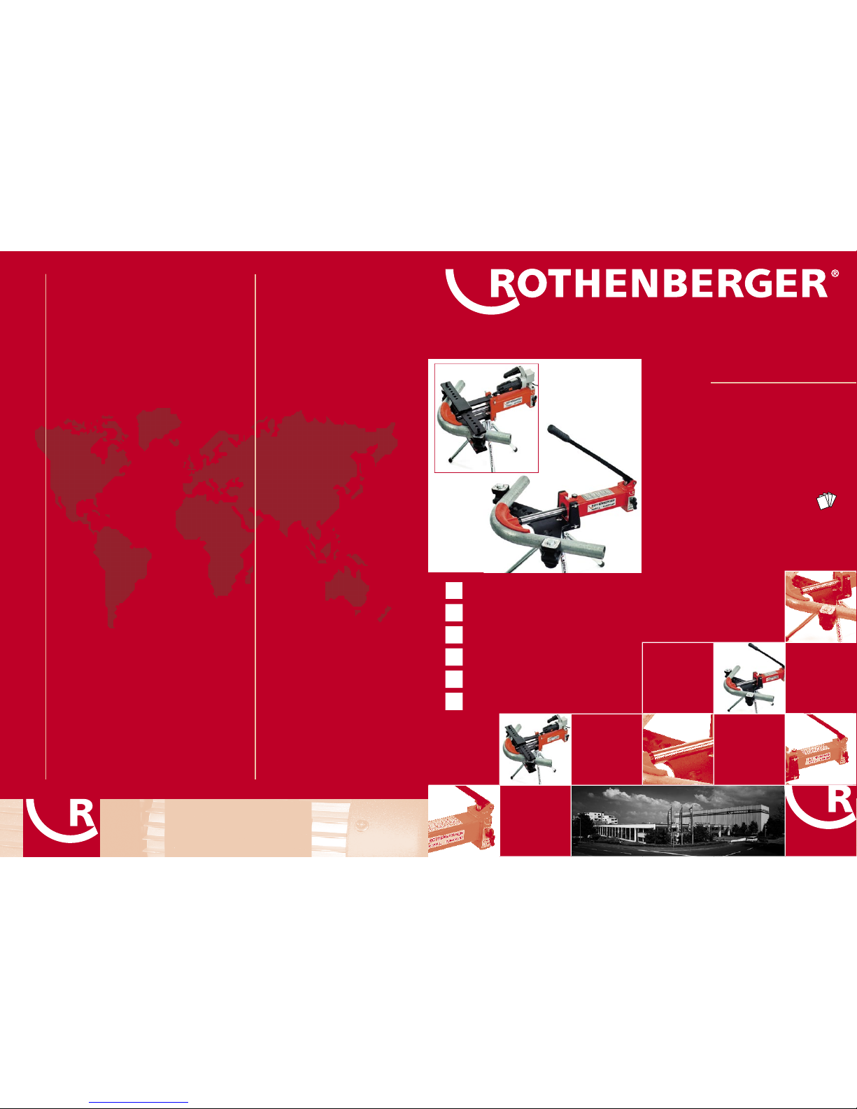
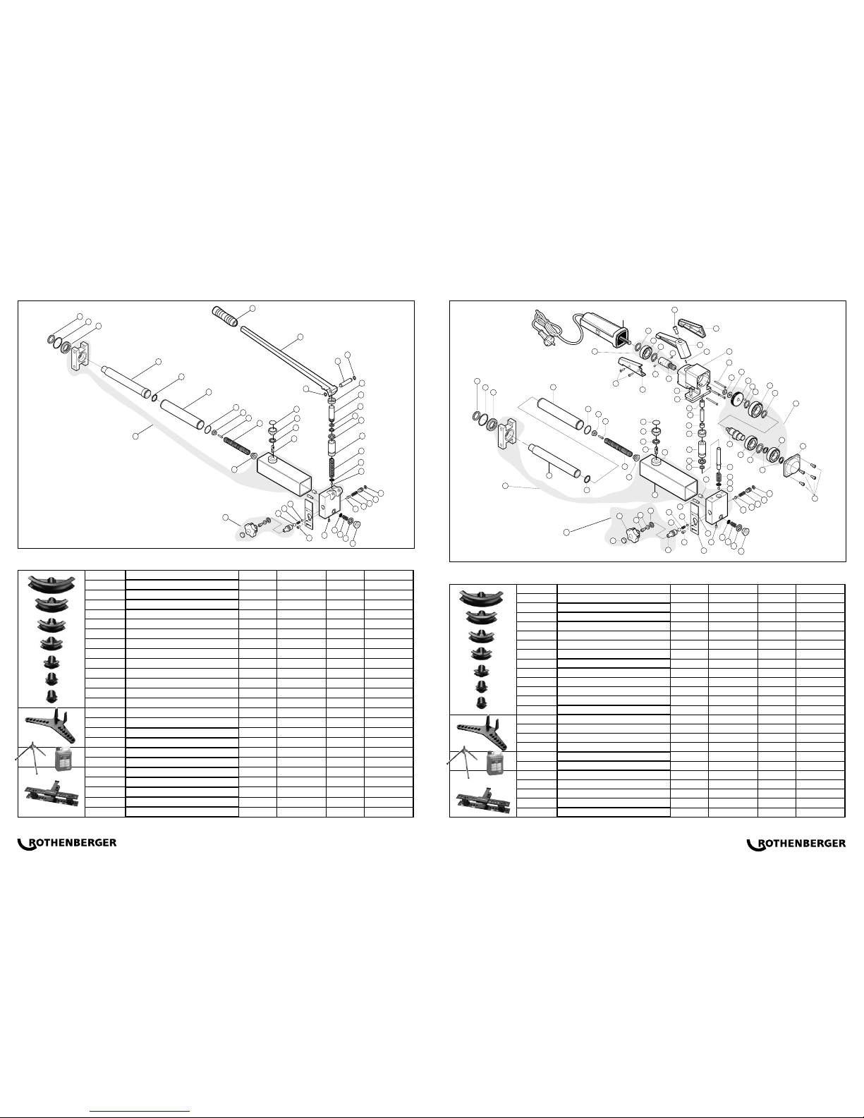
ROBULL 2"
Bedienungsanleitung
Instructions for use
Instruction d'utilisation
Instrucciones de uso
Istruzioni d'uso
Instruções de uso
www.rothenberger.com/manuals
5.7950X
5.7966X
5.7961X
5.7969X
5.7973X
5.7972X
9992079 02.08