Scotchman 9012-24M User manual

You have downloaded a manual for our
Model 9012-24M Ironworker.
This manual does not include all of the
optional tooling for this machine.
If you would like a tooling manual,
please download our #40 Tooling Manual.
WARNING
SAFETY GLASSES REQUIRED WHEN
OPERATING OR OBSERVING THIS MACHINE
NEVER-
NEVER-
NEVER-
NEVER-
NEVER-
NEVER-
NEVER-
TO PREVENT SERIOUS BODILY INJURY
Operate, install tooling, service or adjust machine without
operator's manual and safety film.
Service machine with electrical power connected.
Operate any station without the respective strippers or
Operate machine with protective guards removed.
Place any part of your body under blade, punch or moving
Operate punch station without checking the punch to die
alignment and tightness.
Punch half holes, punch or shear unknown materials, side load
DO NOT REMOVE THIS SIGN FROM THIS MACHINE
REV. 0310
FOR MORE INFORMATION CONTACT SCOTCHMAN INDUSTRIES INC.
1-800-843-8844
003100
proper instructions and without reading and understanding the
hold-downs in place.
members.
(Check alignment and tightness daily.)
press brakes.
AT
LUBRICATE
BEFORE
OPERATING
19103 0481
LUBRICATE
BEFORE
OPERATING
19103 0481
3120 0389
DANGER
SERIAL
SCOTCHMAN INDUSTRIES, INC.
PHILIP, SOUTH DAKOTA, U.S.A.
MADE IN U.S.A.
MODEL
FLA
HZ
PH
H.P. VOLT
BLADE LENGTH
PH. 605-859-2542
PSI
DO NOT EXCEED
3 X 3 X 1/4
WHEN MITERING
0502003195
JOG
START STOP
RUN
JOG
START
SHEAR
PUNCH
PROBE
004085
9012-24M
MACHINE CAPACITIES
SPEC. BASED ON MILD STEEL-65,000 PSI TENSILE
PUNCH PUNCH
STROKE
FLAT SHEAR ANGLE SHEAR
90 TONS
Ø27 THRU 25MM
Ø1-1/16 THRU 1" 2.25" - 57MM
12" - 300MM
150X150X12MM
6"X6"X 1/2"
25X200 - 6X600MM
1X8 - 1/4X 24"
BLADE LENGTH 24" - 600MM
#019139 5,03
THROAT DEPTH

www.scotchman.com
MODEL
9012-24M
IRONWORKER
SCOTCHMAN INDS. - 180 E. HWY 14 - PO BOX 850 - PHILIP, SD 57567 PHONE: 1-800-843-8844
PRINTED SEPTEMBER 2021

Page 2
TABLE OF CONTENTS
SECTION DESCRIPTION PAGE #
1.0 INTRODUCTION 4
2.0 SAFETY PRECAUTIONS 4
2.1 WARRANTY 5
3.0 WARNING LABELS 8-9
4.0 INSTALLATION & SET-UP 10-19
4.1 Physical Dimensions 10
4.2 Machine Moving Procedures 12
4.3 Physical Inspections 13
4.4 Electrical Requirements 14
4.5 Machine Start Up 14
4.6 Machine Stroke Inspection & Adjustment 18
5.0 MAINTENANCE 20-23
5.1 Lubrication 20
5.2 Routine Lubrication 20
5.3 Scheduled Maintenance 22
6.0 MACHINE OPERATION 24-34
6.1 Punch Operation 24
6.1B Stripper Adjustment 28
6.2 Bar Shear Operation 29
6.2A Shear Arm Adjustment 30
6.2B Shear Blade Adjustment 32
7.0 OPTIONAL TOOL OPERATION 35-59
7.1 6 x 6 Angle Shear 35
7.2 Rod Shear 38

Page 3
TABLE OF CONTENTS
SECTION DESCRIPTION PAGE #
7.3 6 x 6 Ninety Degree Notcher 40
7.4 Rectangle Notcher 42
7.5 Brakes 44
7.6 Angle Iron Brake 46
7.7 Channel Shear 48
7.8 Pipe Notcher 50
7.9 Picket Tool 52
7.10 Square Tube Shear 54
7.11 Optional Punch and Die Holders 56
7.11A 2-1/2" & 3" Die Inserts 56
7.11B Offset Die Holder 56
7.11C 6 x 6 Die Holder 56
7.11D # 45 Punch Retaining Nut 56
7.11E Heavy Duty Split Ring Retaining Nut 56
7.12 Optional Gauging Equipment 58
7.12A 48 Inch Deluxe Back Gauge 58
7.13 Urethane Stripper 59
7.14 Weld Coupon Bender Tool 64
7.15 Multi-Shear Tool 66
8.0 TROUBLE SHOOTING GUIDE 68-71
8.1 Electrical Trouble Shooting-Motor 68
8.2 Limit Switch Inspection 69
8.3 Control Valve Inspection 69
8.4 Hydraulics 70
8.5 Cylinder Seal Replacement 70

Page 4
TABLE OF CONTENTS
SECTION DESCRIPTION PAGE #
9.0 IRONWORKER PARTS LISTS 72-93
9.1 Shear Arm Assembly 72
9.2 Punch Assembly 74
9.3 Stripper Assembly 76
9.4 Urethane Stripper 78
9.5 Upper Arm Assembly 80
9.6 Stroke Control Assembly 82
9.7 Hold Down Assembly 84
9.8 Cylinder Assembly 86
9.9 Connecting Link Assembly 87
9.10 Power Unit - Serial # 20661 & Up 88
9.11 Electrical Unit 90
9.12 Standard Die Holder w/Inserts 93
9.13 Punch Retaining Nuts 94
10.0 SUPPLEMENT FOR OLDER MODELS 95-99

Page 5
The Scotchman 9012-24M is a versatile, multi-purpose, shearing, punching and forming machine
engineered for trouble free operation. The design of the machine combines simplicity of operation with
smooth, full stroke control. The ability of the operator to control the machine’s direction of movement at
any point in the stroke (stop, jog or reverse) gives the Scotchman 9012-24M Ironworker a tremendous
advantage over mechanical ironworkers. There is no chance of the Scotchman being "accidentally
tripped". The hydraulic system operates at a maximum pressure of 2,650 PSI (183 BAR) and is protected
from overload by a pilot operated relief valve. The Scotchman 9012-24M Ironworker lends itself to a
variety of special purpose tools that can be mounted on the tool table where a selection of power and
stroke potentials are available.
1.0 INTRODUCTION

Page 6
2.0 SAFETY PRECAUTIONS
1) The operators of this machine must be qualified and well trained in the operation of the machine.
The operators must be aware of the capacities of the machine and the proper use of the hold down
devices, strippers and guards provided with the machine.
2) All of the guards, adjustable restrictors and awareness barriers must be installed on the machine
and kept in good working order. Promptly replace worn or damaged parts with authorized parts.
3) Never place any part of your body into or under any of the machine’s moving parts, strippers or
hold devices.
4) Wear the appropriate personal protective equipment. Safety glasses are required at all times,
whether operating, setting up or observing this machine in operation. Since heavy pieces of metal
with sharp edges can be processed on this machine, the operator should also wear steel-toed shoes
and tight fitting leather gloves.
5) Strictly comply with all warning labels and decals on the machine. Never remove any of the
labels. Replace worn or damaged labels promptly.
6) Always disconnect and lock out the power when performing maintenance work or setting up any
tooling on the machine. Follow the procedures outlined in the operator’s manual for setting up,
changing or aligning any tooling on this machine.
7) Never operate this machine with dull or damaged tooling. Replace worn punches, dies and blades
promptly.
8) Practice good housekeeping. Keep the area around the machine clear and well lit. Do not
obstruct the operator’s position by placing anything around the machine that would impede the
operator’s access to the machine.
9) Never modify this machine in any way without the written permission of the manufacturer.
10) Never leave this machine running unattended.
11) Always operate the punch station facing the station, standing. Never operate any of the work
stations from a sitting or kneeling position.
12) Set up a program of routine inspections and maintenance for this machine. Make all repairs and
adjustments in accordance with the manufacturer’s instructions.
13) A safety DVD was mailed to you or shipped with the machine. If you did not receive it,
please contact the factory or your local dealer immediately and one will be sent to you at no
charge. If this machine was purchased used, please contact the factory for a safety DVD.

Page 7
2.1 WARRANTY
Scotchman Industries Inc. will, within three years of date of purchase, replace F.O.B. the factory or
refund the purchase price for any goods which are defective in materials or workmanship, provided that
the buyer returns the warranty registration card within thirty days of the purchase date and, at the
seller’s option, returns the defective goods freight and delivery prepaid to the seller, which shall be the
buyer’s sole and exclusive remedy for defective goods.
Hydraulic and electrical components are subject to their respective manufacturer’s warranties.
This warranty does not apply to machines and/or components which have been altered, changed or
modified in any way or subjected to abusive and abnormal use, inadequate maintenance and lubrication
or subjected to use beyond the seller’s recommended capacities and specifications.
In no event shall seller be liable for labor cost expended on such goods or consequential damages.
The seller shall not be liable to purchaser or any other person for loss or damage directly or indirectly
arising from the use of the goods or from any other cause.
No officer, employee or agent of the seller is authorized to make any oral representations or warranty of
fitness or to waive any of the foregoing terms of sale and none shall be binding on the seller.
Any electrical changes made to the standard machine due to local electrical code variations must be paid
by purchaser.
As we constantly strive to improve our products, we reserve the right to make changes without
notification.

Page 8
3.0 WARNING LABELS
ITEM QTY PART # DESCRIPTION
A 1 003100 LARGE SAFETY GLASSES
B 1 003105 FINGERS BEYOND
BAR GUARD
C 1 003110 PUNCH & DIE WARNING
D 1 003120 DANGER VOLTAGE LABEL
E 2 003140 FINGER BEYOND
TOOL SHEAR
F 1 019107 U.S. FLAG DECAL
G 1 003195 3 X 3 X 1/4 MAX STICKER
H 1 010117 27" SCOTCHMAN DECAL
I 1 019139 90T CAPACITY DECAL
J 4 019103 LUBRICATE DECAL (4)
K 9 019105 GREASE POINT DECAL (7)
L 1 003175 CAUTION CONTAMINATION
(Not shown.)
M 1 019102 RESERVOIR CAPACITY
(Not shown.)
O 1 003540 90T DECAL PACKAGE

Page 9
FIGURE 1

Page 10
4.0 INSTALLATION & SET UP
CAUTION: THIS SECTION DISCUSSES INSTALLATION AND SET-UP PROCEDURES.
PLEASE READ THOROUGHLY BEFORE OPERATING THIS MACHINE.
4.1 PHYSICAL DIMENSIONS
INCHES CM
A. Floor to Punch Ram 43-3/16 109.7
B. Floor to Top of Die Holder 41 104.1
C. Floor to Punch Bolster 36-3/8 92.4
D. Floor to Bottom Rail 3 7.6
E. Floor to Bar Shear 29-13/16 75.7
F. Floor to Tool Table 45-3/16 114.8
G. Height 71-1/4 181
H. Length 76 193
I. Punch Stroke 2-1/4 5.7
J. Width 30-7/8 78.3
K. Weight 4,000 LBS. 1,814 KG.

Page 11
FIGURE 2
Page 12
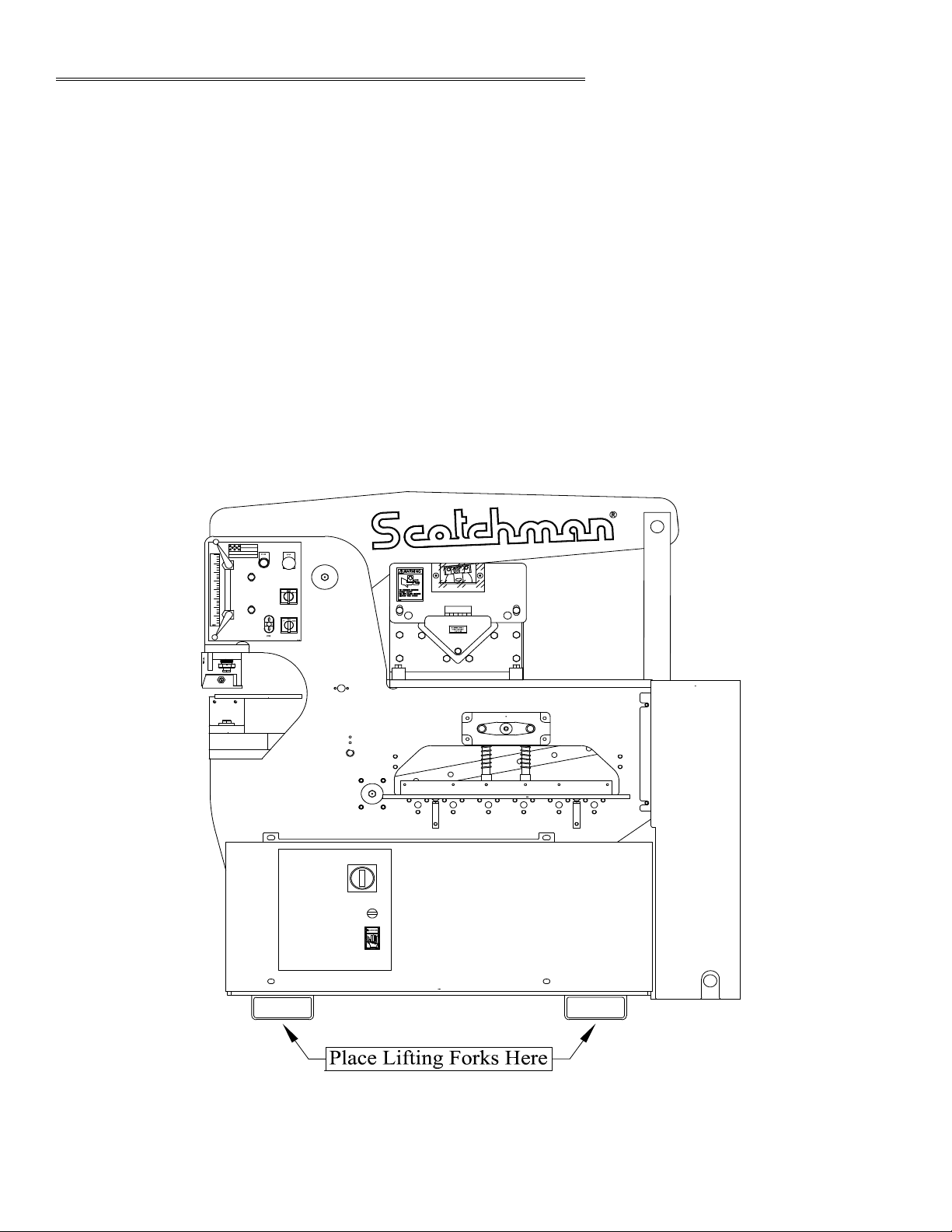
4.2 MACHINE MOVING PROCEDURES
This machine is designed to be moved with a forklift. The weight of this machine is 4,000 pounds
(1,818 Kg.). Check the capacity of the lifting equipment before attempting to move the machine.
THIS MACHINE IS TOP HEAVY AND SHOULD BE MOVED WITH CARE AND ON FLAT
SURFACES ONLY.
This is the quickest and safest means of moving the machine. The forks of the lift should be spread so
that they fit inside the lifting channels provided.
FIGURE 3

Page 13
After the machine has been located, remove the side shrouds and inspect the interior of the machine for
possible shipping damages.
CHECK SPECIFICALLY THE FOLLOWING ITEMS:
A. Stroke control handles and limit switches.
B. Pump and motor assembly.
C. Hydraulic hoses and fittings.
D. Starter box and control box.
E. Electrical connections.
F. Control valve.
The reservoir is full of oil. The recommended oil is a lightweight, non-foaming, anti-wear, hydraulic oil
such as Mobil DTE-25, with a minimum ISO cleanliness code of 20/18/15, or equivalent.
The reservoir holds 13.5 U.S. gallons (51 liters).
4.3 PHYSICAL INSPECTIONS
CAUTION: DO NOT OVER FILL!

Page 14
4.4 ELECTRICAL REQUIREMENTS
CAUTION: TO PREVENT DAMAGE TO THE MOTOR AND DANGER TO THE OPERATOR,
ALL ELECTRICAL CONNECTIONS SHOULD BE MADE BY A LICENSED ELECTRICIAN.
All machines are wired for three phase electrical power unless otherwise specified.
To insure satisfactory machine performance, the supply voltage should be (+ or -) 10% of the motor
voltage rating. Check the motor data tag for full load current requirements. The electrical diagram
for the machine is inside the cover of the control box. The diagrams are also ON THE FOLLOWING
THREE PAGES. For electrical supply lines ten feet (3m) or shorter, we recommend at least 12 gauge,
and preferably, 10. For longer electrical supply lines, use at least 10 gauge, and preferably, 8. We do not
recommend supply lines longer than twenty five feet (7.5m).
POWERREQUIREMENTS:
Motor frame 3PH = 182T 1PH = 184T
MOTOR VOLTAGE FULL LOAD CURRENT
(VAC) (AMPS)
208 15.5
230 14
460 7
575 5.9
230 (Single Phase) 23.5
Motor Power Rating: 5hp Speed 1,750 RPM
KVA Power Rating: 5.6 KVA Frequency 60 HZ
Starting Current: 210% Full Load
4.5 MACHINE START-UP
Before starting this machine, take time to thoroughly review the safety CD and the operator's manual.
This machine is equipped with a lock-out, disconnect switch. We strongly urge you to follow OSHA
directive CFR-1910.147 (effective 09-01-90) regarding lock-out, tag-out procedures. Before powering the
machine, be sure that all packing materials and tools have been removed from the machine and that the
work stations are clear. TO POWER THE MACHINE, place the disconnect switch in the ON position
and the selector switch in the START position. Power the machine by pushing the green START button.
Once the machine has been powered, it will not move until the selector switch has been placed in either
the PUNCH or the SHEAR position. Placing the selector switch in the PUNCH position will cause the
arms to move down. Placing the selector switch in the SHEAR position will cause the arms to move up. If
the machine does not move when the selector switch is placed in the PUNCH or SHEAR position, the
motor rotation is not correct and the electrician will have to switch two of the three supply line wires to
change the direction of rotation. Any time that the power to the machine has been turned off, the selector
switch must be placed in the START position to restart the machine.

Page 15
FIGURE 4A

Page 16
FIGURE 4B

Page 17
FIGURE 4C

Page 18
The stroke setting is important for the proper operation of the machine. If this setting has changed,
the machine may over-travel and cause the cylinder to "bottom out". This continued condition will
eventually cause the starter overload to open. It can also cause the hydraulic oil to overheat and damage
hydraulic system components. A slight change in the stroke setting can result in inadequate stroke to
operate the tooling.
A check of the machine’s stroke setting is made at the punch station; SEE FIGURE 5 ON THE
FOLLOWING PAGE. Set the stroke control handles (A) out to their farthest position. Turn the
selector switch (G) to the START position and power the machine. Then place this switch in the
SHEAR position. Measure the distance from the top of the punch bolster to the bottom of the punch
ram. The distance should be 9-1/32 inches (229mm). Turn the selector switch to the PUNCH position
and measure the distance. The distance should be 6-25/32 inches (172mm).
These dimensions are are + or - 1/16 of an inch (3mm).
IF THE STROKE IS OUT OF THESE LIMITS, THEN USE THE FOLLOWING PROCEDURE:
1. Loosen the two mounting plate screws (D) that hold the mounting plate to the machine.
SEE FIGURE 5 ON THE FOLLOWING PAGE.
2. Move the plate vertically, up or down. Moving the plate up will bring the distance down and a
movement down will bring the distance up.
3. Tighten the screws and re-check the dimensions. Repeat, if needed.
A. STROKE CONTROL HANDLES
B. SCALE - STROKE CONTROL
C. METERING BOSS
D. MOUNTING PLATE SCREWS
E. JOG CONTROL
F. JOG/RUN/PROBE SWITCH
G. PUNCH/START/SHEAR SWITCH
H. EMERGENCY STOP SWITCH
I. START BUTTON
4.6 MACHINE STROKE INSPECTION & ADJUSTMENT

Page 19
FIGURE 5
080061
080061
D
IH
EF
G
A
B
C
A
JOG
START STOP
RUN
JOG
START
SHEAR
PUNCH
PROBE
MM. IN.
MM. IN.
90
80
70
60
50
40
30
20
10
10
90
80
70
60
50
40
30
20
3
2
1
3
2
1
0
004085
DO NOT EXCEED
3 X 3 X 1/4
WHEN MITERING
0502003195
P/N 16247
65/90/120-AS
FI60/85-BK
90/120-RS
201110
M6x12
201110
M6x12
JOG
START STOP
RUN
JOG
START
SHEAR
PUNCH
PROBE
004085
7711 Sales - 7710 Assy.
080061
080061
9-1/32
(229mm)
UP
6-25/32
(172mm)
DOWN
Table of contents
Other Scotchman Lathe manuals


