Rotronic RMS-GW-915 User manual

www.rotronic.comEnglish
12.1067.9101E
RMS-GW-915
Short Instruction Manual
1 GENERAL DESCRIPTION
Congratulations on your new RMS gateway. The gateway transmits the
data of the wireless data loggers continuously to the RMS software by
Ethernet. These short instructions describe the main functions of the
device.
Please read this short manual and the instruction manual on
www.rotronic.com/rms carefully.
1.1 COMMISSIONING
The device must be supplied with 24 V (terminals: V+ / V-) or via PoE to be able to transmit data.
The gateway can be mounted easily with the wall bracket. The device is connected to the RMS
software by pairing.
Important: Port 80, DHCP
To integrate the device, port 80 must be enabled in your network and a DHCP server must assign
the IP address to the device.
2 INTEGRATION OF THE GATEWAY (PAIRING) IN 6 STEPS
1. If you do not want to connect the device to the Rotronic Cloud, the server must be congured
in the device.
a. Connect the device to the local network and start the RMS conguration software.
b. Search for the device under
Device > Search > Network Device
. The software nds all RMS
devices in the local network.
c. Enter the host (server address) and the
URL
of the software services under Settings.
d. Finish conguration with
Write
.
2. Log into the RMS software / cloud.
Select
Tools > Setup > Devices > New >
LAN device
3. Enter the serial number of the device.
4. Wait until the device is ashing orange.
Press the button on the device briey,
as shown in the picture on the RMS
software. The LED ashes green,
when connection is succesful.
5. Enter the device name, channel and
group.
6. Finish conguration.
3 LED INDICATORS
Status LED Function Meaning
Connected Flashes green Status OK
Flashes red 2 times: no connection to the server
Not connected Flashes orange Device in pairing mode, push the button for integ-
ration into the software
4 ACCESSORIES
AC1321 Mounting kit with Allen key and mounting cone
5 TECHNICAL DATA
Power supply: 24 VDC ±10 % / <100 mA
Power supply requirements: 24 VDC ±10 % / >4 W / limited power source
Range of measurement / application: -40…70 °C
IP protection: IP65
Software: RMS Monitoring Software
Weight: 200 g
6 DIMENSIONS
7 DELIVERY PACKAGE
• Gateway
• Wall bracket
• Short instruction manual
This equipment has been tested and found to comply with the limits for a Class A digital de-
vice, pursuant to part 15 of the FCC Rules. These limits are designed to provide reasonable
protection against harmful interference when the equipment is operated in a commercial
environment. This equipment generates, uses, and can radiate radio frequency energy
and, if not installed and used in accordance with the instruction manual, may cause
harmful interference to radio communications. Operation of this equipment in a residen-
tial area is likely to cause harmful interference in which case the user will be required to
correct the interference at his own expense
Any changes or modications to this device not explicitly approved by manufacturer could
void your authority to operate this equipment.
105 mm
113 mm
38 mm

Français www.rotronic.com
12.1067.9101F
RMS-GW-915
Mode d'emploi abrégé
1 DESCRIPTION GÉNÉRALE
Tous nos remerciements pour l’achat du gateway RMS. Cet appareil
transmet en continu, par Ethernet, les données du logger radio au lo-
giciel RMS. Ce mode d’emploi abrégé se limite à la description des fonc-
tions essentielles de cet appareil.
Veuillez lire avec attention ce manuel d’utilisation abrégé, ainsi que
le mode d’emploi que vous trouverez sur www.rotronic.com/rms.
1.1 MISE EN SERVICE
L’appareil doit être alimenté en courant 24V (barrette de raccordement : V+ / V-) ou par PoE, an que
les données puissent être transmises. Le gateway peut être xé facilement avec le support mural. La
liaison avec le logiciel RMS est effectuée par couplage.
Important: Port80, DHCP
An d’intégrer l’appareil, le port 80 doit être activé sur votre réseau et un serveur DHCP doit lui
attribuer une adresse IP.
2 INTÉGRATION DU GATEWAY (COUPLAGE) EN 6 ÉTAPES
1. Au cas où l’appareil ne doive pas être relié au Cloud Rotronic, le serveur doit être paramétré
sur l’appareil.
a. Relier l’appareil au réseau local et démarrer le logiciel RMS-Cong.
b.
Rechercher l’appareil avec Appareil > Rechercher > Appareil réseau.
Le logiciel trouve tous
les appareils RMS connectés au réseau local.
c. Entrer l’hôte (adresse du serveur) et l’URL du service logiciel dans Réglages.
d. Terminer la conguration avec Écrire.
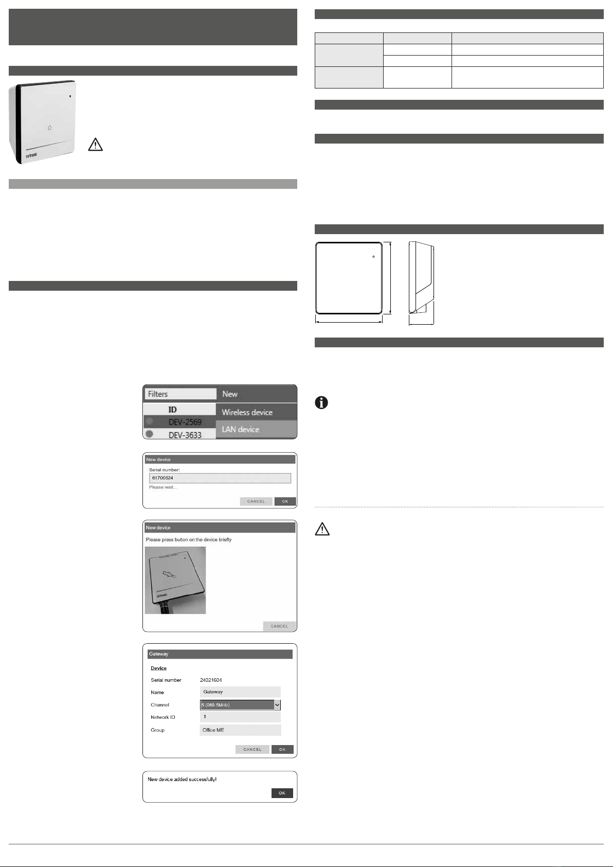
2. Effectuer la connexion avec le logiciel
RMS / Cloud. Choisir Extras
> Réglages >
Appareils > Nouveau > Appareil LAN
3. Entrer le numéro de série de l’appareil.
4. Attendre la n du clignotement orange
sur l’appareil. Appuyer brièvement le
bouton sur l’appareil, comme indiqué
sur l’image dans le logiciel RMS La LED
clignote en vert, lorsque la liaison a
été établie.
5. Entrer le nom de l’appareil, le canal
et le goupe
6. Terminer la conguration.
3 AFFICHAGE LED
Afchage de l’état Fonctions LED Signication
Relié Clignotement vert État OK
Clignotement rouge 2 fois: pas de liaison avec le serveur
Non raccordé Clignotement orange L’appareil est en mode de couplage, presser la
touche pour l’intégration au logiciel
4 ACCESSOIRES
AC1321 Kit de montage avec clé à 6 pans et cône de montage
5 CARACTÉRISTIQUES TECHNIQUES
Tension d’alimentation 24 VCC ±10 % / < 100 mA
Exigences de l’adaptateur secteur : 24 VCC ±10 % / > 4 W / Source de courant à puissance limitée
Gammes de mesure et d’utilisation -40…70 °C
Protection IP IP65
Logiciel Logiciel RMS de monitoring
Poids 200 g
6 DIMENSIONS
7 FOURNITURES
• Gateway
• Support mural
• Mode d'emploi abrégé
Cet instrument a été testé et respecte les valeurs limites pour un appareil numérique de la
classe A, selon la partie 15 des règles FCC. Ces règles sont destinées à offrir une protection
adéquate, lorsque l’appareil est utilisé dans un environnement commercial. Cet appareil
produit, utilise et émet des rayonnements à haute fréquence et peut avoir une inuence
négative sur le trafc radio sil n’est pas installé et utilisé selon les instructions fournies.
L’utilisation dans une zone d’habitat provoquera probablement des interférences nocives,
l’utilisateur doit dans ce cas entreprendre les contre-mesures nécessaires, à ses frais, pour
éliminer ces interférences.
Des modications et autres interventions, non formellement autorisées par le fabricant,
peuvent entraîner la non conformité de l'autorisation de service pour cet appareil.
105 mm
113 mm
38 mm

Deutsch www.rotronic.com
12.1067.9101D
RMS-GATEWAY
Kurzbedienungsanleitung
1 ALLGEMEINE BESCHREIBUNG
Herzlichen Glückwunsch zum Kauf des RMS-Gateways. Das Gateway
übermittelt die Daten der Funkdatenlogger kontinuierlich per Ethernet
an die RMS-Software. Diese Kurzbedienungsanleitung beschreibt die
wichtigsten Funktionen des Geräts.
Bitte lesen Sie diese Kurzbedienungsanleitung sowie die Bedie-
nungsanleitung unter www.rotronic.com/rms genau durch.
1.1 INBETRIEBNAHME
Das Gerät muss mit 24 V (Klemmleiste: V+ / V-) oder PoE versorgt werden, damit die Daten übertra-
gen werden können. Das Gateway lässt sich einfach mit der Wandhalterung befestigen. Die Verbin-
dung mit der RMS-Software wird per Pairing hergestellt.
Wichtig: Port 80, DHCP
Für die Einbindung des Geräts muss der Port 80 in ihrem Netzwerk freigeschaltet sein, und ein
DHCP-Server muss die IP-Adresse an das Gerät zuweisen.
2 EINBINDUNG DES GATEWAYS (PAIRING) IN 6 SCHRITTEN
1. Falls das Gerät nicht mit der Rotronic Cloud verbunden werden soll, muss der Server im Gerät
eingestellt werden.
a. Gerät mit dem lokalen Netzwerk verbinden und RMS-Kong-Software starten.
b.
Gerät unter Gerät > Suchen > Netzwerkgerät suchen.
Die Software ndet alle RMS-Geräte
im lokalen Netzwerk.
c. Unter Einstellungen den Host (Adresse des Servers) und die URL des Software-Services
angeben.
d. Konguration mit Schreiben abschliessen.
2. In die RMS-Software / Cloud einloggen.
Extras
> Setup > Geräte > Neu >
LAN-Gerät wählen
3. Seriennummer des Geräts eingeben.
4. Warten, bis das Gerät nicht mehr orange
blinkt. Knopf am Gerät kurz drücken,
wie in der Abbildung in der RMS-Soft-
ware dargestellt. Die LED blinkt grün,
wenn die Verbindung hergestellt wurde.
5. Gerätenamen, Kanal und Gruppe
eingeben.
6. Konguration abschliessen.
3 LED-ANZEIGEN
Statusanzeige LED-Funktion Bedeutung
Verbunden Blinkt grün Status OK
Blinkt rot 2-mal: keine Verbindung zum Server
Nicht verbunden Blinkt orange Gerät im Pairing-Modus, Taste zur Einbindung in
der Software drücken
4 ZUBEHÖR
AC1321 Montage-Kit mit Inbusschlüssel und Montagekonus
5 TECHNISCHE DATEN
Spannungsversorgung: 24 VDC ±10 % / < 100 mA
Netzteil-Anforderungen: 24 VDC ±10 % / > 4 W / Stromquelle mit begrenzter Leistung
Mess- und Einsatzbereich: -40…70 °C
IP-Schutz: IP65
Software: RMS Monitoring-Software
Gewicht: 200 g
6 ABMESSUNGEN
7 LIEFERUMFANG
• Gateway
• Wandhalterung
• Kurzbedienungsanleitung
Dieses Gerät wurde getestet und entspricht den Grenzwerten für ein digitales Gerät der
Klasse A entsprechend Teil 15 der FCC-Regeln. Diese Regeln sind dazu bestimmt, einen
angemessenen Schutz gegen Störungen zu bieten, wenn das Gerät in einer kommerziell
genutzten Umgebung betrieben wird. Dieses Gerät erzeugt, nutzt und emittiert Hochfre-
quenzstrahlung und kann sich bei einer nicht den Anweisungen entsprechenden Installa-
tion und Verwendung negativ auf den Funkverkehr auswirken. Bei Betrieb dieses Geräts in
einem Wohngebiet wird wahrscheinlich schädliche Interferenz erzeugt, in welchem Fall der
Benutzer die erforderlichen Gegenmassnahmen treffen muss, um die Interferenz auf eigene
Kosten zu beheben
Änderungen oder sonstige vom Hersteller nicht ausdrücklich genehmigte Eingriffe in das
Gerät können Ihre Betriebszulassung für dieses Gerät hinfällig machen.
105 mm
113 mm
38 mm
Table of contents
Languages:
Other Rotronic Gateway manuals
Popular Gateway manuals by other brands

Moxa Technologies
Moxa Technologies MGate 5102-PBM-PN user manual

Beijer Electronics
Beijer Electronics korenix JetWave 3220v3 Series user manual

Multitech
Multitech MULTIVOIP MVP-210 user guide

PhoneGnome
PhoneGnome PhoneGnome Box user guide

OpenVox
OpenVox DGW-100XR user manual

Cisco
Cisco ASR 5000 Series Administration guide