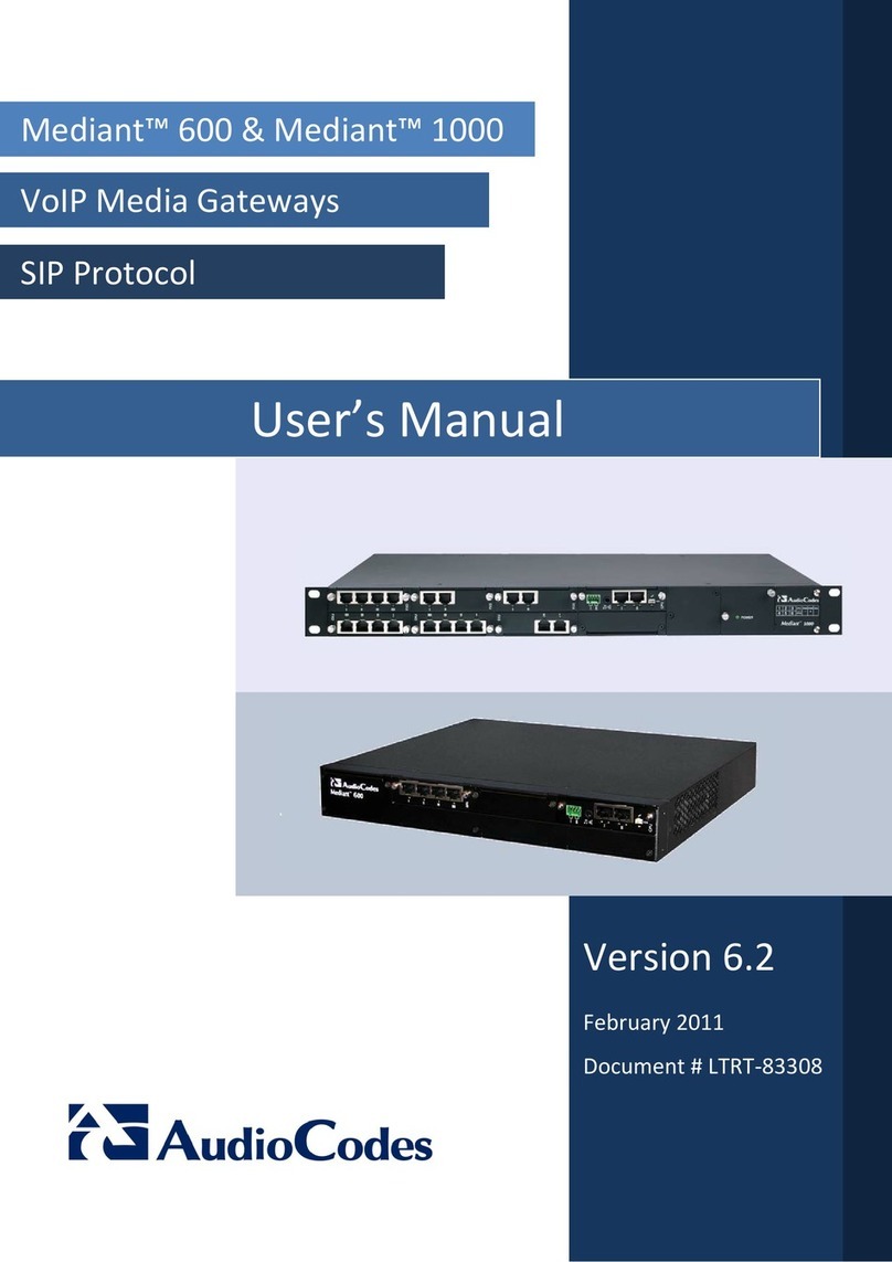
Version 6.2 5 February 2011
Installation Manual Contents
List of Figures
Figure 1-1: Summary of Installation Steps............................................................................................... 9
Figure 2-1: Front Panel.......................................................................................................................... 11
Figure 2-2: Rear Panel .......................................................................................................................... 13
Figure 2-3: Rubber Foot Attached to Underside of Device.................................................................... 15
Figure 2-4: Peeled-off Rubber Foot ....................................................................................................... 15
Figure 2-5: Mounting Bracket (Right)..................................................................................................... 17
Figure 2-6: Attaching the Mounting Brackets ........................................................................................ 17
Figure 2-7: Earthing the Device ............................................................................................................. 19
Figure 2-8: Connecting the WAN Port ................................................................................................... 20
Figure 2-9: Connecting the T1 WAN DSU/CSU Port............................................................................. 21
Figure 2-10: RJ-48c T1 WAN Connector Pinouts.................................................................................. 21
Figure 2-11: Connecting the SHDSL WAN Port .................................................................................... 22
Figure 2-12: Connecting the LAN Ports................................................................................................. 23
Figure 2-13: Connecting FXS and FXO Ports (Example Hardware Configuration 4 FXS/4 FXO)........ 25
Figure 2-14: RJ-11 Connector Pinouts .................................................................................................. 25
Figure 2-15: Cabling FXS Lifeline.......................................................................................................... 26
Figure 2-16: RJ-11 Connector Pinouts for FXS Lifeline ........................................................................ 26
Figure 2-17: RJ-45 Connector Pinouts for BRI Ports ............................................................................ 27
Figure 2-18: Cabling BRI Ports.............................................................................................................. 27
Figure 2-19: RJ-48c Connector Pinouts for E1/T1 ................................................................................ 28
Figure 2-20: Cabling OSN Server Ports ................................................................................................ 29
Figure 2-21: RS-232 Cable Adapter ...................................................................................................... 31
Figure 2-22: Cabling the Power ............................................................................................................. 32
Figure 2-23: Replacing the Power Fuse ................................................................................................ 33
Figure 2-24: Extracted Power Fuse ....................................................................................................... 34
Figure 3-1: Login Screen ....................................................................................................................... 36
Figure 3-2: Steps for Configuring VoIP and Data-Routing Functionalities ............................................ 37
Figure 3-3: Multiple Interface Table Page ............................................................................................. 38
Figure 3-4: Connections Page ............................................................................................................... 39
Figure 3-5: Defining LAN Data-Routing IP Address .............................................................................. 39
Figure 3-6: Configuring the DHCP Server ............................................................................................. 40
Figure 3-7: Configuring the WAN IP Address........................................................................................ 41
Figure 3-8: Routing Tab......................................................................................................................... 41
Figure 3-9: Selecting WAN Interface for VoIP Traffic in Multiple Interface Table Page ........................ 42
Figure 3-10: Assigning WAN Interface to SIP Interface ........................................................................ 42
Figure 3-11: Assigning WAN Interface to Media Realm ........................................................................ 43
Figure 3-12: Traffic Shaping Page......................................................................................................... 44
Figure 3-13: Selecting Device for Traffic Shaping ................................................................................. 44
Figure 3-14: Defining Traffic Shaping .................................................................................................... 45
Figure 3-15: Adding Shaping Class Name (for VoIP Tx Traffic)............................................................ 45
Figure 3-16: Defining Shaping Class (for VoIP Tx Traffic) .................................................................... 46
Figure 3-17: Configured Traffic Shaping for Total WAN and VoIP Bandwidth...................................... 46
Figure 3-18: Match Rules Page ............................................................................................................. 47
Figure 3-19: QoS Output Traffic Matching Rules .................................................................................. 48
Figure 3-20: Defining Incoming SIP Ports ............................................................................................. 48
Figure 3-21: Defining SIP Ports (e.g. TCP) ........................................................................................... 49
Figure 3-22: Traffic Matching Rule for Received SIP Signaling Traffic ................................................. 49
Figure 3-23: Matching Rule for Received RTP Traffic........................................................................... 50
Figure 3-24: Traffic Matching Rule for WAN Tx/Rx RTP and SIP Signaling ......................................... 50
Figure 3-25: Defining WAN HTTP Port.................................................................................................. 51
Figure 3-26: Removing Data-Routing Connection Interface ................................................................. 51
Figure 3-27: Multiple Interface Table for Network without VLANs......................................................... 52
Figure 3-28: Multiple Interfaces with VLANs ......................................................................................... 52
Figure 3-29: Defining VLANs per LAN Port ........................................................................................... 52
Figure 3-30: Maintenance Actions Page ............................................................................................... 53
Figure 3-31: WEB User Accounts Page (for Users with 'Security Administrator' Privileges) ................ 54


