www.rovingnetworks.com Version 1.01 9/28/2012 2
OVERVIEW
This document describes the hardware and software setup for Roving Networks RN-XV-RD2 evaluation board, which
allows you to evaluate the RN-XV 802.11 b/g module. The RN-XV module, which is sold separately, mounts to the
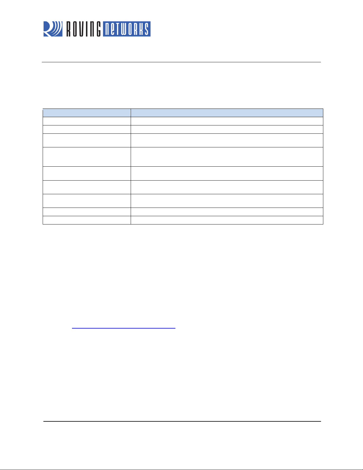
evaluation board and contains the RN-171 Wi-Fi module. Table 1 describes the board’s components.
Connector socket for the RN-XV The RN-XV module’s pins slide into the socket.
Three status LEDs These LEDs mimic the LEDs on the RN-XV.
Four pushbutton switches These switches are hard-wired to the RN-XV module and provide reset, ad hoc/WPS
mode, access to sensor 2, and access to GPSW (GPIO14).
Two 10-amp, 250-V relays The board has two relays with connectors (J7 and J6) that you can connect to a variety
of electronics or appliances. After you have programmed the module, you can operate
the connected electronics remotely over Wi-Fi.
Built-in temperature sensor The board includes a temperature sensor (SEN5) that allows the module to wake or
sleep depending on the ambient temperature.
External temperature probe connector You can attach an external temperature probe to the board using the connector at
SEN3.
USB cable A USB cable connected to the board allows you to connect directly from the board to
your computer, e.g., for programming the module over the UART.
10 GPIO pins The board contains access to 10 GPIO pins via the 3.3-V headers at J3 and J5.
Voltage regulator The voltage regulator controls the voltage levels on the board.
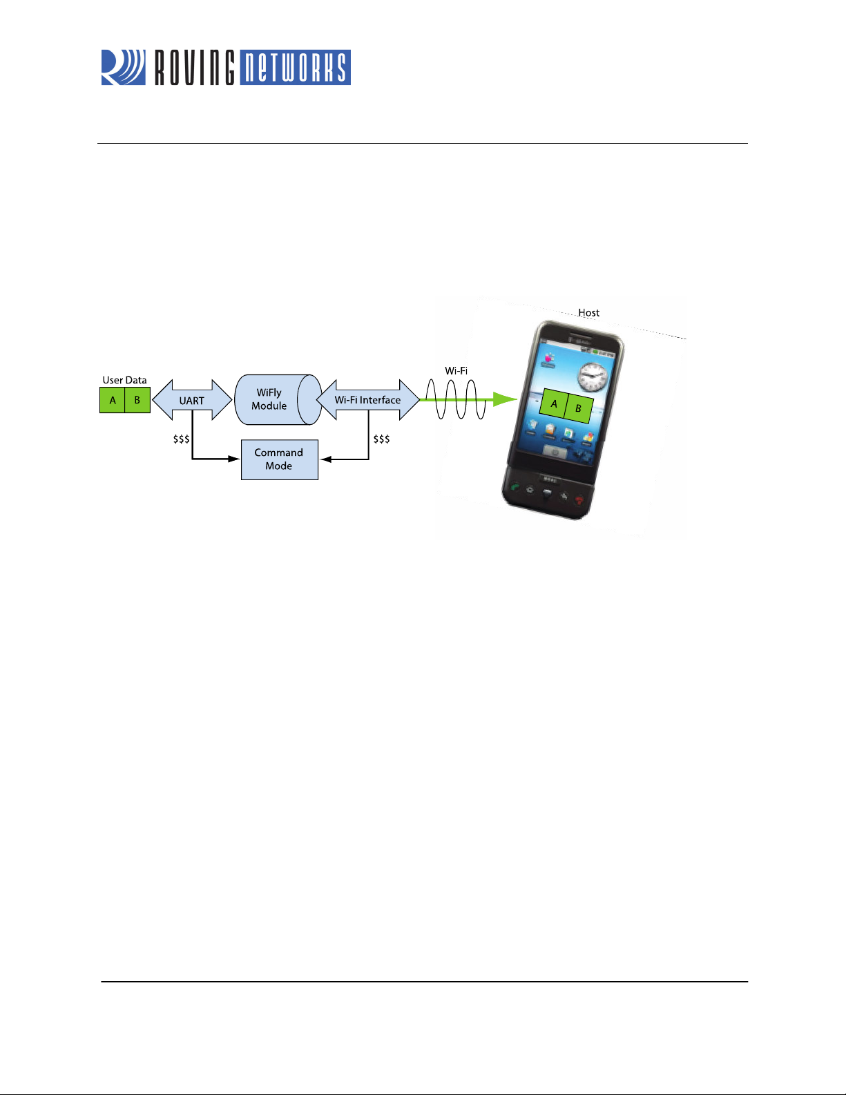
You can configure and program the WiFly module using the command interface, create connections, and transfer
data. The command interface is made up of simple ASCII commands. See “Resources & Related Documents” on
page 15 for information on available documentation.
Evaluation Board Description
The RN-XV-RD2 evaluation board connects to your computer using a USB cable. To evaluate the RN-XV module on
the evaluation board, you need a computer with a USB port running either the Microsoft Windows or Mac OS-X
operating system.
NOTE: Before beginning your evaluation, you must install the FTDI drivers for the USB cable. You can download
the drivers (as well as other tools and utilities) from the Roving Networks website at
http://www.rovingnetworks.com/support.php.
Figure 1 shows the RN-XV-RD2 evaluation board and pin information. Table 2 describes the LED indicators.