KIT VENTILAZIONE cod. 004722623 - 04/2011 9/12
ESFD
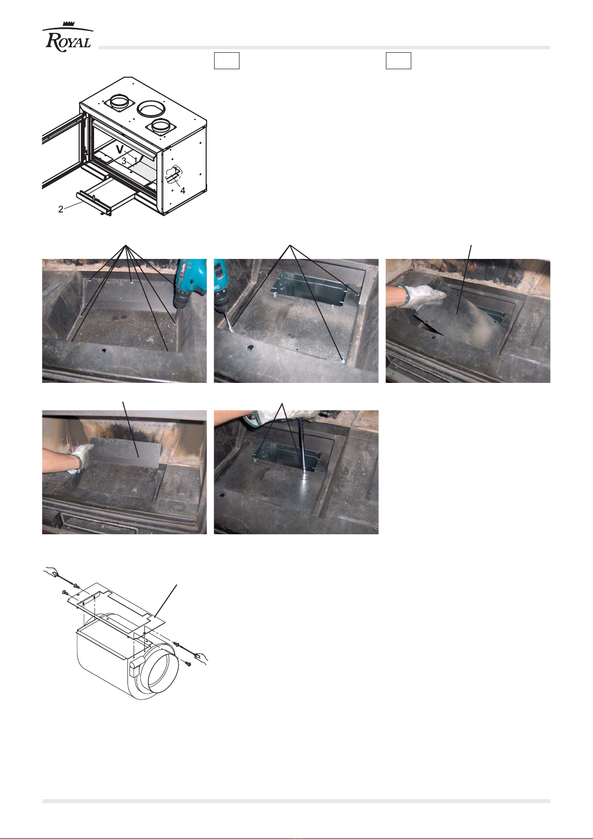
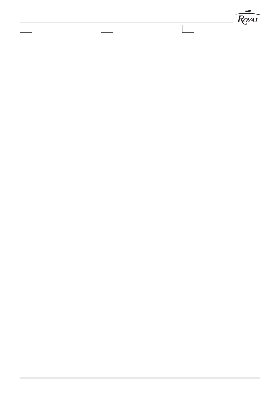
1.7 POSE TAMPONS ANTÉRIEURS
(FIG. 9)
Oter les bouchons (6) situés sur la façade
sous la base en fonte.
Poser les deux tampons de fermeture
frontale (7) en les vissant à partir de la
partie antérieure du poêle.
Replacer et revisser les bouchons (6).
Avec le kit de ventilation en option revisser
les bouchons (6) après avoir monté le
thermostat.
DANGER
Vérifiez qu'il n'y ait pas de tension dans
le raccordement à l’Inserto avant chaque
opération.
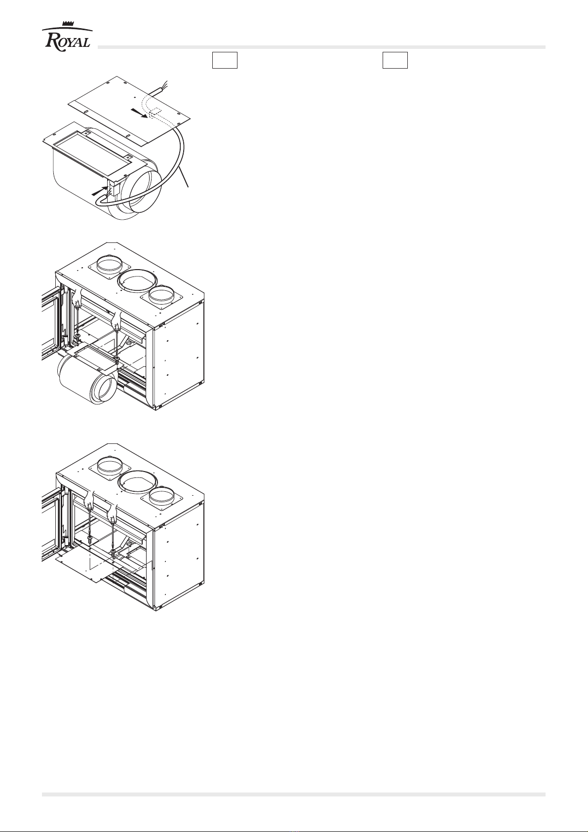
1.8 RACCORDEMENTS
ÉLECTRIQUES
1.8.1 Installation de la ventilation
frontale
Visser le thermostat (8) sur la structure
du foyer en bas à gauche.
Raccorder le câble à deux fils au
thermostat (8) avec les fastons.
Raccorder le câble d'alimentation (E) au
ventilateur.
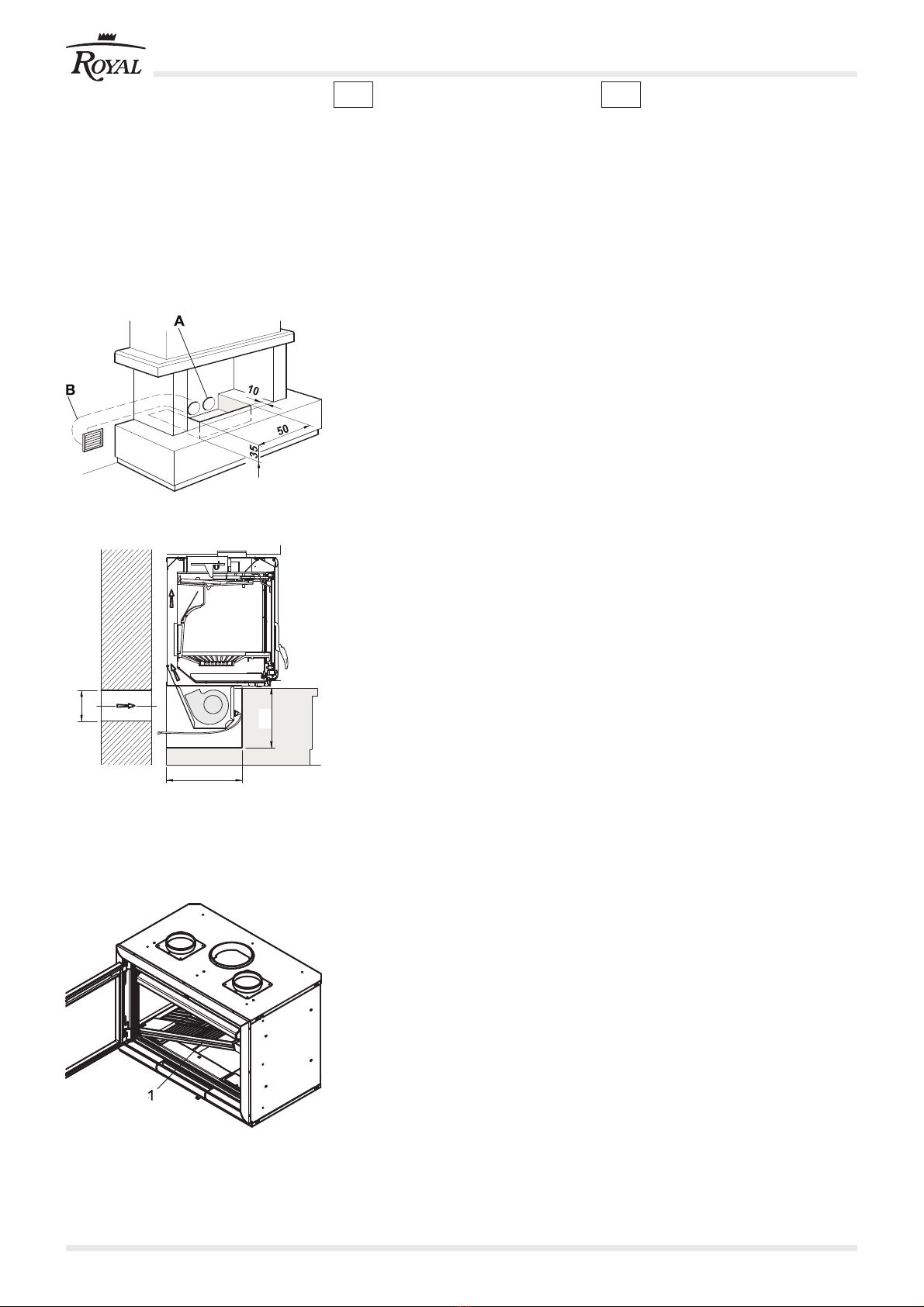
La centrale (9) doit être installée loin des
sources de chaleur et selon les modalités
présentées dans la page d'instructions.
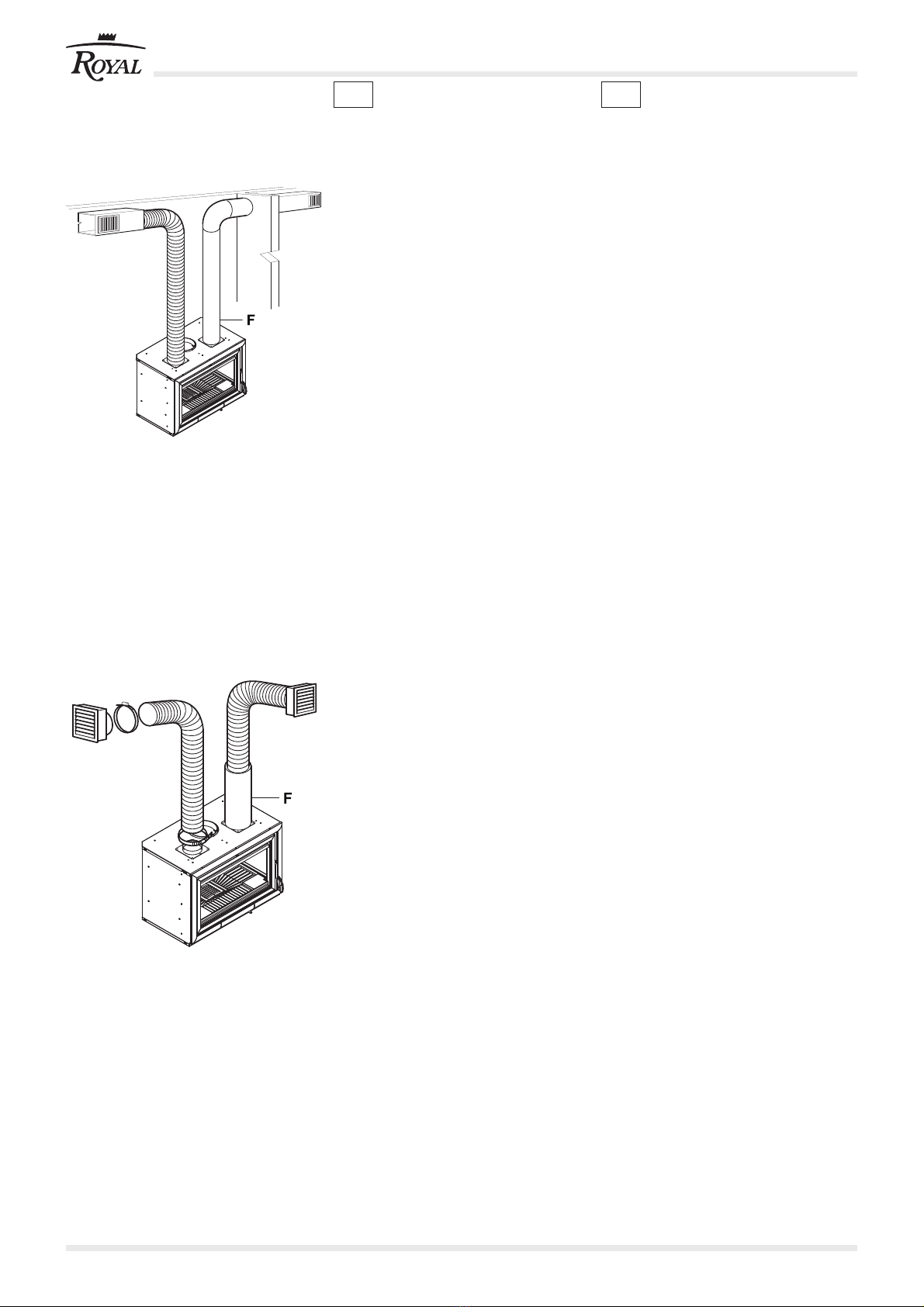
1.8.2 Installation du Kit
Ventilation en option + Kit
hotte
Monter la sonde (12) dans le conduit d'air
au moyen du serre-sonde prévu à cet effet
Raccorder la sonde (12) au tableau
électrique (10) avec le câble (11).
Raccorder le câble d'alimentation (E) au
fan.
La tableau électrique (10) doit être installé
loin des sources de chaleur et selon les
modalités présentées dans la page
d'instructions.
1.7 EINSETZEN DER VORDEREN
PUFFER (FIG. 9)
Die Kappen (6) auf der Vorderseite unter
dem Unterteil aus Gusseiseb,
abnehmen.
Die zwei vorderen Abschlusspuffer (7)
einsetzenund am vorderen Teil des
Heizofens festschrauben.
Die Kappen (6) wieder einsetzen und
anschrauben.
Beim zusätzlichen Ventilationsbausatz, die
Kappen (6)nach der Montage des
Thermostats wieder anschrauben.
GEFAHR
Vor jedem Eingriff sicherstellen, dass in
den Stromleitungen zum Inserto keine
Spannung vorhanden ist.
1.8 STROMANSCHLÜSSE
1.8.1 Installation zusätzlicher
Ventilationsbausatz
Das Thermostat (8) unten links am
Korpus des Feuerraums anschrauben.
Das 2-drähtige Kabel mittels
Fastonstecker am Thermostat (8)
anschließen.
Das Stromkabel (E) am Lüfter
anschliessen.
Die Steuereinheit (9) muss von den
Wärmequellen entfernt installiert werden
und zwar entsprechend den Anweisungen
des Beiblattes.
1.8.2 Installation zusätzlicher
Ventilationsbausatz +
Bausatz Abzugshaube
Den Fühler (12) in der Luftrohrleitung mit
der entsprechenden Fühlerhalterung
installieren.
Den Fühler (12) an der Steuereinheit(10)
mit dem Kabel (11) anschliessen.
Das Stromkabel (E) am Lüfter
anschliessen.
Die Steuereinheit (10) muss von den
Wärmequellen entfernt installiert werden
und zwar entsprechend den Anweisungen
des Beiblattes.
1.7 INCORPORACIÓN DE LOS
TAMPONES ANTERIORES (FIG.
9)
Quitar los tapones (6) ubicados en el
frontal, bajo la base de hierro fundido.
Introducir los dos tampones del cierre
frontal (7), enroscándolos desde la parte
delantera de la estufa.
Volver a colocar y a enroscar los tapones
(6).
En el caso de Kit de ventilación opcional,
volver a enroscar los tapones (6) tras
haber montado el termostato.
PELIGRO
Comprobar que no hay tensión en la
conexión con el INSERTO antes de
cualquier operación.
1.8 CONEXIONES ELÉCTRICAS
1.8.1 Instalación del Kit de
ventilación opcional
Enroscar el termostato (8) en la estructura
del hogar, en la parte inferior izquierda.
Conectar el cable de 2 hilos al termostato
(8) mediante los faston.
Conectar el cable de alimentación (E) al
abanico.
La centralita (9) debe instalarse alejada
de las fuentes de calor, según las
modalidades descritas en la hoja
correspondiente.
1.8.2 Instalación del Kit de
ventilación opcional + Kit
campana
Instalar la sonda (12) en el tubo de
canalización de aire usando el retén para
sonda adecuado.
Conectar la sonda (12) a la centralita (E)
con el cable (11).
Conectar el cable de alimentación (C) al
abanico.
La centralita (10) debe instalarse alejada
de las fuentes de calor, según las
modalidades descritas en la hoja
correspondiente.