CFM TF140-EC Maintenance and service guide

READ AND SAVE THESE INSTRUCTIONS FOR FUTURE REFERENCE.

NOTICE
SAFETY INSTRUCTIONS
2
TF140-EC fan is not explosion proof and should not be used when a potentially
explosive situation exists.
To reduce the risk of re, electric shock, or injury to persons—observe the following:
1. Use this unit only in the manner intended by the manufacturer. If you have questions, contact
the factory.
2. Before installing or servicing, switch power o at service panel and lock the service
disconnecting means to prevent power from being switched on accidentally. Do not re-
establish power supply until fan and activation device are completely installed. When the
service disconnecting means cannot be locked, securely fasten a prominent warning device,
such as a tag, to the service panel.
3. A qualied person(s) must perform installation work and electrical wiring in accordance with
all applicable codes and standards, including re-rated construction.
4. Sucient air is needed for proper combustion and exhausting of gases through the ue
(chimney) of fuel burning equipment to prevent backdrafting. Follow the heating equipment
manufacturer’s guidelines and safety standards as published by the National Fire Protection
Association (NFPA), the American Society of Heating, Refrigeration, and Air Conditioning
Engineers (ASHRAE), and local code authorities.
5. When cutting or drilling into walls or ceilings, take care not to damage electrical wires or
other hidden utilities.
6. Ducted fans must always be vented to the outdoors.
7. TF140-EC fan is suitable for installation over a shower or tub when connected to a GFCI
(Ground Fault Circuit Interrupter) protected branch circuit.
8. This unit must be grounded.
9. Do NOT use this fan with any solid-state speed control device.
10. The fan must not be installed in a ceiling that is thermally insulated to a value greater than R40.
1. For general ventilation use only. Do not use to exhaust hazardous or explosive materials and vapors.
2. TF140-EC fan is designed for installation in ceilings up to a 12/12 pitch (45 degree angle).
Duct connector must point up. DO NOT MOUNT THIS PRODUCT IN A WALL.
3. To avoid motor bearing damage and noisy and/or unbalanced impellers, keep drywall spray,
construction dust, etc. o power unit.
4. Check voltage at the fan to see that it corresponds to the motor nameplate.
5. TF140-EC fan is not suitable for use in kitchens or cooking areas.

WARNING
CAUTION

3
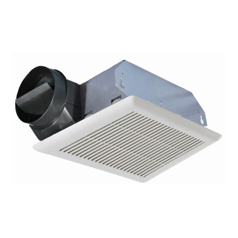
TF140-EC TRANQUIL BATHROOM FANS
MODEL: TF140-EC
Thedeliverysetincludes: • Housing • Mountinghardware
• Ductassembly • Blowerassembly
• Grille • Powerboxknobs
TWO WAYS TO CONNECT DUCTWORK TO A UNIT
Ducting has a strong eect on the airow, noise and energy use of the fan. Use the shortest, straightest duct routing possible
for best performance, and avoid installing the fan with smaller ducts than recommended. Insulation around the ducts can
reduce energy loss and inhibit mold growth. Fans installed with existing ducts may not achieve their rated airow.
Insulation* (place around and over fan housing)
Power cable*
Seal gaps around housing
Round duct*
Seal duct joints with tape*
Roof cap*
(w/built-in damper)
*NOT INCLUDED WITH FAN
Round elbows*
Fan Housing
Wall cap*
(w/built-in damper)
Keep duct runs short
11.375”
10.5”
7.625"
14"
13"

4
FAN INSTALLATION
Disconnect and lock out power supply before performing any installation
work. Working on or near energized equipment could result in death or serious injury.
STEP 1. INSTALL HOUSING
Hanger bars span up to 24 inches and can be
used on all types of framing. Slide hanger bars
onto the housing and adjust to t between
framing (Figure 1). Position the tabs of the
hanger bars ush with bottom of framing.
Secure the hanger bars to framing using one
screw on each end of hanger bar. Next select a
proper hole and secure hanger bars together
with one screw (Figure 2).
STEP 2. INSTALL DUCT
Using the recommended duct size, connect
round ductwork (not included) to the
damper/duct connector (Figure 3), and run
duct to an exterior roof or wall cap using the
shortest, straightest duct routing possible for
best performance. Secure all the ductwork
connections with tape (not included),
ensuring all duct connections are airtight.
Note: Ducting has a strong eect on the
airow, noise and energy use of the fan.
Use the shortest, straightest duct routing
possible for best performance, and avoid
installing the fan with smaller ductwork than
recommended. Fans installed with existing
ductwork may not achieve their rated airow.
Insulation around the ductwork can reduce
energy loss and inhibit mold growth.
STEP 3. CONNECT WIRING
R
efer to wiring diagrams on page 5. Reattach
all electrical box covers before applying power.
STEP 4. INSTALL GRILLE
Insert sensor plug into the plug base on the
power box before installing the grille. Pinch
the springs on the sides of grille and insert
them into the slots in the housing. Firmly push
the grille against the ceiling to secure (Figure 4).
Before applying power, ensure all electrical box
covers are installed.
WARNING
NOTICE
screw
Hanger
Bar
Figure 4
Figure 3
Figure 2
Figure 1

5
WIRING DIAGRAM
Run 120V AC house wiring to the location of the fan. Use only UL-approved connectors (not
included) to attach the house wiring to the wiring plate.
MODEL: TF140-EC
SWITCH I
SWITCH II
JUNCTION BOX
FAN
UNIT
WHITE
BLACK
BROWN
GROUND
BLACK
WHITE
GROUND
LINE
IN
Note: Switch I and switch II are supplied by others.

The Power Box, located inside the fan housing, has four separate adjustments:
a. Toggle Switch positions determine the maximum
airow rate (factory set to 110 cfm). To select the
desired airow (80, 110 or 140 cfm), set toggle
switch 1 & 2 according to one of three switch
positions in the table.
b. Low Airow Knob “S” adjusts the low airow
rate from 30 cfm up to the maximum airow
rate set with the toggle switch. The low airow
is deactivated (fan stops after pre-set time delay)
when set between OFF and 30 cfm.
c. Humidity Sensor Knob “H” is adjustable from
OFF to 80%. The humidity sensor is deactivated
when set between OFF and 30%.
d. Time Delay Knob “T” is adjustable from 5 to 60
minutes. The time delay will switch the fan to the
low speed setting after Switch II is turned OFF
for the set period of time. The time delay is de-
activated when set between OFF and 5 minutes.
The above knobs have been factory set to OFF. To adjust a knob’s settings, observe the follow:
a. Disconnect power at service entrance.
b. Remove the grille and locate the slot marked “S” (Low Airow), “H” (Humidity Sensor) or “T”
(Time Delay) on the control box inside the fan.
c. Carefully rotate the knob adjustment toward the preferred setting.
d. Turn on power.
After an adjustment to the slot marked “H” (Humidity Sensor), check operation by running a
shower or other humidity source until the fan turns on. Repeat above steps if necessary. Humidity
sensor response may deviate depending on air temperature change.
6
FAN CONTROLS
Toggle Switch
Position
Airow (CFM)
80
12
110
12
140
12
To change the pre-selected airow, adjust
toggle switch positions as per the table above.
is the position of switch.
H
30%
45% 60%
80%
OFF
Humidity
Sensor
Knob
T
OFF 60min
20min 40min
5min
Time
Delay
Knob
S
Max.
30
CFM
60% 80%
OFF
Low
Airow
Knob

7
FAN OPERATION
When the fan is OFF, by turning ON both Switch I and Switch II, the fan will start and run at the
maximum airow rate pre-set by the Toggle Switch. This function is independent of the pre-set
Low Airow, Time Delay, and Humidity Sensor.
If turning OFF Switch II, the fan will continue to run for the number of minutes pre-set on the Time
Delay Knob and then it will automatically switch to the low airow rate or OFF.
With only Switch I ON, the fan will automatically start if any of the following conditions are met:
• If the Low Airow Knob position is anywhere above 30 cfm, the fan will run continuously
at the pre-set low airow rate.
• If the Humidity Sensor detects a relative humidity above the pre-set value or a rapid
increase in humidity, the fan will run at the maximum pre-set airow rate. When the pre-set
humidity level is reached, the fan will continue to run for the selected number of minutes
set on the Time Delay Knob. After that, the fan will switch to the pre-set low airow rate (if
set above 30 cfm) or stop (if set OFF or below 30 cfm).
• If the optional motion sensor is installed and detecting motion, the fan will run at the maximum
pre-set airow rate
until
after the last detection of motion and the pre-set time delay has
elapsed. After that, the fan will switch to the pre-set low airow rate (if above 30 cfm) or stop (if
OFF or below 30 cfm).
Turning OFF Switch I will stop the fan from any of the operating situations above.
If the optional motion sensor grille is installed and motion is detected, the fan shifts automatically
to the maximum pre-set airow rate. After the last detection of motion, the fan will continue to
operate at the maximum pre-set speed until the user-set time delay has passed. At the end of the
time delay, the fan speed will return to its previous state.
5 to 7 feet
Gesture Area
Sensor 90°
MOTION SENSOR OPERATION

Bualo, New York | Mississauga, Ontario | Dayton, Ohio
www.continentalfan.com | 1-800-779-4021
TF140-EC-I&M-2304
ACCEPTANCE CERTIFICATE
CONNECTION CERTIFICATE
The TF140-EC fan has been duly certied as serviceable.
Manufactured on (date): Date of sale:
Sold by:
(name of trading enterprise, stamp of store)
Company name:
Electrician name:
Date: Signature:
Due to constant product improvements, some models may dier slightly from those portrayed in this manual.
TROUBLESHOOTING
Only qualied personnel should work on electrical equipment. Working on or
near energized equipment could result in death or serious injury.
1. If the fan fails to start, consult wiring diagram to ensure proper connection.
2. Check the incoming supply for proper voltage.
3. Ensure that the electrical service to the fan is locked in the“OFF”position.
4. Use a meter to test for continuity across the fan motor leads.
5. If the motor leads show continuity, rewire the fan.
6. Turn on the electrical supply and restart.
7. If the fan fails to start, please contact factory.
WARNING
RECOMMENDED MAINTENANCE
Disconnect and lock out power supply before performing any maintenance.
Working on or near energized equipment could result in death or serious injury.
1. The motor is permanently lubricated. No additional lubrication is necessary.
2. Periodic inspection, based upon usage, should be performed to ensure that the fan impeller
is not obstructed.
3. Excessive fan noise or vibration may indicate an obstructed impeller.
4. To inspect and clean impeller:
a. Remove the grille from the fan and remove any obstruction from the impeller.
b. Vacuum the interior of the unit.
c. Reconnect the grille to the fan.
d. Turn power supply on.
WARNING
Table of contents
Other CFM Fan manuals

CFM
CFM WEB-0807 User manual

CFM
CFM TF140-DC Maintenance and service guide

CFM
CFM AeroFan User manual

CFM
CFM AIB-1006 User manual

CFM
CFM TF400 Maintenance and service guide

CFM
CFM SEF Installation and operating instructions

CFM
CFM APK-0906 User manual

CFM
CFM HRV-0904 User manual

CFM
CFM 167219 User manual

CFM
CFM 167193 User manual

CFM
CFM MNC-250 User manual

CFM
CFM AXC100B User manual

CFM
CFM CF Maintenance and service guide

CFM
CFM APW-0906 User manual

CFM
CFM TBF90 Installation and operating instructions

CFM
CFM TF Series Maintenance and service guide

CFM
CFM TNC-0506 User manual

CFM
CFM 165596 User manual

CFM
CFM 165834 User manual

CFM
CFM FCU-08 User manual