RSF Woodburning Fireplaces FO-FDHB5-N User manual

FO-FDHB5-N-2007-08
FO-FDHB5-N
Internal Blower for Delta, Onyx, Opel
The internal blower kit will increase the circulation of heated air generated by the fireplace into the room
where it is installed. If you desire to distribute the heat in different rooms, please refer to central heating
and zone heating kits (FO-FDHB6-1, FO-FDHC6, FO-FDHCZ1 and FO-FDHCZ2).
All wiring should be in accordance with local ordinances and the National Electric Code.
One thermal switch is all that is required to operate the internal blower, the central heating blower or
both. If the thermal switch is already installed, skip to the installation of the internal blower.
INSTALLATION ON A DELTA
Installation of the thermal switch assembly
1. Remove the bottom central and right louvers.
2. The thermal switch goes in the middle of the central bottom louver opening, on the flange at the
back of the shield below the firebox, with the thermal switch facing upwards (see Figure 1). Make
sure to push the “S” clips onto the flange as far as they will go.
Installation of the internal blower assembly
3. Pass the blower through the bottom louver opening so that the outlet is on the bottom and facing
towards the back (see Figure 1).
4. Slide the blower between the two centering brackets on the fireplace base.
INSTALLATION ON AN ONYX OR OPEL
Installation of the thermal switch assembly
1. Open the bottom louver.
2. Under the firebox, on the left of the right firebox leg, you will find a welded bracket (see Figure 2).
Install the thermal switch on that bracket, with the thermal switch facing upwards. Make sure to
push the “S” clips onto the flange as far as they will go.
If you have an ash pan in your fireplace, make sure that it is still possible to remove the ash pan
once the thermal switch is installed.
Installation of the internal blower assembly
3. Remove the vibration rubber dampers at both ends of the blower and reinstall them on both ends of
the central support (see Figure 3).
4. If your fireplace is equipped with an ash pan: remove the ash pan plug, remove the ash pan and
then remove the ash pan support by unscrewing the screw located at the back of the support.

FO-FDHB5-N-2007-08
5. Remove the magnetic bracket located on the right side of the bottom louver opening.
6. If your fireplace is equipped with a floor shield: remove the floor shield.
7. Pass the blower through the bottom louver opening so that the outlet is on the back and facing up
(see Figure 4).
8. Slide the blower between the two centering brackets on the fireplace base all the way to the back.
9. On an Opel:
Replace the floor shield.
On an Onyx2 only:
The floor shield is made of two parts: the front part is insulated; the back part is a simple part.
Both parts are screwed together and factory installed to cover the entire floor below the firebox.
Once the internal blower is installed, this floor shield must be modified. Remove the screw, slide
the back part over the front part and screw them back together. If you ever remove the blower
make sure to extend the shield again.
10. Reinstall the magnetic bracket for the bottom louver.
11. Replace the ash pan support, the ash pan and the ash pan plug.
WIRING FOR ALL FIREPLACES (see Figure 5)
1. Connect each of the blue wires from the thermal switch to the appropriate terminal (4 and 5) in the
terminal block as indicated by the wire markers at the end of each wire.
2. Connect each of the blue wires from the blower to the appropriate terminals (3 and 6) on the
terminal block as indicated by the wire markers at the end of each wire.
3. Install the variable speed switch in a regular 2" x 4" electrical box in a convenient location outside
the fireplace.
4. Using conventional 2/14 gauge wires; connect the variable speed switch to the terminals 3 and 4 of
the terminal block.
5. It is possible to install a regular "on/off" switch to bypass the thermal switch to activate the internal
blower manually. The switch needs to be connected with 2/14 gauge wiring to terminals 4 and 5 of
the terminal block. It takes about 20 to 30 minutes for the fireplace to generate enough heat to
activate the thermal switch so it can turn on the blower. With the bypass switch, the blower can be
turned on when you wish. Make sure to put the bypass switch back in the off position so that the
thermal switch can turn off the blower when the fireplace cools off.
6. Connect terminals 5 and 6 of the terminal block to a 110V circuit with 2/14 gauge wiring. Do not
forget to attach the ground wire to the fireplace ground screw which is next to the terminal block.
7. Place all wires in such a fashion that they will not come in contact with the firebox.

FO-FDHB5-N-2007-08
FO-FDHB5-N
Ventilateur interne pour Delta2, Onyx2,
Opel2 et Opel3
La trousse du ventilateur interne permet une meilleure circulation de l'air chaud généré par le foyer
dans la pièce où est situé celui-ci. Si vous désirez faire circuler la chaleur dans différentes pièces,
consultez les trousses de chauffage central et de chauffage par zone (FO-FDHB6-1, FO-FDHC6, FO-
FDHCZ1 et FO-FDHCZ2).
Tout le câblage électrique doit être fait selon la réglementation locale ainsi que le Code électrique
canadien.
Un seul interrupteur thermique est nécessaire pour commander le ventilateur interne, le ventilateur de
chauffage central ou les deux. Si l'interrupteur thermique est déjà installé, passez à l'installation du
ventilateur interne.
POUR UNE INSTALLATION SUR UN DELTA
Installation de l'assemblage de l'interrupteur thermique
1. Enlevez les persiennes inférieures centrale et droite.
1. L'interrupteur thermique doit être installé au centre de l'ouverture de la persienne centrale, sur le
rebord arrière de l'écran sous la boîte à feu, avec l'interrupteur thermique faisant face vers le haut
(voir Figure 1). Assurez-vous de pousser les agrafes en “S” sur le rebord le plus loin possible.
Installation de l'assemblage du ventilateur interne
2. Insérez le ventilateur à travers l'ouverture de la persienne centrale de façon à ce que la sortie du
ventilateur soit vers le bas et pointe vers l'arrière (voir Figure 1).
3. Glissez le ventilateur entre les deux guides de centrage qui sont soudés sur la base du foyer.
POUR UNE INSTALLATION SUR UN ONYX OU UN OPEL
Installation de l'assemblage de l'interrupteur thermique
1. Ouvrez la persienne du bas.
2. Sous la boîte à feu, sur la gauche de la patte droite de la boîte à feu, vous trouverez une équerre
soudée (voir Figure 2). Fixez l'interrupteur thermique sur cette équerre. Assurez-vous de pousser
les agrafes en “S” sur l'équerre le plus loin possible.
Si vous avez un tiroir à cendres dans votre foyer, assurez-vous de pouvoir le retirer sans
inconvénient une fois l'interrupteur thermique installé.

FO-FDHB5-N-2007-08
Installation de l'assemblage du ventilateur interne
3. Enlevez les amortisseurs de vibrations à chaque extrémité du ventilateur et réinstallez-les de part et
d'autre du support central (voir Figure 3).
4. Si votre foyer comporte un tiroir à cendres: enlevez le bouchon du tiroir à cendres, enlevez le tiroir
à cendres, puis enlevez le support de tiroir en retirant la vis située au fond du support de tiroir.
5. Enlevez le support magnétique situé sur le côté droit de l'ouverture de la persienne inférieure.
6. Si votre foyer comporte un écran radiant de plancher: enlevez l'écran de protection de plancher.
7. Insérez le ventilateur à travers l'ouverture de la persienne de façon à ce que la sortie du ventilateur
soit vers l'arrière et pointe vers le haut (voir Figure 4).
8. Glissez le ventilateur entre les deux guides de centrage qui sont complètement à l'arrière du foyer.
9. Sur un Opel:
Replacez l'écran radiant de plancher.
Sur un Onyx2 seulement:
L'écran radiant de plancher vient en deux parties: la partie avant est isolée et la partie arrière
est simple. Les deux parties sont vissées ensemble et installées à l'usine afin de couvrir tout le
plancher sous la boîte à feu. Une fois le ventilateur interne installé, l'écran radiant de plancher
doit être modifié. Enlevez la vis, glissez la partie arrière par-dessus la partie avant et vissez-les
ensemble. Si un jour vous retirez le ventilateur de votre foyer, vous devrez rallonger l'écran
radiant de plancher.
10. Réinstallez le support magnétique de la persienne inférieure.
11. Replacez le support du tiroir à cendres, le tiroir à cendres et le bouchon de tiroir à cendres.
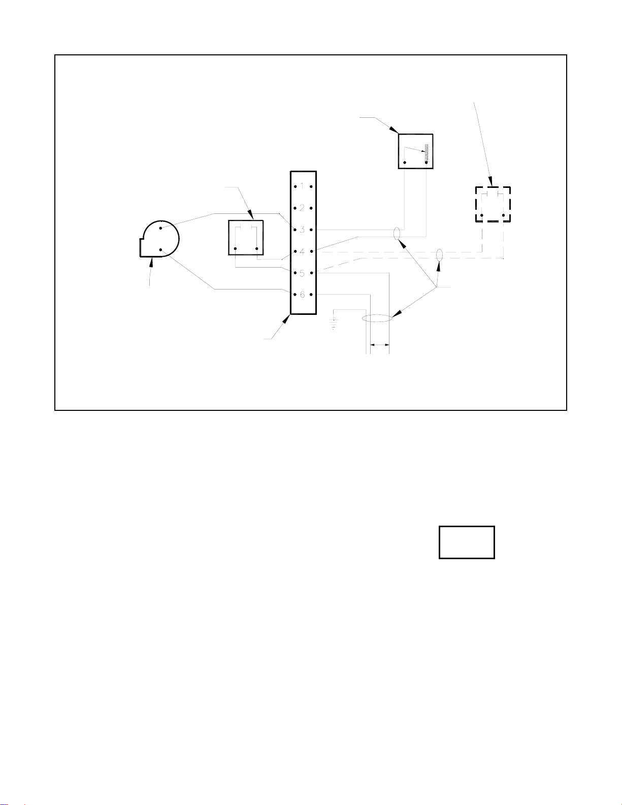
CABLÂGE POUR TOUS LES FOYERS (voir Figure 5)
1. Branchez les deux fils bleus de l'interrupteur thermique aux bornes 4 et 5 du bloc de bornes, tel
qu'indiqué sur les marqueurs de fil au bout de chaque fil.
2. Branchez les deux fils bleus du ventilateur interne aux bornes 3 et 6 du bloc de bornes tel
qu'indiqué sur les marqueurs de fil au bout de chaque fil.
3. Installez l'interrupteur de vitesse variable dans une boîte électrique ordinaire 2" x 4" à un endroit
pratique à l'extérieur du foyer.
4. En utilisant du filage de calibre 2/14 ordinaire, branchez l'interrupteur de vitesse variable aux
bornes 3 et 4 du bloc de bornes.
5. Il est possible d'installer un interrupteur ordinaire marche-arrêt pour commander manuellement le
ventilateur interne et ainsi désactiver l'interrupteur thermique. L'interrupteur manuel doit alors être
branché avec du filage de calibre 2/14 aux bornes 4 et 5 du bloc de bornes. Cela prend environ 20
à 30 minutes pour que le foyer dégage suffisamment de chaleur pour actionner l'interrupteur
thermique afin qu'il puisse, à son tour, activer le ventilateur. Avec l'interrupteur manuel, le

FO-FDHB5-N-2007-08
ventilateur peut être activé à votre guise. N'oubliez pas de remettre l'interrupteur manuel en position
arrêt afin que l'interrupteur thermique puisse arrêter le ventilateur lorsque le foyer refroidira.
6. Branchez les bornes 5 et 6 du bloc de bornes à un circuit de 110V avec du filage de calibre 2/14.
N'oubliez pas de brancher le fil de mise à la terre à la vis de mise à la terre du foyer, située juste à
côté du bloc de bornes.
7. Prenez soin de placer tous les fils de façon à ce qu'ils ne touchent pas à la boîte à feu.
Tiroir à cendres /
Ash pan
Équerre soudée /
Welded bracket
Patte droite de la boîte à feu /
Right firebox leg
Interrupteur thermique /
Thermal switch
Bloc de borne /
Terminal block
Figure 2 Installation de l'interrupteur thermique dans un foyer Onyx ou Opel /
Installation of the thermal switch in an Onyx or Opel fireplace
Interrupteur thermique /
Thermal switch
Bloc de bornes /
Terminal block
Ventilateur interne /
Internal blower
Sortie du ventilateur pointant
vers l'arrière /
Blower outlet towards the back
Persienne
inférieure
centrale /
Bottom
central
louver
Figure 1 Installation dans un foyer Delta /
Installation in a Delta fireplace

FO-FDHB5-N-2007-08
Interrupteur thermique /
Thermal switch
Bloc de bornes /
Terminal block
Ventilateur interne /
Internal blower
Sortie du ventilateur pointant
vers le haut /
Blower outlet pointing up
centrale /
Bottom
central
louver
Figure 4 Installation du ventilateur dans un foyer Onyx ou Opel /
Installation of the blower in an Onyx or Opel fireplace
Amortisseurs de vibrations /
Vibration rubber dampers
Figure 3 Préparation du ventilateur pour une installation dans un foyer Onyx ou Opel /
Preparation of the blower for an installation in an Onyx or Opel fireplace

FO-FDHB5-N-2007-08
Liste de contrôle / Check List:
1 Assemblage du ventilateur interne / Internal Blower Assembly (1.13.HB5.2.DNP)
1 Assemblage de l'interrupteur thermique / Thermal Switch assembly (1.13.H#.1.DNP)
1 Interrupteur de vitesse variable / Variable Speed Switch (940001)
1 Sac contenant 4 connecteurs en fourchette / 1 Bag containing 4 spade connectors (942006)
Notice d'installation et liste de contrôle / Instructions and check list INITIALES
INITIALS
Interrupteur de vitesse variable /
Variable speed switch
Optionnel: interrupteur manuel /
Optional: manual bypass switch
110V
Calibre #14 /
14 Gauge
Interrupteur thermique /
Thermal switch
Ventilateur interne /
Internal blower
Bloc de borne /
Terminal block
Blanc / White
Noir / Black
Figure 5 Diagramme de câblage /
Wiring Diagram
Table of contents
Languages: