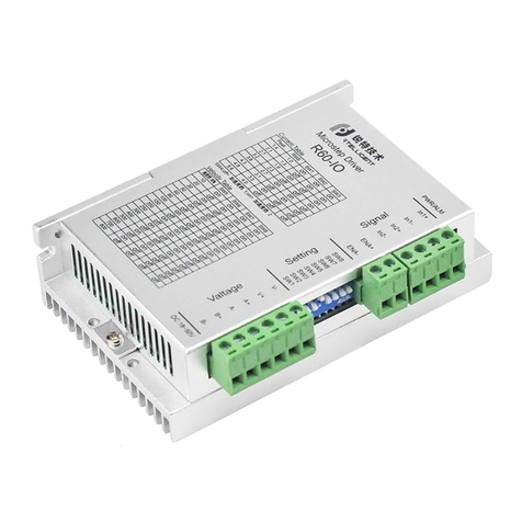
Rtelligent RS Series User manual

2020-10 version 3.0
RS series Servo System
Quick start guide

Please disconnect the power supply for more than 5 minutes before removing or
disassembling the driver, otherwise it may cause electric shock due to residual voltage.
Cautions
Please never touch the inside of the servo driver, otherwise it may cause electric shock
Please insulate the connection part of the power supply terminal, otherwise it may cause
electric shock.
Unless designated personnel, please do not set up, disassemble or repair, otherwise it may
cause electric shock or injury.
Please do not remove the cover, cables, connectors and optional accessories while the
power is on, otherwise it may cause electric shock and damage the drive.
Please follow the steps required by this manual for trial operation.
If an operation error occurs while the servo motor is connected to the machine, it will not
onlycause damage to the machine, but also sometimes cause personal accidents.
Please do not change the maximum speed value, except for special purposes. Inadvertent
change may damage the machine or cause injury.
When the power is turned on and for a period of time after the power is cut off, the heat sink
of the servo driver, the external braking resistor, and the servo motor may become hot.
Please do not touch it, otherwise it may cause burns. To prevent accidental contact with
hands or parts (cables, etc.), please take safety precautions such as installing an enclosure.
Please do not touch the rotating part of the servo motor while it is running, as this may
result in injury.
If the servo motor is installed on the supporting machine and starts to run, make sure that
the servo motor can be stopped at any time, otherwise you may get injured.
Please install a stop device on the machine side to ensure safety.
The brake of the servo motor with brake is not a stopping device to ensure safety. If a stop
device is not provided, it may cause injury.
If power is restored after a momentary power failure occurs during operation, the machine
may restart suddenly, so please do not approach the machine.
Please take measures to ensure that personal safety will not be endangered when
restarting, otherwise it may cause injury.
Please do not modify the product in any way, otherwise it may cause injury or
mechanical damage.
Please install the servo driver, servo motor, and external braking resistor on
non-combustible materials, otherwise it may cause a fire.
Between the power supply and the main circuit power supply of the servo driver
(L1, L2 for single-phase, L1, L2, L3 for three-phase), please connect an electromagnetic
contactor and a non-fuse circuit breaker. Otherwise, when the servo driver fails, the
large current cannot be cut off, which may cause a fire.
Please do not damage or pull on the cable, subject the cable to excessive force, put it
under heavy objects or clamp it. Doing so may result in electric shock, which may cause
the product to stop or burn out.
1
Thank you for using the RS series AC servo system! This operating manual
provides information about the RS series drivers and RSM series
motors. Before use, please read the manual carefully to ensure proper use!

Servo driver dimension drawing
Absolute battery box dimensions
Below 400W Below 1500W
Below 3000W
Model combination list
485 communication port
(CN4, CN5)
Panel operator
USB debugging port
(CN3)
Power supply input
Input and output signal
terminals (CN1)
Encoder interface (CN2)
Braking resistor
(can be external)
Motor interface
Grounding port
2

40
60
80
110
130
RSM-M04J0130A
RSM-M04J0330A
RSMA-M06J0630A
RSMA-M06J1330A
RSMA-M08J2430A
RSMA-M08J3230A
RSM-M11W4030A
RSM-M11W5030A
RSM-M11W6020A
RSM-M11W6030A
RSM-M13W5025A
RSM-M13W6025A
RSM-M13W7725A
RSM-M13W10025A
RSM-M13W15015A
RSM-M13W15025A
50W
100W
200W
400W
750W
1KW
1.2KW
1.5KW
1.2KW
1.8KW
1.3KW
1.5KW
2.0KW
2.5KW
2.3KW
3.8KW
RS 100(E)
RS 100(E)
RS 200(E)
RS 400(E)
RS 750(E)
RS 1000(E)
RS 2000(E)
RS 2000(E)
RS 2000(E)
RS 2000(E)
RS 2000(E)
RS 2000(E)
RS 2000(E)
RS 3000(E)
RS 3000(E)
RS 3000(E)
SES4-030
SES4-030
SES4-030
SES4-030
SES4-030
SES4-030
SEH4-030
SEH4-030
SEH4-030
SEH4-030
SEH4-030
SEH4-030
SEH4-030
SEH4-030
SEH4-030
SEH4-030
SMS-030
SMS-030
SMS-030
SMS-030
SMS-030
SMS-030
SMH-030
SMH-030
SMH-030
SMH-030
SMH-030
SMH-030
SMH-030
SMH-030
SMH-030
SMH-030
List of standard model combinations
Motor base Model Rated power Matching driver Encoder cable Power cable
* Driver with E is EtherCAT function
** Wiring is 3 meters as standard, other specifications please specify when ordering
Servo cable list
Naming of AC servo supporting cables
Cable of 80mm and below
Motor cable SMS-030
Color definition:
Red
110mm / 130mm Cable
Motor cable SMH-030
Color definition:
Brown
Cable series
S:220V AC servo
H:380V high-voltage servo
D:Low-voltage brushless servo
Cable category
E:Encoder extension cable
M:Motor power cable
Plug category
S:Plastic Amp Head
H:Aviation plugs
Number of cable cores
Power cable 4 cores can be omitted
Cable length
030: 3 meters
White Black Yellow-green
Blue Black Yellow-green
3

Vcc
Gnd
PS+
PS-
1
2
5
6
3
4
RS485-A
RS485-B
GND
——
——
——
——
——
1
2
3
4
5
6
7
8
L1
L2
P+
Br
U
V
W
PE
Motor model description
1
2
5
6
3
4
RSM Series Servo Motor
A:5 pole pairs,Ultra thin
none: 4 pole pairs
Motor inertia code
S: Small inertia M: Medium inertia
H: Large inertia
Motor flange size
06:60mm 13:130mm
Encoder resolution
J: 17bit magnetic encoder
H: 23bit optical encoder
G: 17bit magnetic Multi-turn absolute encoder
L: 23bit optical Multi-turn absolute encoder
W: 10000 lines optical encoder
Motor rated torque
13:1.3 Nm 150: 15 Nm
Oil seal or not
A: with oil seal
none: without
Brake or not
Z: With brake
Motor rated speed
30: 3000 rpm 15: 1500 rpm
Main circuit wiring definition
Functions
Input power
supply
Braking
resistance
Motor wiring
Terminal symbol Diagram
Description
Single-phase 220 VAC
When using an external braking
resistor, just replace the P+ and Br
wiring
Connect the motor extension cable
CN2 Encoder terminal wiring definition
Pin numbers
Reserved
Reserved
Diagram
Description
The encoder power supply is
provided by the driver
Encoder communication terminal
orange&white
orange
green&white
blue
blue&white
green
brown&white
brown
Pin num Color
Description Diagram
CN4,CN5 Communication 485 interface
Terminal symbol
4
Dual RS-485 interface

CN1-DB44 control signal interface definition
1
16
31
15
30
44
External
pulse
interface
Functions Signal Pin number Signal definition
PUL+
PUL-
DIR+
DIR-
24VPUL+
24VDIR+
IN1(SV-ON)
IN2(POT)
IN3(NOT)
IN4(ALMRST)
IN5(PULStop)
IN6(Home)
IN7(ZERStart)
IN8(EMEStop)
INCOM
Universal
input
interface
3
4
5
6
16
17
2
7
8
9
10
11
12
13
1
32
33
34
35
31
18
19
20
21
23
24
25
26
27
28
29
30
39
40
41
Differential pulse positive
Differential pulse negative
24V pulse positive
24V direction positive
Input 1
Input 2
Input 3
Input 4
Input 5
Input 6
Input 7
Input 8
Input common terminal
Output 1
Output 2
Output 3
Output 4
Output common ground
Output 5 positive
Output 5 negative
Output 6 positive
Output 6 negative
Encoder A+
Encoder A-
Encoder B+
Encoder B-
Encoder Z+
Encoder Z-
Single-ended EZ+
Single-ended EZ ground
Analog1+
Analog1-
Analog ground
Common
cathode
universal
output
interface
Differential
output
interface
Encoder
output
interface
Analog
input
interface
OUT1(SV-RDY)
OUT2(INP)
OUT3(ALM)
OUT4(ZERDO)
OUTCOM-
DFOUT5+(BRK+)
DFOUT5-(BRK-)
DFOUT6+
DFOUT6-
DFEA+
DFEA-
DFEB+
DFEB-
DFEZ+
DFEZ-
EZ
ECGND
ANGND
Default function
Servo enable
Positive limit
Negative limit
Alarm clear
Pulse prohibited
Origin input
Start homing
Emergency Stop
The servo is ready
Positioning completed
Alarm Output
Homing complete
Output ground
Brake positive
Brake negative
Reserved
Single-ended Z signal
Single-ended Z ground
Differential input, 5V
24V positive
Common anode or
common cathode is
supported under 24V,
and NPN or PNP mixed
use is not supported
The common cathode
output current below
24V does not exceed
50mA
The differential output
current below 24V does
not exceed 200mA
5V differential output
24V single-ended
output
-10V~+10V analog
input
Description
Differential direction positive
Differential direction negative
5
Analog2+
Analog2+
AN 1+
AN 1-
AN 2+
AN 2-
43
44

MODE
SET
Jog Test Operation
JOG
Forward
Ready
Error 2
Press Key 'UP’
Long Press KEY‘SET’
Short Press KEY‘MODE’ Press Key 'DOWN’
Reverse
Servo enable on,
turn off servo Enable signal
Display and panel operation
Functions
Mode/Return
Symbol Diagram
Description
Mode switch
Confirm operation
Shift key
Increase
Decrease
Confirm
Shift left
Switch up selection or increase value
Switch down selection or decrease
the value
Panel operation menu
Power-on initialization
display
Monitoring display
options
Parameter setting
Function operation
Monitoring display
Short press the S key
M key
M key
M key
Long Press KEY‘SET’
SAVE
READ
RESET
Operation progress of parameters
Short Press KEY‘MODE’
6
Press up and down keys to
select, SET key to view
Long press the SET key
to confirm and modify the parameters
Long press the MODE key to cancel the
modified parameters
Use the up and down keys to select, long
press the SET key to execute functions
Press up and down keys
to select, SET key to view

——
rpm
rpm
%
%
%
rpm
KHz
——
——
°
V
——
——
AL.100
AL.105
AL.110
AL.112
AL.113
AL.115
AL.120
AL.121
AL.125
AL.126
AL.200
AL.210
AL.211
AL.220
AL.221
AL.230
AL.240
AL.250
AL.252
Monitor State Content
ContentNO.Unit
Command unit(pulse)
Encoder unit(pulse)
Encoder unit
(pulse)
Encoder unit
(pulse)
cycles
Encoder unit
Run statement
speed of motor
speed command
motor torque
torque command
Run current
Position command counter
Position error
Pulse command speed
Input signal state
Motor mechanical position
Bus voltage
Encoder statement
encoder current value
alarm code
Position feedback counter
Pulse command frequency
Output signal state
Motor electrical angle
encoder cycles value
Common alarm & handling
Handling
NO. Fault content
Parameter read error Modify the P00.00 and reset
Encoder mismatch Confirm encoder style
IPM module overload Grounding correctly
Command overload
Motor thermal protection Adjust command setting,change motor
Internal voltage error Internal circuit error,change new driver
Encoder interference Check encoder shield
Encoder data error Check encoder wiring
Encoder disconnection
Encoder counter error
High Bus Voltage
Motor overspeed
Position feedback error
Brake inoperative
Low encoder supply power1
Low encoder supply power2
Mode error Confirm control mode setting
Low Bus Voltage
Change encoder battery
Reset encoder alarm
Limit fault
Decrease motor speed
Adjust load and speed
Check brake circuit
Check limit switch
7

Operation guide for position control mode
16
3
4
17
5
6
24VPUL+
24VDIR+
PUL+
PUL-
DIR-
DIR+
Pulse
Direction
9
1
2
7
24V+
24V-
18
19
20
21
23
24
25
26
27
28
32
33
34
29
30
35
31
CN2
Motor cable
U
V
W
PE
L1
L2
P+
Br
INCOM
Single-phase
220VAC
SV-ON
POT
NOT
ALMRST
12
13
10
11
8
……
Servo enable
Positive limit
Negative limit
Alarm clear
OUTCOM-
OUT4
ALM
INP
SV-RDY
BRK+
BRK-
DFOUT6+
DFOUT6-
DFEA+
DFEA-
DFEB+
DFEB-
DFEZ+
DFEZ-
EZ
ECGND
Encoder cable
Remarks:
1. The general input signal is a two-way optocoupler circuit, which can be
connected to a single common anode or a single common cathode (pin 1 is
the common terminal), and the common anode and common cathode cannot
be mixed.
2. The general output signal is a common cathode connection, and pin 31 is a
common ground. The maximum current of the output loop is 50mA. The
maximum current of the differential output signal output loop is 200mA,
which can be used to drive the relay switch.
3. Encoder output signal Z signal has single-ended output (pin29 and 30)
4. The input pulse frequency is up to 500KHz
8

Basic parameters of position control mode
Sample value
NO. Parameter name
Control mode
Rotation direction
Servo forced enable
IN1 function selection
IN1 polarity selection
IN2-8 function and polarity
OUT1 function selection
OUT1 selection
OUT2-6
Position command source
Pulse command type
Pulse command filter constant
Command smoothing time
pulses required for one revolution
First speed gain
The first speed integral time
First position gain
polarity
function and polarity
P01.01
P01.02
P02.00
P02.01
……
P02.32
P02.33
……
P03.00
P03.02
P03.03
P03.04
P03.06
P06.00
P06.01
P06.02
P01.00 0,position control mode
0, external IO control enable; 1, internal enable
Default 1 ,IN1 as servo enable
0, valid at low level; 1, valid at high level
……
……
0,External pulse input
Input pulse frequency limit
Default is 1 invalid
Default 10000
Rough adjustment of rigidity
Default 4 ,OUT1 as servo ready
0, valid at low level; 1, valid at high level
18
19
BRK+
BRK-
RS SERVO DRIVER
24V-
24V+
KA
-+
Remarks: 1. The output signal of brake control can only be specified as OUT5 or OUT6 port,
OUT5 is shown as default.
2. Motor brake cable has polarity, please pay attention to distinguish
Wiring diagram of holding brake
Servo driver
Relay
Servo motor with brake
9
0 or 1

18
19
20
21
23
24
25
26
27
28
32
33
34
29
30
35
31 OUTCOM-
OUT4
ALM
INP
SV-RDY
BRK+
BRK-
DFOUT6+
DFOUT6-
DFEA+
DFEA-
DFEB+
DFEB-
DFEZ+
DFEZ-
EZ
ECGND
39
40
9
1
2
7
12
13
10
11
8
A/D1
41
43
44 A/D2
AN1+
AN1-
Analog 1
-10~+10
24V+
24V-
INCOM
SV-ON
POT
NOT
ALMRST
︙︙
ANGND
AN2+
AN2-
Analog 2
-10~+10
CN2
U
V
W
PE
L1
L2
P+
Br
Operation guide for torque control mode
Single-phase
220VAC
Motor cable
Encoder cable
Alarm clear
Negative limit
Positive limit
Servo enable
Remarks:
1. The general input signal is a two-way optocoupler circuit, which can be
connected to a single common anode or a single common cathode (pin 1 is
the common terminal).
The common anode and common cathode cannot be mixed.
2. The general output signal is a common cathode connection, and pin 31 is a common
ground. The maximum current of the output loop is 50mA.
The maximum current of the differential output signal output loop is 200mA,
which can be used to drive the relay switch.
3. The output port identification is defined as the factory setting in the default position
mode of the driver, please reconfirm and assign the output port function when using.
4. Analog input specification is -10~+10V.
10

……
……
P02.74
P02.75
P02.76
P02.77
P01.00
P01.01
P01.02
P02.00
P02.01
……
P02.32
P02.33
……
P05.00
P05.02
P05.12
P05.14
P05.15
P05.13
P02.65
P02.67
P02.64
P02.66
P02.78
P02.79
P05.16
P05.17
P05.18
P05.19
Analog input processing procedure
Analog 1 input Filter
processing An1 input
voltage
Zero drift/
offset/dead
zone correction An2 processed
voltage
Command ratio
Analog 2 input Filter
processing An2 input
voltage
Zero drift/
offset/dead
zone correction An2 processed
voltage
Command ratio
Basic parameters of torque control mode
NO. Parameter name Sample value
Control mode
Rotation direction
Servo forced enable
IN1 function selection
IN1 polarity selection
IN2-IN8 function and polarity
OUT1 function selection
OUT1 selection
OUT2-OUT6 function and polarity
Channel A Torque command source
Torque command input source
Torque mode speed limit source
Torque mode forward speed limit value
Torque mode reverse speed limit value
Speed limit external analog channel selection
Analog 1 input filtering setting
Analog 1 zero drift correction value setting
The offset correction value of analog 1 setting
The dead zone range of analog 1 setting
The analog voltage - torque ratio setting
The analog voltage - speed ratio setting
The torque to reach the reference value setting
The torque to reach the effective offset value setting
The torque to reach the invalid offset value setting
The torque to reach the detection time setting
2,Torque control mode
0 or 1
O,External IO control enable;1,Internal enable
Default 1 ,IN1 as servo enable
0,Valid at low level ; 1,Valid at high level
Default 4 ,OUT1 as servo ready
1, channel A derived from analog channel 1 input
0, derived from channel A
0: internal given / 1: external analog channel input
0,Valid at low level ; 1,Valid at high level
P05.12=1, set P05.13=2 (channel 2).
P02.69 set channel 2 filtering
P02.71 set channel 2 zero drift
P02.68 set channel 2 offset
P02.70 Set channel 2 zero drift
Set the maximum output torque corresponding to 10V
Set the maximum speed limit value corresponding to 10V
11
This manual suits for next models
16
Other Rtelligent Servo Drive manuals
Popular Servo Drive manuals by other brands

JUNG ANTRIEBSTECHNIK U. AUTOMATION GMBH
JUNG ANTRIEBSTECHNIK U. AUTOMATION GMBH HM01-37 installation guide

SMAC
SMAC VLC-2-EIP user manual

Moons'
Moons' M2DC Series Hardware manual

Smitec
Smitec COSMOS 301 Series Installation, use and maintenance manual

THORLABS
THORLABS TBD001 user guide

Emerson
Emerson SP1201 installation guide