Arcus TITAN-SVX User manual

TITAN-SVX Operation Manual page 1 Rev 4.05
OPERATION MANUAL
Revision 4.05
TITAN-SVX
SERVO MOTOR CONTROLLER-DRIVER

TITAN-SVX Operation Manual page 2 Rev 4.05
COPYRIGHT© 2017 ARCUS,
ALL RIGHTS RESERVED
First Edition, Jan 2017
ARCUS TECHNOLOGY copyrights this document. You may not reproduce or translate
into any language in any form and means any part of this publication without the written
permission from ARCUS.
ARCUS makes no representations or warranties regarding the content of this document.
We reserve the right to revise this document any time without notice and obligation.

TITAN-SVX Operation Manual page 3 Rev 4.05
Table of Contents
1. INTRODUCTION ........................................................................................................................................ 5
1.1. TECHNICAL FEATURES ....................................................................................................................................6
2. GENERAL OPERATION OVERVIEW ........................................................................................................ 7
2.1. PULSE MODE.....................................................................................................................................................7
2.2. CONTROL MODE...............................................................................................................................................8
2.2.1. Position Value .............................................................................................................................................. 8
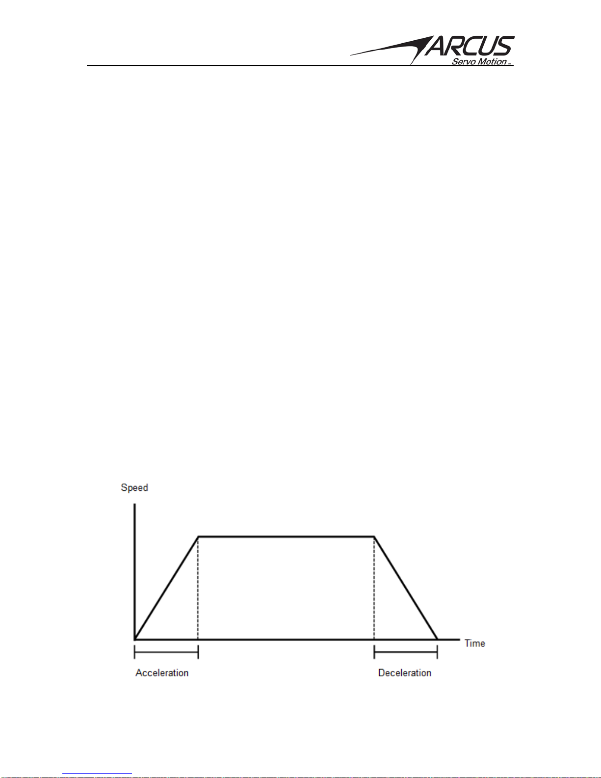
2.2.2. Motion Profile .............................................................................................................................................. 8
2.2.3. Homing............................................................................................................................................................ 9
2.2.4. Limits .............................................................................................................................................................11
2.3. MOTOR POWER .............................................................................................................................................11
2.4. JOG MOVE .......................................................................................................................................................11
2.5. STOPPING ....................................................................................................................................................... 12
2.6. POSITIONAL MOVES......................................................................................................................................12
2.7. MOTOR STATUS............................................................................................................................................. 12
2.8. FAULT STATUS............................................................................................................................................... 12
2.9. DIGITAL INPUTS /OUTPUTS .......................................................................................................................13
2.10. ANALOG INPUTS ......................................................................................................................................... 14
2.11. JOYSTICK CONTROL .................................................................................................................................... 14
2.12. CLOSED LOOP CONTROL GAINS ............................................................................................................... 15
2.12.1. P-Gain..........................................................................................................................................................15
2.12.2. V-Gain..........................................................................................................................................................15
2.12.3. I-Gain...........................................................................................................................................................15
2.12.4. C-Gain..........................................................................................................................................................15
2.13. DYNAMIC GAINS ......................................................................................................................................... 15
2.14. FORCE CONTROL ........................................................................................................................................ 16
2.15. STANDALONE PROGRAM SPECIFICATION ............................................................................................... 18
2.15.1. Standalone Program Specification ...............................................................................................19
2.15.2. Multi-thread / multi-tasking............................................................................................................19
2.15.3. Standalone Subroutines .....................................................................................................................19
2.15.4. Standalone Variables...........................................................................................................................19
2.15.5. Math Operations....................................................................................................................................20
2.15.6. Standalone Run On Boot-Up.............................................................................................................20
2.15.7. Storing Standalone Program to Flash.........................................................................................20
2.15.8. Standalone Command Set..................................................................................................................21
2.15.9. Conditional Statements ......................................................................................................................24
2.15.10. Example Standalone Programs....................................................................................................25
3. SERIAL COMMUNICATING COMMANDS................................................................................................29
3.1. STATUS COMMANDS ..................................................................................................................................... 29
3.2. LED COMMANDS........................................................................................................................................... 29
3.3. MOTION COMMANDS.................................................................................................................................... 30
3.4. GAIN COMMANDS.......................................................................................................................................... 30
3.5. STANDALONE PROGRAM COMMANDS ....................................................................................................... 31
3.6. LIMIT COMMANDS......................................................................................................................................... 31
3.7. DIGITAL IO COMMANDS............................................................................................................................... 32
3.8. VARIABLE COMMANDS................................................................................................................................. 32
3.9. COMMUNICATION COMMANDS ................................................................................................................... 32

TITAN-SVX Operation Manual page 4 Rev 4.05
3.10. FAULT MONITORING COMMANDS ...........................................................................................................33
3.11. MISCELLANEOUS COMMANDS .................................................................................................................. 33
3.12. TREND MONITORING COMMANDS...........................................................................................................34
3.13. FORCE CONTROL COMMANDS .................................................................................................................. 34
4. SOFTWARE OVERVIEW ..........................................................................................................................35
4.1. SOFTWARE INSTALLATION.......................................................................................................................... 35
4.1.1. TITAN Directory .......................................................................................................................................37
4.2. COMMUNICATION AND SETUP REQUIREMENTS.......................................................................................38
4.3. STARTING THE TITAN-SVX UI SOFTWARE ............................................................................................ 39
4.4. COMMUNICATION.......................................................................................................................................... 40
4.4.1. USB/Serial Communication ................................................................................................................41
4.4.2. Ethernet Communication.....................................................................................................................44
4.5. MOTOR............................................................................................................................................................ 45
4.5.1. Motor Information...................................................................................................................................46
4.5.2. Position Sensor Parameters ................................................................................................................46
4.5.3. Motor Electric Parameters ..................................................................................................................47
4.5.4. Motor Mechanical Parameters ..........................................................................................................47
4.5.5. Motor Database Wizard........................................................................................................................48
4.6. TUNING ........................................................................................................................................................... 57
4.6.1. Mechanical Parameters ........................................................................................................................59
4.6.2. Mechanical Parameter Auto Detect Wizard................................................................................60
4.7. CONFIGURATION ...........................................................................................................................................64
4.7.1. Mechanical Parameters ........................................................................................................................65
4.7.2. Controller Mode Setup...........................................................................................................................65
4.7.3. Pulse Mode Setup......................................................................................................................................66
4.7.4. Special Configurations...........................................................................................................................67
4.7.5. Error Conditions / ESTOP Input........................................................................................................67
4.7.6. Analog Input Joystick Related Parameters ..................................................................................68
4.7.7. Position Related Parameters ..............................................................................................................68
4.7.8. Ethernet Socket Communication Settings ....................................................................................69
4.7.9. Power Up State..........................................................................................................................................69
4.8. PARAMETERS.................................................................................................................................................70
4.9. TEST DRIVE.................................................................................................................................................... 72
4.9.1. Control Mode..............................................................................................................................................73
4.9.2. Pulse Mode...................................................................................................................................................84

TITAN-SVX Operation Manual page 5 Rev 4.05
1. Introduction
The TITAN-SVX is an advanced single-axis closed loop servo driver-controller that
supports various types of motors that are commonly used in the automation industry:
- 2 Phase Stepper Motor
- 3 Phase Brushless Rotary Servo Motor
- 3 Phase Brushless Linear Servo Motor
- DC Voice Coil Motor
In addition to the advanced servo motion control technology, the TITAN-SVX also has a
number of advanced control technologies including force control, joystick control,
dynamic gains, standalone programming, and many more. Voltage, current,
temperature, and position monitoring allow for the TITAN-SVX to examine system trends
and allow for preventative measures to reduce system down time.
TITAN-SVX is a true intelligent motion controller driver that enables and readies the
future in the field of Smart Factory and Automation and Industrial Internet of Things.

TITAN-SVX Operation Manual page 6 Rev 4.05
1.1. Technical Features
- Communication using RS-485 multi-drop network:
•115200 bps, 8N1
Communication Protocol supported:
•TITAN-ASCII
•TITAN-ASCII with CRC
•MODBUS-ASCII
•MODBUS-RTU
- 100Mbps Ethernet communication using ASCII over TCP/IP1
- USB communication using VCP
- Standalone programmable using Arcus A-SCRIPT language with support of 3
multi-thread programs
- Closed Loop Driver Specifications:
•24-48 VDC
•8.0 Amp max peak current setting
•1 MHz max pulse support (in Pulse Mode)
- Multiple types of motor support:
•2 Phase Bipolar Stepper Motors
•3 Phase Brushless Rotary Servo Motors
•3 Phase Brushless Linear Servo Motors
•DC Voice Coil Motors
- Configurable in following modes:
•Pulse Mode - digital pulse control using pulse/dir or CW/CCW
•Control Mode – internal motion profile generation with motion
sequence control from internal standalone programming.
- Opto-isolated Digital IO:
•8 bits of digital inputs
•3 bits of digital outputs
- 1 x 12-bit analog input
Joystick control
- A/B/Z differential encoder inputs with A/B/Z single ended encoder signal
outputs
- UVW Hall sensor digital inputs
- Control Mode Features:
•Homing routines using combination of Home/Limit/Z Index
•Soft and Hard Limit Protection.
•Over-current/Over-voltage/ Under voltage/Temperature/Position Error
fault detection
•Force/Torque Control
•Dynamic gains
1Only applicable to TITAN-SVX-ETH model

TITAN-SVX Operation Manual page 7 Rev 4.05
2. General Operation Overview
All commands described in this section refer to ASCII commands sent over RS485,
USB, or Ethernet. Corresponding standalone commands are details in the Standalone
Command Set section. A full list of valid ASCII commands can be found in section 3.0.
The TITAN-SVX can be used in Pulse Mode or Control Mode.
Pulse Mode is used when the control position signals are sent from an external motion
controller that generates pulse and direction signals (or CW/CCW signals). In Pulse
Mode, standalone programming is supported but motion related commands are not
supported.
Control Mode is used when the motion control and motion profiling is done internally by
the TITAN-SVX controller. Control Mode supports standalone programming with all
motion commands.
2.1. Pulse Mode
In order to use the controller as pulse mode, TITAN-SVX must be configured as Pulse
Mode. Please refer to the Configuration section of the TITAN-SVX Windows UI program
to set the controller to the Pulse Mode.
In Pulse Mode, the following digital inputs and outputs are used:
INPUTS:
Pulse (CW) – sets the target position of the motion.
Dir (CCW) – sets the direction of the motion
Enable – enables the servo power to the motor
Clear – clears any fault
Reset – resets the internal position counter to zero
OUTPUTS:
In Position – when the difference in target and actual position value is
within the in-position amount, this output turns on.
Alarm – when the TITAN-SVX goes into error (such as position range
error, stall current error, over temperature error, etc.) this output turns
on. To clear the alarm state, toggle the Clear input or the Enable
input.
Polarity of the inputs and outputs can be configured as active low or active high. Please
refer to the Configuration section of the manual for various settings.

TITAN-SVX Operation Manual page 8 Rev 4.05
2.2. Control Mode
In order to use the controller in Control Mode, TITAN-SVX must be configured as Control
Mode. Please refer to the Configuration section of the TITAN-SVX- Windows UI program
to set the controller to the Control Mode.
In Control Mode, following digital inputs are used:
INPUTS:
+LIM (DI6) – Plus Limit Input
HOME (DI7) – Home input
-LIM (DI8) – Minus limit input
All other remaining digital inputs and outputs (5 digital inputs and 3 digital outputs) are
available as general purpose use.
In Control Mode, the limit inputs can be disabled and used as general purpose inputs.
2.2.1. Position Value
By default, the position values of TITAN-SVX are in encoder counts. The EX command
can be used to query the current encoder position. The user must convert the encoder or
pulse counts to actual position unit such as mm, inch, or degrees.
For example, consider TITAN-SVX driving a stepper motor with 16,000 encoder counts
per rev that is connected to a ball screw linear drive with pitch of 10mm. In this linear
system, 1mm move will be 1,600 encoder count of the motor.
During operation, the current target position of the TITAN-SVX can be read using the
POSD command. Additionally the current position error can be read using the PERR
command. The response of both commands will be in units of encoder counts.
2.2.2. Motion Profile
The TITAN-SVX uses a trapezoidal velocity profile as shown in Figure 2.0.
Figure 2.0

TITAN-SVX Operation Manual page 9 Rev 4.05
Target speed can be set using the HSPD command. The speed value is in either in RPM
or mm/sec depending on whether the type of motor is configured as rotary or linear.
Note that all rotary motors are configured as RPM and all linear motors are configured
as mm/sec speed value.
Speed parameters can be changed to encoder counts/sec in order to achieve slower
motion. See the configuration section of the TITAN-SVX software in section 4 to make
this setting. The lowest allowable speed setting will be 1. Depending on the mode, this
will correspond to 1 RPM (mm/sec) or 1 encoder count/sec.
Target acceleration can be set using the ACC command. Acceleration values are in
either RPM/sec or mm/sec2depending on the setting as rotary or linear. Acceleration
represents the rate of increase of the speed, or the slope of the speed/time chart as
shown in figure 6.0. Note that the higher the acceleration value, the steeper the
speed/time graph (slope) will be and quicker to reach the target speed.
For short duration profiles where the speed cannot be reached, the controller
automatically uses a triangle profile, and high speed will not be reached.
Acceleration value is used for both acceleration and deceleration of the motion profile.
2.2.3. Homing
The TITAN-SVX has various homing routines using the home, limit, and encoder index
inputs. To perform a homing routine, the homing mode must be selected using the
HMODE command. See table 2.0 for details.
Value
Description
0
Positive direction using home sensor
1
Negative direction using home sensor
2
Positive direction using positive limit sensor
3
Negative direction using negative limit sensor
4
Positive direction using home sensor and following
encoder index
5
Negative direction using home sensor and following
encoder index
6
Positive direction using positive limit sensor and
following encoder index
7
Negative direction using negative limit sensor and
following encoder index
8
Positive direction using encoder index
9
Negative direction using encoder index
Table 2.0
Once a homing mode is selected, the HOMEX command will perform the homing
routine.

TITAN-SVX Operation Manual page 10 Rev 4.05
Hard stop homing is also available by using a standalone program that senses the motor
current or position error. A sample standalone program is included in the TITAN-SVX
software installation.
The following example shows the example of home search in positive direction using the
home input plus encoder index input.
Figure 2.1
In the homing example in figure 2.1, the following are the points where the homing can
start:
A. Homing is initiated in positive direction and rising edge of the home signal is
detected. Index is searched as soon as the rising edge of the home signal is
detected.
B. Homing starts in home input on state. The homing routine moves the motor
out of the home sensor and search back to find the rising edge of the home
sensor. Encoder index sensor is searched as soon as the rising edge of the
home sensor is detected
C. Homing starts in positive direction and positive limit switch is detected.
Motion moves out of the limit switch and searches for the rising edge and
then falling edge of the home sensor and then moves back to find the rising
edge of the home sensor. Encoder index searched as soon as the rising
edge of the home sensor is detected.
The above example shows the homing routine that will always find a consistent home
position.

TITAN-SVX Operation Manual page 11 Rev 4.05
2.2.4. Limits
TITAN-SVX has both software and hardware limit monitoring.
Software limit function can be enabled and disabled using the SLIMON command. The
positive and negative software limit position values can be set in the Configuration
Section or by using the SLIMPOS and SLIMNEG commands.
The hardware limit can be enabled and disabled in the Configuration section.
The following actions are available when either soft limit or hard limit is triggered. Action
is determined by the value of the LIMPRO command.
Value
Description
0
Disable Motor
1
Immediate stop with servo on
Table 2.1
When limit function is enabled and the limit input is triggered during motion, the motion
state goes into an error state. If the standalone program is running and error occurs, the
program state goes into error state. Error state must be cleared before any further
motion can be performed or program can be run.
2.3. Motor Power
The motor can be enabled or disabled during operation. The SVON command will
enable the motor and the SVOFF command will disable the motor. By default, the
TITAN-SVX will power on with the motor disabled. Settings in the Configuration section
of the TITAN-SVX GUI allow for the motor to be enabled on power up.
If a stepper motor is being used, an open loop hold option is available to keep the motor
steady while idle. Use the OLPHOLD command to activate this feature. When enabled,
the motor will not servo while idle. This option is not available for BLDC or DC motors.
Value
Description
0
Deactivated. Full time closed loop servo
1-100
Percentage current hold when enabled and idle
Table 2.2
2.4. Jog Move
A jog move is used to continuously move the motor without stopping. The JOGXP
command will jog the motor in the positive direction and the JOGXN command will jog
the motor in the negative direction. Once this move is started, the motor will only stop if a
limit condition is activated during motion or a stop command is issued.
If a motion command is sent while the controller is already moving, the command is not
processed. Instead, an error response is returned.

TITAN-SVX Operation Manual page 12 Rev 4.05
2.5. Stopping
When the motor is performing any type of move, motion can be stopped using the
STOPX command. The stop command will use the value in the ACC command as the
deceleration for the stop.
2.6. Positional Moves
The TITAN-SVX can perform moves to a defined position. The target position will be in
terms of encoder counts. Use the command X=[target] to perform a positional move.
For example, the X=1000 command will move the motor to encoder position 1000.
If a motion command is sent while the controller is already moving, the command is not
processed. Instead, an error response is returned.
2.7. Motor Status
Motor status can be read anytime by reading the response to the MST command. The
following is the bit representation of motor status.
Bit
Description
0
Enabled
1
In Position
2
Moving
3
In Fault
Table 2.3
2.8. Fault Status
If the motor is in a fault condition, as indicated by the MST command, the fault status
can be read from the response to the FLT command. The following is the bit
representation of fault status.
Bit
Description
0
Negative Limit Error
1
Positive Limit Error
2
Position Error
3
Current Error
4
Hall Sensor Error
5
Over Current Error
6
Over Voltage Error
7
Under Voltage Error
8
Over Temperature Error
9
Motor Connection Error
10
Emergency Switch On
11
Encoder Error
Table 2.4
The ECLEARX command can be used to clear a fault condition.

TITAN-SVX Operation Manual page 13 Rev 4.05
2.9. Digital Inputs / Outputs
TITAN-SVX module comes with 8 digital inputs and 3 digital outputs. Depending on the
mode of the TITAN-SVX, Pulse Mode or Control Mode, digital inputs and outputs are
used in various ways.
Pulse
Mode
Control
Mode
Pulse Mode Description
Control Mode
Description
PUL(CW)
DI1
Pulse Input
Digital Input 1
DIR(CCW)
DI2
Dir Input
Digital Input 2
ENA
DI3
Enable Input
Digital Input 3
CLR
DI4
Clear Fault Input
Digital Input 4
RST
DI5
Reset Input (EMG)
Digital Input 5 (EMG)
DI6
+LIM
Digital Input 6 (Not Used)
+ Limit Input
DI7
HOME
Digital Input 7 (Not Used)
Home Input
DI8
-LIM
Digital Input 8 (Not Used)
- Limit Input
ALM
DO1
Alarm Output
Digital Output 1
DO2
DO2
Digital Output 2 (Not Used)
Digital Output 2
INP
DO3
In Position Output
Digital Output 3
Table 2.5
The DIN command will return the status of all 8 available digital inputs in a bitwise
assignment.
The DOUT command can be used to set or read the value of all 3 digital outputs in a
bitwise assignment.
+L and –L can be disabled as limit switch input and can be used as general purpose
inputs. Check the Configuration section of the Windows program.
In Pulse Mode, PUL and DIR (CW/CCW) are used for position input and ENA is used for
enabling and disabling the power to the motor.
CLR (or DI4) is used for clearing any faults. RST (or DI5) is used to reset the position
and error. DI5 can be configured as Emergency input. When EMG is enabled, the
triggering of DI5 will disable the motor immediately.
DI6, DI7, and DI8 are not used in Pulse mode.
In Pulse Mode, there are 3 digital outputs. ALM is turned on when there is any fault in
the driver. INP is turned on if the target position is within the in-position tolerance value.
Digital output 2 is a general purpose digital input.
Polarity of the digital outputs and inputs can be configured to be active high or active low.
See Configuration section of the software, detailed in section 4.

TITAN-SVX Operation Manual page 14 Rev 4.05
2.10. Analog Inputs
The AIN command will retrieve the current 5V 12-bit analog input status of the TITAN-
SVX. The return value can range from 0 to 4095. A value of 0 will correspond to 0V and
4095 will correspond to 5V.
2.11. Joystick Control
A joystick control is available using the 12-bit analog input. The analog input value can
range from 0 to 4095.
The joystick operation will move the motor in the positive or negative direction based on
the value of the analog input. The maximum allowable speed of the joystick operation is
defined by the AJMS command.
Parameters for the low deadband value and the high deadband value will be defined by
the AJDBL and AJDBH commands respectively. While the analog input is between
these two values, joystick operation will not move the motor. The bandwidth parameter,
defined by the AJBW command, will determine the slew rate of the motor as the analog
input increases or decreases beyond the deadband zone.
The relationship between the deadband zone and bandwidth can be seen in the
figure below.
Figure 2.2
The soft limits for joystick control can be implemented using the standard soft limit
feature.

TITAN-SVX Operation Manual page 15 Rev 4.05
2.12. Closed Loop Control Gains
TITAN-SVX has the following simplified gain settings available.
•P Gain – Position gain.
•V Gain – Velocity gain.
•I Gain – integral gain
•C Gain – current gain
All the gains have range from 0 to 100. The simplified gain values are derived using
special formulas that are converted to normalized values ranging from 0 to 100. Value
of 0 represents weak gain value and 100 represents strong gain values.
2.12.1. P-Gain
P-Gain is also known as position gain. Position gain determines the firmness of the
closed loop control. P-Gain is similar to Proportional gain in the PID Loop. Use the
PGAINF command to access the P-Gain.
2.12.2. V-Gain
V-Gain is also known as velocity gain. Velocity gain is mainly used to reduce the
velocity error and mainly used to reduce overshoots in the vibration. V-Gain is similar to
Derivative gain in the PID Loop. Use the VGAINF command to access the V-Gain.
2.12.3. I-Gain
I-Gain is also known as integral gain. Integral gain is mainly used to reduce steady state
position error. I-Gain is similar to Integral gain in the PID Loop. Use the IGAINF
command to access the I-Gain.
2.12.4. C-Gain
C-Gain is also known as current gain. Current gain is mainly used for the current control
and consists mainly of proportional and integral gain of the current control. Use the
CGAINF command to access the C-Gain.
2.13. Dynamic Gains
Dynamic gain can be used to change the behavior of the closed loop servo depending
on motor speed. Applications may require a higher responsiveness from the servo as the
speed of the motor increases.
A low speed gain and a high speed gain can be defined using the DGLGAIN and
DGUGAIN respectively. The low speed used for the low speed gain setting can be set
using the DGLSPD command. The high speed used for the high speed gain setting can
be set using the DGUSPD command.
There is a linear relationship between the low and high speed gains as the speed
transitions from low to high speed. See the graph in figure 2.3 for details.

TITAN-SVX Operation Manual page 16 Rev 4.05
Figure 2.3
Dynamic gain can also be based on the actual or target velocity. The DGTYPE=0
command will use the profile velocity and the DGTYPE=1 command will use the actual
velocity.
The DGENA command can be used to enable (1) or disable (0) the dynamic gain
feature.
2.14. Force Control
Force, or torque, generated by an electric motor is equal to the motor constant Kt
multiplied by the motor current as represented by the following equation.
Force (or Torque) = Kt * Current
By monitoring and controlling the motor current, the TITAN-SVX is able to perform
various types of force control operations. Titan-SVX has a built-in force control routine
with the following steps.

TITAN-SVX Operation Manual page 17 Rev 4.05
Figure 2.4
Step Description
Relevant Variables
1
Force control starts from initial position
(FCPA). If not in this position at the start of the
routine, the motor is moved to this location at
high speed (FCVC) and acceleration (FCAC).
FCPA – Initial Position
FCVC – Velocity to PA
FCAC – Acceleration to PA
2
Motor is moved to the start of search position
(FCPB)at high speed (FCVA) and
acceleration (FCAA). FCCA defines the max
current used for the move to FCPB.
FCPB – Start Search Position
FCVA – Velocity to PB
FCAA – Acceleration to PB
FCCA – Maximum current used moving to PB
3
From FCPB position, the motor is decelerated
to velocity FCVB and moved until the current
trigger is detected, at position FCPT. Once the
trigger is detected, the following two force
operations are performed in parallel:
•Decelerate to a stop from the
detection point or move to position
FCDP further down maintaining the
force. Move further down is performed
in case the detected point is pushed
down and the force needs to be
maintained.
•Countdown timer is started in order to
maintain force for the set duration
amount.
FCPT – Current trigger position value
FCVB – Velocity moving to FCPT
FCAB – Deceleration used after finding FCPB
FCCB – Maximum current used during the
search
FCCC – Trigger current to detect FCPT
FCCF – Current used to apply continuous force
after detecting FCPT
FCDP – Additional delta position move from the
trigger position FCPT for applying continuous
force. Motor may not move during FCDP move.
FCPM – Maximum position to move before
determining trigger not found.
4
Once the continuous force operation and
countdown timer operation are satisfied, the
motor is moved away from the current position
by the position amount FCDL. High speed
FCVB and acceleration FCAB are used.
FCVB – Velocity used for lift move
FCAB – Acceleration used for lift move
FCDL – Lift movement amount from current
location
FCCF – Current used during lift move
5
Motor is moved back to the initial position
FCPA at high speed (FCVC) and acceleration
(FCAC).
FCPA – Initial Position
FCVC – Velocity to PA
FCAC – Acceleration to PA
Table 2.6

TITAN-SVX Operation Manual page 18 Rev 4.05
The Force Control Mode command FCMODE allows for the following force control
options.
Bit
Description
0
Filter Current – while the motor is moving in search of the current trigger
position, the moving average filter can be enabled to reduce noise in the motor
current reading. Note that enabling filter current will reduce the sensitivity.
1
Wait Acknowledge – when the motor current trigger point is detected, the
acknowledge command is expected before performing the lift move and moving
back to the initial position. The acknowledge command can come from either
the host controller or by digital input.
2
DIO Control – Digital inputs and output are used for the Force Control.
Table 2.7
Digital input and outputs can be used for the Force Control routine. To use digital
IO for the Force Control, enable bit 2 of the force control mode parameter
FCMODE.
See the table below for the digital IO assignment in regards to the Force Control
feature.
I/O
Description
DI1
Start the force control routine (active high). Also used to issue acknowledge
command (falling edge) if enabled by the FCMODE parameter.
DI2
Abort the force control routine (active high). When triggered during the force
control routine, the motor is immediately moved back to the initial position
FCPA using FCVC and FCAC.
DO1
Force control routine status. High signal indicates the force control routine is in
progress. Low indicates the force control routine is completed.
DO2
Waiting for acknowledge. High signals means that force trigger is detected and
waiting for the acknowledge signal.
DO3
Found trigger. High signal means the force trigger is found.
Table 2.8
2.15. Standalone Program Specification
Standalone programming allows the controller to execute a user defined program that is
stored in the internal memory of the TITAN-SVX. The standalone program can be run
independent of host communication.
Standalone programming can be used in both Pulse Mode and Control Mode.Note that
in Pulse Mode, motion commands are not supported since the motion is controlled using
the digital inputs.
Standalone programs are written, compiled, and downloaded to the TITAN-SVX using
the GUI program. Standalone program also can be uploaded from TITAN-SVX.

TITAN-SVX Operation Manual page 19 Rev 4.05
The standalone program can be stored in the flash and auto start can be enabled so that
the standalone program run on controller power up.
The TITAN-SVX supports up to three separate standalone programs simultaneously
which is also known as multi-threading or multi-tasking. For example, program 0 can be
used to perform motion related functions. Program 1 can be used for digital IO
monitoring and triggering. Program 2 can be used for dynamic gain control.
2.15.1. Standalone Program Specification
Memory size: max total 1000 standalone lines (all 3 programs combined).
2.15.2. Multi-thread / multi-tasking
The TITAN-SVX supports the simultaneous execution of all three standalone programs.
2.15.3. Standalone Subroutines
The TITAN-SVX has the capability of using up to 32 separate subroutines. Subroutines
are typically used to perform functions that are repeated throughout the standalone
program. Note that subroutines can be shared by multi-threads of standalone programs.
Standalone programs can jump to subroutine in the standalone program. The
subroutines are referenced by their subroutine number [SUB 1 - SUB 32]. If a
subroutine number is not defined, the controller will return with an error.
2.15.4. Standalone Variables
The TITAN-SVX has 100 32-bit signed integer standalone variables available for general
purpose use. They can be used to store values, perform basic calculations, and support
integer operations. Floating point values are not supported. Note that in the math
operations, floating point calculation is done but the values are saved as integer whole
number values.
Any read commands, variables, or constant values can be assign to a variable.
Variables are initialized to zero on power up. Table 2.9 are values that can be assigned
to a variable
Argument
Description
Example
[CONST]
Constant Value
V1=200
V[var num]
Variable
V1=V2
MSTX
Motor Status
V1=MSTX
PROBEST
Probe Status
V1=PROBEST
CUR
Motor Current
V1=CUR
ERX
Position Error
V1=ERX
PX
Profile Position
V1=PX
EX
Actual Encoder Position
V1=EX
SPDX
Actual Speed
V1=SPDX
DI
Digital Inputs (bit 0-7)
V1=DI
DI[val]
Digital Input Bit
V1=DI2
DO
Digital Outputs (bit 0-2)
V1=DO
DO[val]
Digital Output Bit
V1=DO1
Table 2.9

TITAN-SVX Operation Manual page 20 Rev 4.05
2.15.5. Math Operations
The following math operations are available for use in the standalone programming:
Operator
Description
Example
+
Integer Addition
V1=V1+2
-
Integer Subtraction
V1=V2-V3
*
Integer Multiplication
V1=V2*200
/
Integer Division (round down)
V1=V3/2
%
Modulus
V1=V2%5
>>
Bit Shift Right
V1=V2>>2
<<
Bit Shift Left
V1=V2<<2
&
Bitwise AND
V1=V2&7
|
Bitwise OR
V1=V2|8
~
Bitwise NOT
V1=~V2
Table 2.10
2.15.6. Standalone Run On Boot-Up
Standalone programs can be configured to run on controller power up. Refer to the
Windows program on Test Drive window.
Important Note: When running on power up, be careful that the program does not move
the motor in uncontrolled manner and damage the system.
2.15.7. Storing Standalone Program to Flash
Standalone programs need to be stored on the flash of the TITAN-SVX, which allows the
program to be preserved after powering down the controller. This is also required if the
program is to be started from power up.
Important Note: When standalone programs (or parameters) are stored to flash
memory, the motor servo will be turned off.
Program with comments can also be stored to the flash. Please refer to the Test Drive
section of the software, detailed in section 4.
Other manuals for TITAN-SVX
1
Table of contents
Other Arcus Servo Drive manuals
Popular Servo Drive manuals by other brands

MICROPHASE
MICROPHASE DC One DC1C Series Service manual

Rockwell Automation
Rockwell Automation Reliance electric GV3000/SE installation manual

Baldor
Baldor Flex+DriveII installation manual

National Instruments
National Instruments NI 9516 Operating instructions and specifications

Inovance
Inovance SV660F Series installation guide

Technosoft
Technosoft iPOS4808 BX-CAT-STO Technical reference