RTR Energia 12kVAr User manual

RTR ENERGÍA, S.L.
Pol. Ind. Pinto – Estación
28320 Pinto (Madrid) – ESPAÑA
Tel.: (+3 ) 916 916 612 Fax: (+3 ) 916 912 257
Microprocessor-Controlled Capacitor
Switching Thyristor Mod les
Technical User’s
Man al
Date: 08/11/2016
Version: 4

TECHNICAL USER´S MANUAL
1
Thyristor modules
WARNINGS & SAFETY PRECAUTIONS
•Check your power cables and connections for damage before powering up the module. If
the cables are damaged, do not power it up.
•Power cables should not pass over the module.
•To replace the module, the power must be switched off and capacitors must be
completely discharged.
•Do not exceed the nominal ratings specified in the technical specifications.
•Do not touch the modules with bare and/or wet hands while it is on.
•Make sure that the power is turned off when cleaning. Use a dry cloth to clean the
module.
•Do not operate the module under or above the specified voltage ratings.
•The module must be vertically mounted on the mounting plate.
•Check cabling and connections before powering up.
Ca tion: Life-threathening voltage levels may remain in the capacitors long after
the power is switched off. Make s re capacitors are completely discharged
before to ching the mod le.

TECHNICAL USER´S MANUAL
2
Thyristor modules
Table of Contents
Warnings and Safety Preca tions………………….…………………..………..
Table of Contents……………………………………….…………………………….…
1Introd ction………………………………………….……………………….……..
1.1 General Description……………………………………….………
1.2 Application Areas….……………………………………..……….
2Technical Specifications……………………………………………………….
3Set p……..……………………………………………………………..……......….
3.1 Prerequisites for Setup…….………………...…………………
3.2 Installation………………….………………….……..……………..
3.3 Wiring Diagrams..................………….………………………
3. Ready for Start Up…………………………………………………
3.5 Alarms and Indicators……………………….…………………..
4Technical Drawings……………………………………………..………...……
5Tro bleshooting……………………………………………………..……………
6Warranty, Terms and Conditions………...………………………………
7Contact Information…………..………………………………………………...
1
2
3
3
3
3
5
8
12
12
12
15
17
17

TECHNICAL USER´S MANUAL
3
Thyristor modules
1 – Introd ction
1.1 General Description
Thyristor modules are designed to switch capacitive loads up to 80kVAr in power factor
correction (PFC) applications. The modules can switch capacitive loads within 10ms of receiving
a triggering signal. The microprocessor-based architecture and its algorithm senses the voltage
zero crossing, thereby avoiding capacitor abrasion. The modules can switch up to 80V, star- or
delta-connected symmetrical or asymmetrical, resistive, inductive and capacitive loads during
the voltage-zero crossing. Triggering is easily performed through power factor correction relays,
or PLCs. The advantages of the thyristor modules over state-of-the-art mechanical contactors
include: (1) longer life expectancy, (2) fast switching performance, (3) guaranteed minimal
voltage or current transients during switching which ( ) extends the capacitor lifetime. Thyristor
modules monitor voltage, status and, temperature. Detected faults are displayed on the four
LEDs on the front panel and recorded in the module internal memory. The modules can operate
with or without a detuned filter reactor. The modules protect detuned filter reactors against
overheating through their external thermostat connections. Thyristor modules are maintenance
free and quiet.
1.2 Application Areas
Thyristor modules are designed for dynamic power factor correction applications requiring
extremely fast and frequent switching actions. Applications include, but are not limited to,
welding, presses, elevators, cranes, arc furnaces, wind turbines and similar areas with
dynamically varying loads.
2 – Technical Specifications
Technical specifications of the 12kVAr, 25kVAr, 50kVAr and 80kVAr thyristor modules are
listed in Table 2.1. This table gives guaranteed ratings and exceeding these guaranteed ratings
will significantly reduce module life expectancy.
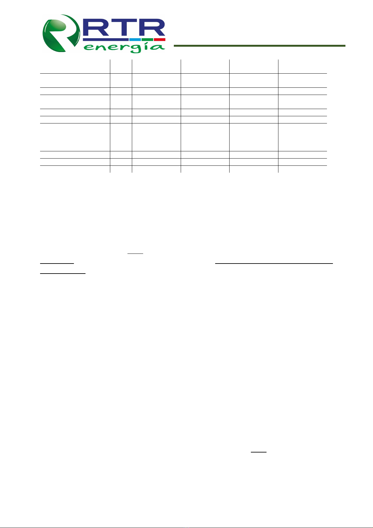
Table 2.1: Technical specifications for 12kVAr, 25kVAr, 50kVAr, and 80kVAr
Parameter Units 12kVAr 25kVAr 50kVAr 80kVAr
Nominal Voltage V 00 ±%1 00 ±%1 00 ±%1 00 ±%1
Maximum Blocking Voltage V 1600 1600 1600 1600
Maximum Operating
Current A 20 0 80 115
Maximum di/dt A/µs 50 100 1 0 1 0
Conductor Cross Section mm
2
16 16 35 35
Number of Semicoductor
Modules - 2 2 2 2
Auxiliary Supply Voltage V - - 230±%10 230±%10
Fan Power Rating VA - - 32 32

TECHNICAL USER´S MANUAL
Thyristor modules
Auxiliary Supply Conductor
Cross Section mm
2
- - 2.5 2.5
Fan Activation
Temperature ºC - - 50 50
Triggering Voltage/Current V/mA 2 /10 2 /10 2 /10 2 /10
Triggering Conductor Cross
Section mm
2
2.5 2.5 2.5 2.5
Overheating Protection ºC 90±5 90±5 90±5 90±5
IP Class - 20 20 20 20
Ambient Temperature
-Operating (Full Load)
-Operating (%75 Load)
-Storage
ºC
ºC
ºC
-20~ 5
-20~60
- 0~100
-20~ 5
-20~60
- 0~100
-20~ 5
-20~60
- 0~100
-20~ 5
-20~60
- 0~100
Relative Humidity % 5~95 5~95 5~95 5~95
Size (W x D x H) mm 158x15 x115 158x15 x115 161x229x197.5 161x229x197.5
Weight kg / lb 2.2 / .9 2.2 / .9 5.9 / 13.0 5.9 / 13.0
3 – Set p
3.1 Prereq isites for Set p
Modules should be mounted on the mounting plate through the mounting holes provided
on the enclosure. Mod les m st be mo nted vertically! A minim m of 150mm clearance is
imperative above and below to dissipate heat efficiently! Do not drill additional mo nting holes
on the device! Modules should be grounded through the mounting holes. 50kVAr and 80kVAr
modules may also be grounded through connecting the ground cable to the auxiliary power
supply connector.
Electrical connections should follow the wiring diagrams provided in Figures 3.3-3.6 in the
Wiring Diagrams section. “S perfast” electronic branch f ses m st be sed to protect the
thyristor mod les!
12kVAr and 25kVAr modules do not require an auxiliary voltage connection. These modules
are powered internally. The 50kVAr and 80kVAr modules are equipped with a fan and are
designed for forced cooling. Therefore, 50kVAr and 80kVAr mod les req ire an a xiliary voltage
(220V 50Hz) s pply to power internal circ its and the cooling fan!
Modules can be instantaneously activated through a power factor correction relay, or any
other compatible system, by applying a 10-2 VDC trigger signal. Internal circuits are galvanically
isolated from the trigger signal.
Thyristor modules are equipped with an external thermostat terminal. If a detuned filter
reactor is used in the system, the user may attach its thermostat to the external thermostat
terminal on the module. This allows the module to protect the detuned filter reactor from
overheating. If this external thermostat connection is not sed, ser m st short the thermostat
connection terminals for the system to f nction properly!

TECHNICAL USER´S MANUAL
5
Thyristor modules
3.2 Installation
CAPACITOR AND DISCHARGE MECHANISM: The recommended capacitor voltages for a 00V
PFC system with and without a detuned filter reactor are listed in Table 3.1. A suitable detuned
filter reactor is recommended to avoid the risk of resonance and reactor acoustic noise.
Table 3.1: Capacitor voltages for PFC with and without a detuned filter reactor
PFC type Recommended Capacitor
Voltage Rating (V)
No detuned filter reactor 00
7% 0
1 % 80
Switching action takes place within 10ms upon receiving the 2 VDC trigger signal given that
the capacitors were appropriately discharged. If the capacitors remain charged, switching action
might be delayed. In point welding and similar applications where capacitors are required to be
switched on and off frequently, the capacitors must be equipped with a discharging. High power
resistors or discharge reactors are recommended to increase switching speed and frequency.
Discharge resistors need to be selected carefully to achieve desired discharge rate. Figures
3.1 and 3.2 show the relationship between the discharge resistance and discharge time for
12.5kVAr, 25kVAr, 50kVAr and 80kVAr PFC systems employing two and three discharge resistors,
respectively. The discharge rates are almost identical for systems with a 7% detuned filter reactor
and without a detuned filter reactor. If a detuned filter reactor is not used, the discharge may be
obtained from 7% curves on Figures 3.1 and 3.2.
The recommended power ratings for common discharge resistor values are listed in Table
3.2. These power ratings allow for safety margins. Avoid use of power resistors lower than the
given ratings. Avoid thermal coupling between the modules and power resistors by keeping a
clearance distance of 150 mm in all directions. Do not place discharge resistors directly
nderneath the mod les!

TECHNICAL USER´S MANUAL
6
Thyristor modules
Fig re 3.1: The effect of discharge resistance on discharge time for 7% (189Hz) and 1 %
(13 Hz) detuned reactor PFC with three discharge resistors. 7% rates may be used if no reactor
is employed.

TECHNICAL USER´S MANUAL
7
Thyristor modules
Fig re 3.2: The effect of discharge resistance on discharge time for 7% (189Hz) and 1 %
(13 Hz) detuned reactor PFC with two discharge resistors. 7% rates may be used if no reactor
is employed.
Table 3.2: Recommended power ratings for discharge resistors
Resistance (kΩ) Resistor Power (W)
5.6 100
10 50
18 25
22 25
39 10
56 10
69 5
SUPERFAST FUSE SELECTION: Each thyristor module should be connected to the line through a
“superfast” branch fuse. Depending on the module type, recommended fuse current and voltage
ratings are listed in Table 3.3.
Table 3.3: “Superfast” fuse ratings for each thyristor module
Model C rrent (A) Voltage (V) Power (kVAr)
12kVAr 35 NH AC 690 12.5
25kVAr 63 NH AC 690 25
50kVAr 125 NH AC 690 50
80kVAr 200 NH AC 690 80
MITIGATING HIGH di/dt: When the thyristors are triggered, the current is initiated at the gate-
cathode junction. The current spreads to the entire junction area as it increases. If the current
time rate of change (di/dt) during this process is faster than the charge carriers in the junction,
then the thyristor may get damaged. Absolute maximum di/dt ratings for thyristor modules are
presented in Table 3. . If these values are exceeded, the thyristor modules might be permanently
damaged. Detuned filter reactors limit the di/dt. If a detuned filter reactor is not used, then a
current limiting reactor with a minimum of 20µH inductance is recommended to protect the
module and maintain a long life expectancy.
Table 3.4: Absolute maximum di/dt ratings for module types
Model di/dt (A/µs)
12kVAr 50
25kVAr 100
50kVAr 1 0
80kVAr 1 0

TECHNICAL USER´S MANUAL
8
Thyristor modules
3.3 Wiring Diagrams
Wiring diagrams with or without detuned filter reactors for 12kVAr, 25kVAr, 50kVAr and
80kVAr modules are presented in Figures 3.3-3.6.
Fig re 3.3: Recommended wiring diagram for 12kVAr and 25kVAr modules with a detuned
filter reactor and a discharge reactor. Connection terminals, wiring diagrams and structures
of 12kVAr and 25kVAr modules are identical.

TECHNICAL USER´S MANUAL
9
Thyristor modules
Fig re 3.4: Recommended wiring diagram for 12kVAr and 25kVAr modules without a detuned
filter reactor and with a discharge reactor. Connection terminals, wiring diagrams and
structures of 12kVAr and 25kVAr modules are identical.

TECHNICAL USER´S MANUAL
10
Thyristor modules
Fig re 3.5: Recommended wiring diagram for 50kVAr and 80kVAr modules with a detuned
filter reactor and a discharge reactor. Connection terminals, wiring diagrams and structures of
50kVAr and 80kVAr modules are identical.

TECHNICAL USER´S MANUAL
11
Thyristor modules
Fig re 3.6: Recommended wiring diagram for 50kVAr and 80kVAr modules without a
detuned filter reactor and with a discharge reactor. Connection terminals, wiring diagrams
and structures of 50kVAr and 80kVAr modules are identical.

TECHNICAL USER´S MANUAL
12
Thyristor modules
3.4 Ready for Start-Up
Module is ready to start up as soon as power and capacitor connections on L1-C1 and L3-C3
terminals are completed. When the module is turned on (including the auxiliary supply voltage
for 50kVAr and 80kVAr), it will be waiting for a trigger signal. As soon as a trigger signal is
detected, the green status LED will light up indicating that the thyristors are triggered and the
capacitors are switched on. The module is equipped with fault detection and a respective LED.
Each is described in the following section.
3.5 Alarms and Indicators
Thyristor modules have four LEDs on the front panel dedicated for alarms, status feedback
and faults. The function of each LED is described as follows:
POWER LED (red): Informs the user that the module is powered up.
FAULT LED (red): Informs the user of internal faults. If the module detects a misconnection on
L1-C1 or L3-C3 terminals, a fault on the discharge mechanism or any other error which must be
cleared before the system is enabled, this LED blinks until the fault is cleared. In case of
overheating, this LED will light up and stay lit until the modules are cooled below 70ºC.
REACTOR FAULT DETECTION LED (red): This LED will light if reactor overheats.
STATUS LED (green): Informs the user that the modules are activated and capacitors are switched
on.
4 – Technical Drawings
Technical drawings for 12kVAr, 25kVAr, 50kVAr and 80kVAr modules are presented in this
section. The frames and dimensions of 12kVAr and 25kVAr are identical. Similarly, frames and
dimensions of 50kVAr and 80kVAr are identical as well.

TECHNICAL USER´S MANUAL
13
Thyristor modules
Fig re 4.1: 12kVAr and 25kVAr modules technical drawings

TECHNICAL USER´S MANUAL
1
Thyristor modules
Fig re 4.2: 50kVAr and 80kVAr modules technical drawings

TECHNICAL USER´S MANUAL
15
Thyristor modules
5 – Tro bleshooting
As explained in Section 3.5, thyristor modules inform the user of various faults and errors
through the four LED indicators on the front panel. The troubleshooting procedures for various
faults and alarms described as follows.
•Power is connected but POWER LED does not light up:
Please check the power connections and the STATUS and/or FAULT LEDs. If none of the
LEDs is lit, then the internal circuitry is not powered. Make sure that power cables, superfast
fuses and switches are all properly wired and power is received by the module.
If any one of the STATUS or FAULT LEDs is lit, then the module is damaged and user should
contact the technical service department at the number provided in Section 7.
•REACTOR FAULT DETECT ON LED is lit:
Please check if the detuned filter reactor thermostat is connected to EXT+ and EXT-
terminals. If a detuned reactor does not exist in the electrical system, then these terminals
must be shorted. They must also be shorted if a detuned filter reactor is used without wiring
the thermostat connections. Otherwise, the module will evaluate this situation as a reactor-
thermal fault and will not let the user switch on the capacitors.
•FAULT LED is blinking:
If the module detects a misconnection on the L1-C1 and L3-C3 terminals, a fault on the
discharge mechanism or any other error which must be cleared before the system is
activated, this LED blinks continuously and prevents the system from activating until the fault
is cleared.
1. Make sure that L1 and L3 are connected to the line through the superfast fuses. If the
connections are correct, then check to see if the fuses are blown.
2. If L1 and L3 are properly connected and the fuses are not blown, then check to see if
C1 and C3 are properly connected to the capacitors.
3. If C1 and C3 are properly connected to the capacitors, then check to see if the
discharge reactors or resistors are damaged, shorted or open-circuited.
4. If the discharge mechanism is damaged, please replace the discharge mechanism and
power up the modules.
5. If a discharge reactor or a discharge resistor is not utilized, the capacitors will stay
charged and the modules will not be able to switch capacitors. Capacitors m st be
eq ipped with a proper discharging mechanism!

TECHNICAL USER´S MANUAL
16
Thyristor modules
•FAULT LED is lit:
The module is in over-heating protection mode. Thermal protection is activated when the
hottest spot of the heat sink is above 90±5ºC. The over-heating fault will not reset until the
hot spot temperature is below 70±5ºC. Make s re the mod les are properly cooled.
1. Make sure the 12kVAr and 25kVAr modules are vertically mounted on the
mounting plates. If the modules are not mounted vertically, they m st not be
powered p!
2. If vertical mounting for 50kVAr and 80kVAr modules is not possible, then user
needs to ensure that cooling air is circulating properly and warm air is removed
from the panel. If the cooling fan is not activated while in over-heating status, then
please check the auxiliary power connections and make sure the module is
powered up properly. If the modules are powered up properly, then please
contact the technical service number provided in Section 7.
•The module is triggered but the STATUS LED is not lit:
STATUS LED displays operating status of the module. If this LED is not lit up, then one of
the following four situations must be true:
1. System is not powered up
2. Trigger signal is not being received
3. Capacitors are charged but not discharging properly
4. System has a wiring error or is in overheating fault mode
First, make sure that the trigger signal is received by the module. To achieve this,
disconnect the REACTOR FAULT DETECTION connections and check to see if the REACTOR
FAULT DETECTION LED lights up when the trigger signal is applied. If the LED lights up, then
the trigger signal is properly received. Then reconnect the REACTOR FAULT DETECTION
connections. If the REACTOR FAULT DETECTION LED is lit, then the system is in reactor
overheating fault protection mode. If the FAULT LED is lit, then the module is in overheating
protection mode and user must wait until the temperature is below 70°C and take
precautions to improve the cooling efficiency. If the FAULT LED is blinking, then please refer
to the related topic under this section. If the POWER LED is on, but the FAULT and REACTOR
FAULT DETECTION LEDs are off, then please contact the technical service department at the
number in Section 7.

TECHNICAL USER´S MANUAL
17
Thyristor modules
6 – Warranty, Terms and Conditions
These modules are warranted against manufacturing defects for 1 (one) year. The modules
are out of warranty in case of user error, use not in accordance with recommended practice
presented in this manual, internal circuits are tampered with and/or the cover is removed.
The manufacturer is not responsible for:
•Any costs resulting from a failure if the installation, setup, repair, alteration, or ambient
conditions of the module do not follow the requirements specified in the documentation
delivered with the module and other relevant documentation.
•Modules subjected to misuse, negligence, or accident.
In no event shall the manufacturer, its suppliers or subcontractors be liable for special,
indirect, incidental, or consequential damages, losses or penalties. If you have any questions
concerning your thyristor modules, please contact the local distributor or RTR Energía. The
technical data, information and specifications are valid at the time of printing. The manufacturer
reserves the right to make modifications without prior notice.
7 – Contact Information
RTR Energía, S.L.
Address: C/ Gavilanes, 11Bis
Pol. Ind. Pinto – Estación
28320 pinto (Madrid) – SPAIN
Phone: +3 916 916 612
Fax: +3 916 912 257
E-mail: [email protected]
Web: www.rtr.es
This manual suits for next models
3
Table of contents