Fleck 2850 Control Valve
Service Manual
16510 Rev J JA11
TABLE OF CONTENTS
JOB SPECIFICATION SHEET ...............................................1
INSTALLATION ......................................................................2
START-UP INSTRUCTIONS ..................................................2
3200 TIMER SETTING PROCEDURE...................................3
3210 TIMER SETTING PROCEDURE...................................4
3200, 3210, 3220, 3230 REGENERATION
CYCLE SETTING PROCEDURE...........................................5
3200 TIME CLOCK TIMER ASSEMBLY.................................6
3210 METER DELAYED TIMER ASSEMBLY ........................7
3220 METER IMMEDIATE TIMER ASSEMBLY .....................8
3230 REMOTE START TIMER ASSEMBLY...........................9
CONTROL VALVE WITH 1700 INJECTOR ASSEMBLY........10
ENVIRONMENTAL POWERHEAD ASSEMBLY ....................11
MANUAL POWERHEAD ASSEMBLY ....................................12
1600 SERIES BRINE SYSTEM..............................................13
1650 BRINE SYSTEM ASSEMBLY........................................14
1700 BRINE SYSTEM ASSEMBLY........................................15
1710 BRINE SYSTEM ASSEMBLY........................................16
1600 SERVICE VALVE OPERATOR ASSEMBLY
(OLD STYLE) .........................................................................17
1" METER ASSEMBLY...........................................................18
1-1/2" METER ASSEMBLY ....................................................19
SAFETY BRINE VALVE 2300.................................................20
2310 SAFETY BRINE VALVE.................................................21
2350 SAFETY BRINE VALVE.................................................22
SEAL & SPACER TOOLS & REPLACEMENT .......................23
GENERAL SERVICE HINTS FOR METER CONTROL .........24
TROUBLESHOOTING ...........................................................25
WATER CONDITIONER FLOW DIAGRAMS .........................26
FLOW DATA & INJECTOR DRAW RATES ............................27
DIMENSIONS.........................................................................28
SYSTEM #4 ...........................................................................29
SYSTEM #5 INTERLOCK .....................................................29
SYSTEM #6 ...........................................................................30
SYSTEM #7............................................................................30
SYSTEM #4 WIRING .............................................................31
SYSTEM #5 WIRING .............................................................33
SYSTEM #6 WIRING .............................................................34
SYSTEM #7 WIRING .............................................................35
SERVICE ASSEMBLIES ........................................................36
JOB SPECIFICATION SHEET
Job Number: ___________________________________________________
Model Number: _________________________________________________
Water Hardness: _______________________________________ ppm or gpg
Capacity Per Unit: _______________________________________________
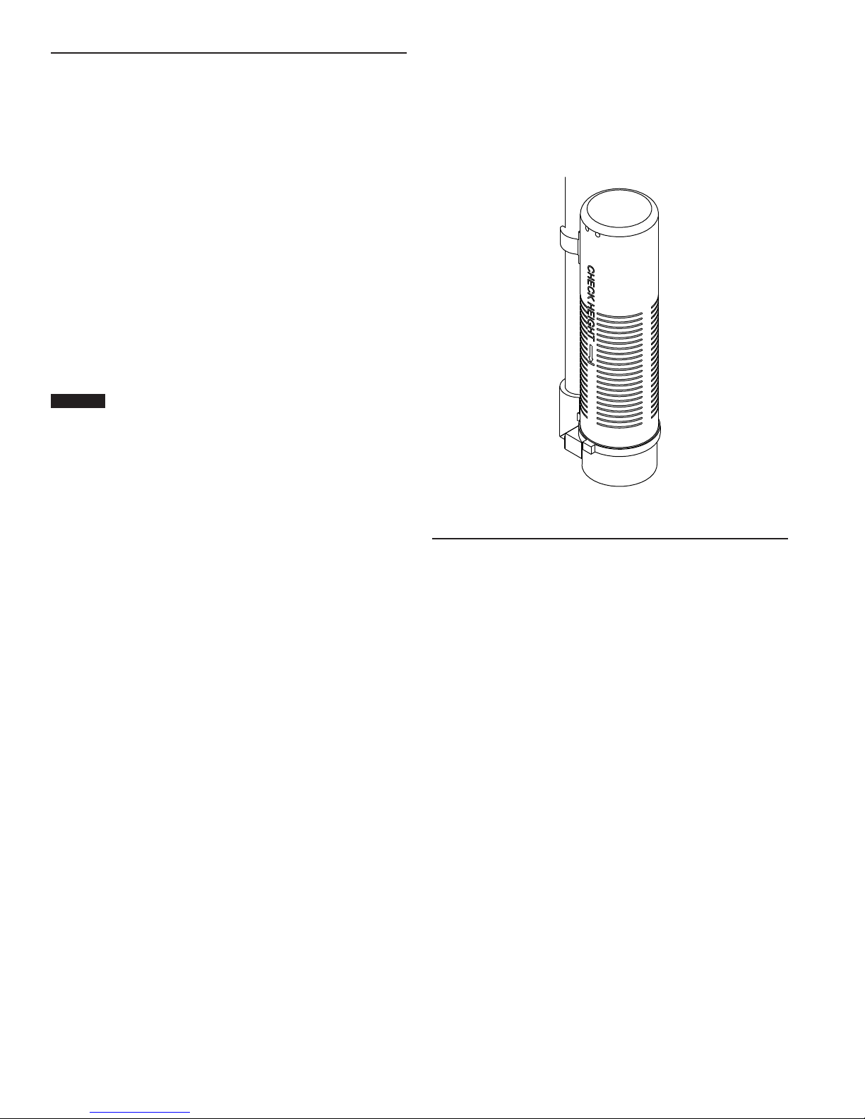
Mineral Tank Size: ______________ Diameter: ________ Height: _________
Salt Setting per Regeneration: _____________________________________
1. Type of Timer:
A. 7 Day or 12 Day
B. Meter Initiated
2. Downow: Upow UpowVariable
3. Meter Size:
A. 3/4" Std Range (125 - 2,100 gallon setting)
B. 3/4" Ext Range (625 - 10,625 gallon setting)
C. 1" Std Range (310 - 5,270 gallon setting)
D. 1" Ext Range (1,150 - 26,350 gallon setting)
E. 1-1/2" Std Range (625 - 10,625 gallon setting)
F. 1-1/2" Ext Range (3,125 - 53,125 gallon setting)
G. 2" Std Range (1,250 - 21,250 gallon setting)
H. 2" Ext Range (6,250 - 106,250 gallon setting)
I. 3" Std Range (3,750 - 63,750 gallon setting)
J. 3" Ext Range (18,750 - 318,750 gallon setting)
K. Electronic_________ Pulse Count ________ Meter Size _______
4. System Type:
A. System #4: 1 Tank, 1 Meter, Immediate, or Delayed Regeneration
B. System #4: Time Clock
C. System #4: Twin Tank
D. System #5: 2-5 Tanks, Interlock Mechanical
2-4 Tanks, Interlock Electronic
Meter per unit for Mechanical and Electronic
E. System #6: 2-5 Tanks, 1 Meter, Series Regeneration, Mechanical
2-4 Tanks, 1 Meter, Series Regeneration, Electronic
F. System #7: 2-5 Tanks, 1 Meter, Alternating Regeneration,
Mechanical
2 Tanks only, 1 Meter, Alternating Regeneration,
Electronic
G. System #9: Electronic Only, 2-4 Tanks, Meter per Valve, Alternating
H. System #14: Electronic Only, 2-4 Tanks, Meter per Valve. Brings
units on and ofine based on ow.
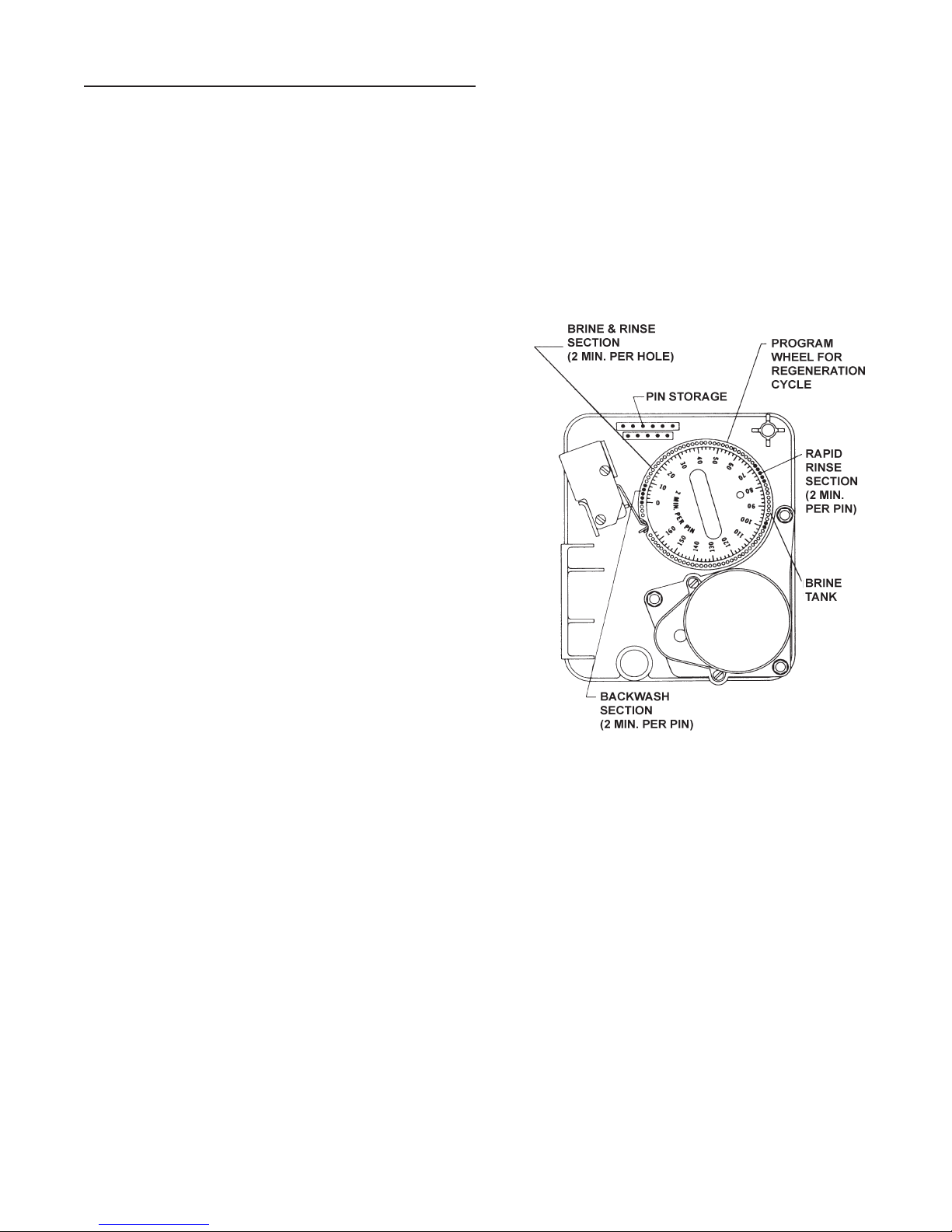
5. Timer Program Settings:
A. Backwash: ___________________________________ Minutes
B. Brine and Slow Rinse: __________________________ Minutes
C. Rapid Rinse: _________________________________ Minutes
D. Brine Tank Rell: ______________________________ Minutes
E. Pause Time:__________________________________ Minutes
F. Second Backwash: ____________________________ Minutes
6. Drain Line Flow Control: ______________________________gpm
7. Brine Line Flow Controller: ____________________________gpm
8. Injector Size#: ____________________________________________
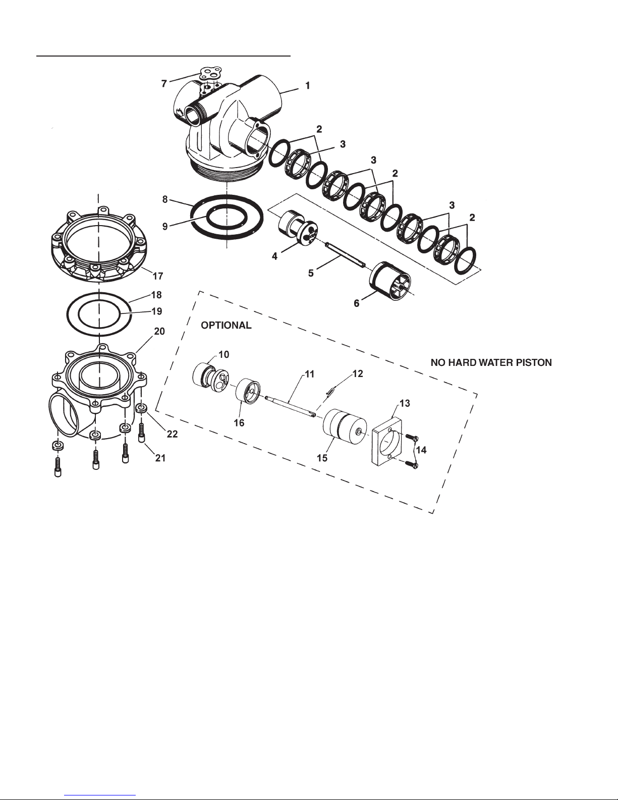
9. Piston Type:
A. Hard Water Bypass
B. No Hard Water Bypass