Teledyne CombiFlash Torrent User manual

CombiFlash Torrent®
Installation Guide 69-5243-110
Released June 2, 2020
1.1 Documentation Overview
This Installation Guide provides:
• Safety Information
• Unpacking instructions
• Installation instructions, including placing the CombiFlash Torrent module
on a network and direct connections with a computer or hand-held device
• Certification and warranty information.
Once you are operating the Torrent, you may refer to the Help menu for operating
instructions and further assistance.
WARNING
Avoid hazardous practices! If you use this instrument in any way not specified in
this manual, the protection provided by the instrument may be impaired; this may
increase your risk of injury.
1.2 Product Overview
The Teledyne Isco CombiFlash Torrent and Torrent AQ flash chromatography
systems give you high-productivity automation, programmable gradients, UV or
UV-Vis detection and peak separation, and automatic detection of columns.
The Torrent can separate a sample in an unattended run under computer control
at user selected flow rates between 50 and 1000 mL/min. The Torrent operates up
to 100 psi (6.9 bar) and can use low- or medium-pressure Flash columns for either
normal or reversed phase separations.
Braided stainless steel 2.75 meter (9 foot) supply lines are supplied with the
Torrent. These supply lines support the solvent level detection features that
prevent chromatography runs from running out of solvent.
Samples can be introduced to the Torrent by injecting a liquid sample into the
injection port. Liquid samples can also be pumped into the injection port using the
optional Sample Load Pump. Alternately, liquid samples can automatically be
loaded on the Torrent AQ using the integrated sample load line on the solvent
select valve. The Torrent can load low-solubility and liquid samples using solid
load sample cartridges.
Column eluate passes through the UV or UV-Vis detector which can trigger
collection of peak fluids. The system also accepts an input signal to cut peaks
using an external detector such as an ELSD instrument.
The Torrent can control a Foxy R2 High Flow fraction collector or a Fractionation
Valve to isolate the fluid in vessels.

CombiFlash Torrent Installation Guide
1.3 Specifications
1.4 Safety
Before installing, operating, or maintaining this equipment, it is imperative that
all hazards and preventive measures are fully understood. While specific hazards
may vary according to location and application, take heed in the following general
warnings:
Table 1-1 CombiFlash Torrent Module Specifications1
Sample size: 0.5 to 300 grams
RediSep Rf column
sizes:
80 gram to 3 kilogram
Flow rate: 50 – 1000 mL/min
Maximum pressure2: 6.89 bar (100 psi)
Detection: 200 – 400 nm (200 – 800 nm optional) with single,
dual, or All-wavelength Collection.
Accepts external detector input.
Gradient: Binary, high pressure solvent mixing with linear, step,
or isocratic capability. Two solvent inlets.
Gradient accuracy: <2% full scale from 0.2 to 1.0 liter/min.
Sample injection: Automated injection with options of solid load
cartridges, liquid load, or direct injection.
Controller: 26.7 cm (10.4 inch) touch screen
Supports remote control via Windows® PC.
Software: On-screen method development and control with
PeakTrak software
Fraction collection: Up to four fraction collectors, fractionation valve, or
manual collection
Solvent management: Patented, active level sensing for inlet and waste
containers
Module dimensions:
(W x D x H)
47 x 43.5 x 71.4 cm
18.5 x 17.9 x 28.1 inches
Module weight: 65 lbs (29.5 kg)
Operating voltage: 100 VAC 50 Hz, 2 amperes
117 VAC 60 Hz, 2 amperes
234 VAC 50 Hz, 1 ampere
(±10% of the region’s nominal line voltage)
Safety and sample
security:
Static-dissipative tubing throughout,
Vapor sensor for internal leak detection,
Overpressure sensor,
Active solvent and waste level sensing,
Audible alarm when user intervention is required.
Ambient Temperature 20 to 40°C (maximum temperature must be at least
15°C below the boiling point of the solvent)
Humidity (when
connected to power)
95% relative humidity maximum at 20 to 40°C
Certification: CE
Electrical Safety per EN 61010-1
Installation Category II
Maximum Altitude 2000 meters
Pollution Degree 2
Note 1. All specifications are subject to change.
Note 2. For columns undetected by RFID, the max pressure is limited to 50 psi.

Section 1 Introduction
WARNING
Avoid hazardous practices! If you use this instrument in any way not specified in
this manual, the protection provided by the instrument may be impaired.Liquids
associated with this instrument may be classified as carcinogenic, biohazard,
flammable, or radioactive. Should these liquids be used, it is highly recommended
that this application be accomplished in an isolated environment designed for
these types of materials in accordance with federal, state, and local regulatory
laws, and in compliance with your company’s chemical/hygiene plan in the event
of a spill.
WARNING
If you are using flammable solvents or chemicals with this system, vapor
concentration levels may exceed the maximum exposure levels as recommended
by OSHA Guide 1910.1000. To reduce those levels to a safe exposure, Teledyne
Isco recommends that you place the system in a laboratory hood designed for the
purpose of ventilation. This hood should be constructed and operated in
accordance with federal state and local regulations. In the event of a solvent or
chemical spill, your organization should have a plan to deal with these mishaps.
In all cases, use good laboratory practices and standard safety procedures.
WARNING
The CombiFlash Torrent has redundant safety devices to limit pressure to less
than 100 psi (689 kPa). RediSep columns smaller than 100 g are CE certified using
standard IEC61010-1 for use on the CombiFlash Torrent. RediSep columns larger
than 100 g meet Pressure Vessel Directive 97/23/EC. Teledyne Isco strongly
recommends against the use of columns rated less than 100 psi (689 kPa).
1.4.1 Hazard Severity Levels
This manual applies Hazard Severity Levels to the safety alerts. These three
levels are described in the sample alerts below.
CAUTION
Cautions identify a potential hazard, which if not avoided, may result in minor or
moderate injury. This category can also warn you of unsafe practices, or conditions
that may cause property damage.
WARNING
Warnings identify a potentially hazardous condition, which if not avoided, could
result in death or serious injury.
DANGER
DANGER – limited to the most extreme situations to identify an imminent
hazard, which if not avoided, will result in death or serious injury.

CombiFlash Torrent Installation Guide
1.4.2 Hazard Symbols
The equipment and this manual use symbols used to warn of hazards. The
symbols are explained in Table 1-2.
Table 1-2 Hazard Symbols
Warnings and Cautions
The exclamation point within the triangle is a warning
sign alerting you of important instructions in the
instrument’s technical reference manual.
The lightning flash and arrowhead within the triangle is a
warning sign alerting you of “dangerous voltage” inside
the product.
The pinch point symbol warns you that your fingers or
hands will be seriously injured if you place them
between the moving parts of the mechanism near these
symbols.
Symboles de sécurité
Ce symbole signale l’existence d’instructions
importantes relatives au produit dans ce manuel.
Ce symbole signale la présence d’un danger
d’électrocution.
Risque de pincement. Ces symboles vous avertit que
les mains ou les doigts seront blessés sérieusement si
vous les mettez entre les éléments en mouvement du
mécanisme près de ces symboles
Warnungen und Vorsichtshinweise
Das Ausrufezeichen in Dreieck ist ein Warnzeichen, das
Sie darauf aufmerksam macht, daß wichtige
Anleitungen zu diesem Handbuch gehören.
Der gepfeilte Blitz im Dreieck ist ein Warnzeichen, das
Sei vor “gefährlichen Spannungen” im Inneren des
Produkts warnt.
Vorsicht Quetschgefahr! Dieses Symbol warnt vor einer
unmittelbar drohenden Verletzungsgefahr für Finger und
Hände, wenn diese zwischen die beweglichen Teile des
gekennzeichneten Gerätes geraten.

Section 1 Introduction
1.5 For Additional Information
Technical assistance for the Torrent can be obtained from:
Teledyne Isco
4700 Superior St.
Lincoln NE 68504
Phone: (800) 228-4373 or (402) 464-0231
Fax: (402) 465-3001
E-mail: [email protected]
Advertencias y Precauciones
Esta señal le advierte sobre la importancia de las
instrucciones del manual que acompañan a este
producto.
Esta señal alerta sobre la presencia de alto voltaje en el
interior del producto.
Punto del machacamiento. Sus dedos o manos seriusly
serán dañados si usted los coloca entre las piezas
móviles cerca de estos símbolos.
Table 1-2 Hazard Symbols (Continued)

CombiFlash Torrent Installation Guide

CombiFlash To r re n t ®
Installation Guide
Section 2 Preparation
This section provides instructions for unpacking and installing the CombiFlash Torrent
system. To prepare the system for operation, sequentially follow all instructions in
sections 2.1 through 2.18. Some of these sections provide instructions for installing
optional equipment which should only be completed as required.
Note
Section 2.20 contains an Installation Qualification checklist. If required, sign off the
checklist entries as you successfully complete the following sections.
2.1 Optional Equipment Modules
The Torrent/Torrent AQ offer several different optional modules. Each module will
require additional set-up steps as noted below. The optional modules are:
1. Solvent Selection Valve (Sections 2.4.1; 2.6.2 and 2.8)
2. Sample Load Pump (Sections 2.6.1 and 2.12.1)
3. Fractionation Valve (Sections 2.4.2; 2.6.3 and 2.12.3)
4. Foxy R2 High Flow Fraction Collector (Sections 2.6.4; 2.12.2 and/or 2.17)
2.2 Unpacking the Unit
The Torrent is shipped in a single carton. The optional equipment will be shipped in
additional cartons. Carefully unpack the shipment and inspect the contents.
WARNING
The Torrent is heavy. Use a two-person lift to prevent injury.
Lift the Torrent from the container using the lifting handles mounted on the
side panels.
If there is damage to the shipping carton or any components, contact the
shipping agent and Teledyne Isco (or its authorized representative)
immediately.
WARNING
If there is any evidence that the Torrent has been damaged in shipping, do not plug it
into AC power. Contact Teledyne Isco or its authorized representative for advice.
Compare the contents of the boxes with the enclosed packing slips. If there are any
shortages, contact Teledyne Isco immediately.
2.3 Instrument Location
The Torrent has a relatively small footprint for a development-scale instrument,
requiring about 2200 square centimeters (350 in2) of level bench space. Ensure that the
Torrent has at least 3 cm (1.25") of air space behind it for ventilation. Additional space
may be required for solvent and waste containers, and fraction collection.
Refer to Table 1-1 for environmental conditions and power requirements.

CombiFlash Torrent Installation Guide
WARNING
The system is heavy. Use a two-person lift to prevent injury.
Before making any connections to the Torrent, place it on the bench or in the fume hood
where it will be operated. Temporarily position the Torrent so you can access the back panel
to complete the connections.
2.4 Mounting Optional Modules
If a Solvent Select Valve or Fractionation valve are not being
installed you can skip this section and continue to Section 2.5.
2.4.1 Solvent Select Valve (if purchased)
Place the Solvent Select Valve on the left-hand side of the Torrent
with the valve facing the side of the Torrent.
Use the supplied metal mounting plate and four (4) screws to
secure the Solvent Select Valve to the Torrent.
2.4.2 Fractionation Valve (if purchased)
Place the Fractionation Valve on the right-hand side of the Torrent
with the Valve facing the side of the Torrent.
Use the supplied metal mounting plate and four (4) screws to
secure the Fractionation Valve to the Torrent.
Alternatively, the valve can be connected to a user supplied mast.
2.5 Connect Power
Ensure that the On/Standby switch above the touch screen panel is in the Standby position.
Then, use the supplied IEC power cord to connect the Torrent to mains power.
WARNING
Mains power must meet the voltage, frequency, and amperage requirements listed on the
serial number label. Input voltage must be within ±10% of the region’s nominal line voltage.
In the USA, this is 117 volts ±11.7 volts.
WARNING
As long as the AC mains power cord is connected to a live outlet, power is inside the unit.
The mains power cord is the disconnect device. Position the Torrent so that the power cord
can be unplugged, or use a power strip where the plug can quickly be removed from the
outlet in the event of an emergency.
CAUTION
Unless power must be removed due to an emergency, always wait at least one minute after
placing the system in Standby before removing the AC mains power cord.
2.6 Connect Interface Cables
Rear panel connections support a variety of devices. Electrical connections to networks or
optional equipment should be completed at this time.
Review the options below and complete as necessary. If any optional modules are not being
installed you can continue to Section 2.7.

Section 2 Preparation
Note
Detailed information about each of these optional devices is provided in Section 2.12
Plumbing Optional Modules To Torrent.
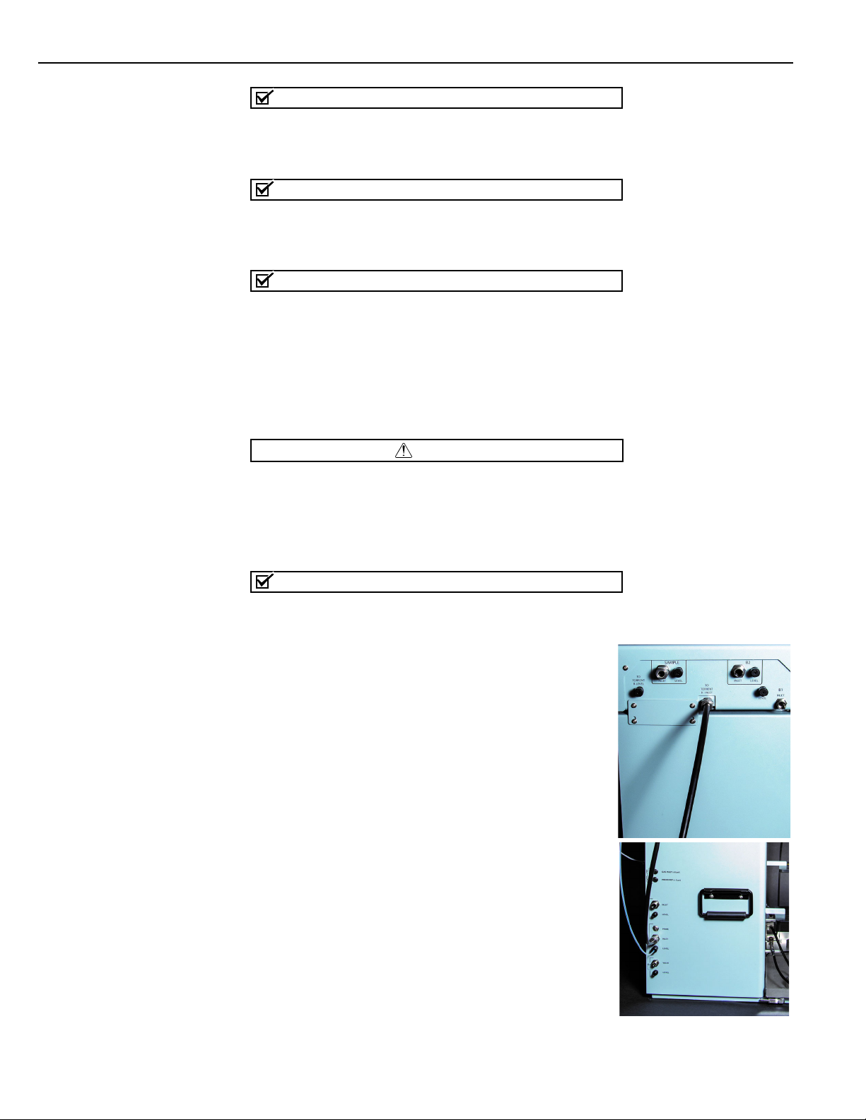
2.6.1 Cabling: Sample Load Pump
To connect a Sample Load Pump to the Torrent, attach the pump’s power cable to the
Torrent’s back panel connector labeled “SAMPLE LOAD PUMP.”
2.6.2 Cabling: Solvent Select Valve
To connect a Solvent Select Valve to the Torrent,
attach the valves power cable to the back panel
connector labeled “SAMPLE LOAD PUMP” and
connect the USB cable to the USB port on the back
panel.
2.6.3 Cabling: Fractionation Valve
To connect a Fractionation Valve to the Torrent,
attach the valve’s 9-pin power/control cable between
the port on the back of the Fractionation Valve to
the Torrent’s back panel connector labeled
“FRACTION VALVE.”
2.6.4 Cabling: Foxy R2 High Flow Fraction Collector
The Torrent can control up to four Foxy R2 High Flow fraction collectors via an
Ethernet network.
To connect one, or the first of multiple Foxys,
connect a standard straight-through network cable
between the Ethernet ports on the Torrent and a
Foxy. The second Ethernet port on the Foxy can be
used to add the next Foxy. See section 2.11.2 for
more details.
The Torrent can supply AC power to one Foxy.
Connect one end of the cable to the female IEC
connector on the Torrent. Connect the other end to
the Foxy power connector.
2.6.5 Cabling: Network Connection
The Torrent can be added to a network or directly
connected to a computer for remote control.
To add the Torrent to a network, connect a standard
straight-through network cable between the
Torrent’s Ethernet port and your network.
To connect the Torrent directly to a computer,
connect a “crossover” cable between the Ethernet
ports on the Torrent and a stand-alone computer.
To connect to a network, you will need access to IP
addresses and network information from your IT
department. For more information on network
guidelines, see TN28 Networking Guidelines for
CombiFlash Products, available at www.isco.com.

CombiFlash Torrent Installation Guide
Note
When using the Foxy R2 High Flow fraction collector, the Torrent’s rear panel Ethernet connector
will be in use. Instead, connect the cable to the available Ethernet port on the last Foxy in the
chain.
Note
The Foxy R2 fraction collector does not support DHCP. If you are adding the Torrent with Foxy R2
fraction collectors to your organization’s network, a static IP address must be assigned to each
unit. Contact your IT department for assistance.
Note
Detailed information about networking the Torrent with one or more Foxys is provided in
Section 2.12.2 OPTIONAL FOXY R2 HIGH FLOW FRACTION COLLECTOR.
2.7 Position the Torrent
After completing the various back panel connections, the Torrent can be moved to its
operating position. Turn the Torrent so that the operator can access all of the front view
features and controls. Use care not to damage the connections, cables and equipment while
moving the Torrent.
CAUTION
Ensure that the CombiFlash Torrent has at least 3 cm (1.25") of air space behind it for ventilation.
Determine where the solvent and waste containers will be located. Keep in mind that the
valve wash waste is located on the Torrent’s left side panel; diverter valve waste will come
from the fraction collector or fractionation valve, usually positioned on the right side of the
Torrent. If these will use a common waste container, determine the preferred location.
Note
A common waste container is recommended for waste level monitoring to prevent overfilling.
2.8 Connect Solvent Select Valve Plumbing
If a Solvent Select Valve is not being installed you can skip
this section and continue to Section 2.9. If a Solvent Select
Valve is to be installed with the Torrent or Torrent AQ it
should already be mounted.
1. Connect the preswaged end of black tubing (023050308)
to Torrent “B INLET”.
2. Loosen (but don’t remove) the nut and 2-piece ferrule
connected to the Solvent Select Valve port “TO TORRENT B
INLET”.
3. Place the free end of the black tubing into the port as far
as it will go and finger tighten the nut. Then use a wrench
to tighten for a n additional 1 and 1/4 turn.
4. a) Locate a nut (60-0923-015) and ferrule (60-0083-163) in
the accessory package (60-5249-002).
b) Insert the ferrule, narrow end first, into the Torrent “B
LEVEL”.
c) Loosely thread the nut onto the “B LEVEL” port.
d) Insert the clear air supply line (supplied with Solvent
Select Valve) into the “B LEVEL” port until it is fully seated.

Section 2 Preparation
e) Finger tighten the nut. If desired, tighten the nut an additional 1/2 turn using a
wrench.
5. Loosen the nut (but do not remove) to the Solvent Select Valve Port “TO TORRENT
B LEVEL”.
6. Following step 4 above, connect the air supply from the B LEVEL on the Torrent to
the Solvent Select Valve “TO TORRENT B LEVEL”.
2.9 Connect Solvent Lines
CAUTION
To prevent damage or premature wear to the pump and internal valves, clean solvent should
be used. The solvent should not contain any dissolved solids. In addition, the B solvent pump
on the Torrent and both Solvent A and Solvent B pumps on the Torrent AQ are not
compatible with alkanes such as hexane due to lack of lubricity.
CAUTION
If solvent containers are reused, particulate matter can accumulate in the container.
Containers should be thoroughly cleaned before each refill. Failure to clean the containers
may result in damage to the solvent selection valve and internal components.
Note
The Torrent is shipped with protective caps on the solvent fittings. Remove these caps as you
connect the solvent lines. The internal solvent lines contain isopropyl alcohol, some of which
may drain when the caps are removed.
The Torrent may receive solvent from:
• User-supplied solvent containers at atmospheric pressure
• Pressurized or gravity-fed solvent delivery lines in the laboratory.
Refer to the appropriate installation section (2.9.1 through 2.9.2) according to your
solvent source.
2.9.1 Solvent Containers at Atmospheric Pressure
The Torrent can form a binary gradient from two solvents, A and B. These solvents
connect to the left side panel of the Torrent or Torrent AQ with optional Solvent Select
Valve allows for a binary gradient between one A solvent and either of two different B
solvents or liquid sample.
1. Locate the Solvent A inlet line. This assembly consists of two tubes fastened
together—a solvent line and a smaller diameter air line to measure the solvent
level.
2. Connect the large fitting to the Torrent’s A INLET port:
a. Position the end with the threaded fitting near the port.
b. Rotate the fitting until the inlet line is routed the desired direction.
c. Finger-tighten the pre-swaged fitting to the port.
d. Use a wrench to tighten the fitting an additional 18turn.
3. Connect the air line to the A LEVEL port (refer to Figure 2-1):
Figure 2-1 Level tubing connection with nut and ferrule
Tubing
Nut
60-0923-015
Ferrule
60-0083-163
Level Port

CombiFlash Torrent Installation Guide
a. Locate a nut (60-0923-015) and ferrule (60-0083-163) in the accessory package
(60-5249-002).
b. Insert the ferrule, narrow end first, into the A LEVEL port.
c. Loosely thread the nut onto the A LEVEL port.
d. Insert the Solvent A air line into the A LEVEL port until it is fully seated.
e. Finger-tighten the nut. If desired, tighten the nut an additional 12turn using a
wrench.
Important
For systems without Solvent Select Valve follow steps 4-7. For systems with Solvent
Select Valve skip to steps 8-14.
4. Locate the Solvent B inlet line. This assembly consists of three tubes fastened
together—a solvent line, a smaller diameter air line, and a solvent prime line.
5. Connect the large fitting on the Solvent B inlet line to the Torrent’s B INLET port as
described in step 2.
6. Connect the smallest tube of the Solvent B inlet line to the B LEVEL port as described
in step 3.
7. Connect the remaining tube of the Solvent B inlet line to the B PRIME port:
a. Finger-tighten the pre-swaged fitting to the port
labeled B PRIME.
b. Use a wrench to tighten the fitting an additional 18
turn.
8. The Solvent Select Valve should be plumbed to the B
Inlet of the Torrent (Section 2.2.6).
9. Locate the Sample Inlet line. This assembly consists of
two tubes fastened together--a white solvent line and a
smaller diameter air line.
10.Connect the large fitting on the Solvent B1 inlet line to
the Solvent Select Valve’s B1 INLET port as described in
step 2 above.
11.Connect the smalled tube of the Solvent B1 inlet line to
the Solvent Select Valve’s B Level port as described in
step 3.
12.Locate the Solvent B1 inlet line. This assembly consists
of two tubes fastened together--a solvent line and a
smaller diameter air line.
13.Connect the large fitting on the Solvent B1 inlet line to
the Solvent Select Valve’s B1 INLET port as described in
step 2 above.
14.Connect the smalled tube of the Solvent B1 inlet line to
the Solvent Select Valve’s B1 inlet line to the Solvent
Select Valve’s B Level port as described in step 3.
15.Locate the Solvent B2 inlet line and repeat Steps 9 and
10 for the B2 inlet line.
The other ends of the Solvent A and B lines should be
placed in the respective solvent containers. If using the
optional Solvent Inlet Cap sets (60-5394-510 for 83B
closures, 60-5394-511 for 100 mm closures), proceed with
the following steps:
16.Screw the cap onto the carboy.

Section 2 Preparation
17.Feed the solvent line assembly through the hole in the cap. The weighted inlet
should rest at the bottom of the container.
2.9.2 Pressurized Solvent Lines in the Laboratory
When receiving solvent from pressurized lines on-site, the Torrent’s solvent level
sensing feature is unsupported (and unnecessary).
Note
The solvent pressure should be regulated to not exceed 5 psi.
To complete the solvent connections:
1. Ensure that the solvent supply lines have shut-off valves. These valves must be
accessible to the user.
Note
The solvent supply should be shut-off when the system is not in use. Otherwise,
pressurized solvent may be forced through the CombiFlash Torrent pump seals and leak
from the waste port or other fluid path from the automated injection valve.
2. Locate the 18-inch plug, part number 209-0165-21, in accessory kit 60-5249-002.
Install this plug on the B Prime port.
3. Connect user-supplied tubing with 38-inch fittings from the source to the A Inlet
and B Inlet ports on the side panel.
Note
Solvent Level Sensing and B Solvent Prime options should be disabled when completing
the system configuration settings in section 2.13.1.
2.10 Connect Waste Lines
WARNING
Risk of fire or equipment damage. Failure to connect Waste Port tubing may allow
organic solvents to pool in unsafe areas, possibly creating dangerous levels of
flammable vapors.
CAUTION
Elevated flammable vapor levels are possible. Ensure that the waste container is
adequately ventilated, preferably by placing it in a fume hood.
Note
The Torrent is shipped with protective caps on the waste fittings. Remove these caps as
you connect the waste lines. The internal solvent lines contain isopropyl alcohol, some of
which may drain when the caps are removed.
Note
Waste connections on the left side panel are labeled with a Waste icon.
The waste tube assembly is a bundle of two tubes that routes post-run
valve wash fluid to a waste container. Instructions for diverter valve waste tubing is
covered in the PLUMBING OPTIONAL MODULES TO TORRENT section (2.12).
To connect the waste tube assembly to the Torrent:

CombiFlash Torrent Installation Guide
1. Select the tube with the pre-swaged nut and ferrule and connect this end to the port
labeled VALVE. The connection should be finger-tight. Then, use a wrench to tighten
the fitting an additional 18turn.
2. Connect the other line to the LEVEL port:
a. Locate a nut (60-0923-015) and ferrule (60-0083-163) in
the accessory package (60-5249-002).
b. Insert the ferrule, narrow end first, into the LEVEL port.
c. Loosely thread the nut onto the LEVEL port.
d. Insert the waste air line into the LEVEL port until it is
fully seated.
e. Finger-tighten the nut. If desired, tighten the nut an
additional 12turn using a wrench.
The other ends of the Waste line should be placed in the waste
container.
If using the optional Waste Outlet Cap (60-5394-512 for 83B closures, 60-5394-513 for 100
mm closures), proceed with the following steps:
3. Place the metal plate inside the plastic cap (Figure 2-2). The plate should be oriented so
that the small tube will extend into the carboy. The small tube should extend 5 ±0.5 cm
long from nut. If the tube is missing, insert it now and finger-tighten the nut.
Figure 2-2 Optional Waste Cap (83B cap shown)
4. The tubing is secured using metal, spring-type retainers. A pair of conventional pliers
will allow you to open the retainer enough to slide it onto the tubing. On the larger
diameter waste tube, slide one retainer about 2 inches (5 cm) onto the tubing end.
5. Feed this tube into the top of the metal plate until the retainer is against the top of the
plate.
6. Slide a retainer onto the tubing end until it is seated against the bottom of the metal
plate.
7. Thread the cap onto the carboy.
8. The smaller diameter tube is the level sense tube. Push this tube about 2 cm into the
top fitting and finger-tighten the nut.
If an optional waste cap is not used, ensure the waste lines are secured so they drain into
the waste container. Secure the Waste Level Sense air tubing so its outlet is at least two
inches (5 cm) below the container’s maximum level. Seal the container opening to avoid
solvent vapors.
Nut
Metal Plate
5 cm tube extending
into carboy
Spring-type
Retainer
Place a retainer above and
below the metal plate.

Section 2 Preparation
2.11 Connect and Route Drain Line
WARNING
Risk of fire or equipment damage. Failure to connect drain lines may allow organic
solvents to pool in unsafe areas, creating a potential for dangerous levels of flammable
vapors. Improper draining may damage the instrument’s internal components.
The Torrent has a front-mounted drip tray. There is a drain connection under the left
side of the tray. Connect user-supplied tubing to this drain and route it to a suitable
waste fluid collection container.
2.12 Plumbing Optional Modules to Torrent
The installation of optional equipment that was electrically connected to the Torrent in
section 2.6 should be completed now. Review the options below and complete as
necessary. If any optional modules are not being installed you can skip this section and
continue to Section 2.13.
2.12.1 Optional Sample Load Pump
1. Position the Sample Load Pump on top or near the
Torrent.
2. Connect the tubing between the pump outlet (from
the bottom of the pump head) and the Torrent’s
sample injection port (Figure 1-1, item 9).
3. Configure the Sample Load Pump by placing either
the plastic cartridge reservoir or the tubing with the
weighted end on the pump inlet (Figure 2-3).
Figure 2-3 Sample load pump
2.12.2 Optional Foxy R2 High Flow Fraction Collector
The fraction collector(s) should be positioned to the right of the Torrent. Complete
information about the Foxy R2 fraction collector is provided in its user manual, part
#69-2133-667.
Pump Outlet
To Sample Injection Port
Cartridge Reservoir
Tubing with
Weighted End Pump Inlet

CombiFlash Torrent Installation Guide
Plumbing Setup:
• Connect the 107 cm (42 inch) piece of supplied tubing
between the Torrent’s TO COLLECTOR port and the
fraction collector’s diverter valve IN port (Common). Use
caution when tightening the hardware to prevent damage
to the diverter valve.
• If there are multiple fraction collectors, connect the 107 cm
(42 inch) piece of supplied tubing between the first fraction
collector’s diverter valve WASTE port (NO) and the next
collector’s diverter valve IN port (Common). Repeat this for
each fraction collector in the chain.
• On the last fraction collector (or single), connect the 6 ft.
piece of supplied tubing between the diverter valve WASTE
port (NO) and a suitable waste collection container. Cut the
tubing to the desired length.
•For waste level monitoring, the valve wash waste container
(section 2.10) is recommended for collecting diverter valve
waste.
• Install racks or funnels as described in the Installation
Guide.
Figure 2-4 Foxy R2 high flow diverter valve ports (front view)
• Use the supplied cable ties to secure the tubing as desired. Before turning on any
fraction collector, manually move each fraction collector’s arm and drop former
through its full range of movement to ensure that the arm mechanisms move freely
without obstruction. The Foxy R2 will need to be configured once the system is
powered on (Section 2.15 or 2.16).
2.12.3 Optional Fractionation Valve
The fractionation valve is an alternative to the typical Foxy
fraction collector setup, allowing the effluent from the Torrent
to be collected in any of six user-supplied containers. The
fractionation valve module includes a diverter valve to allow
the effluent to be diverted to waste.
1. Connect the supplied tubing between the Torrent’s TO
COLLECTOR port and the Fractionation Valve’s diverter
valve IN port (Common). (The diverter valve is an
externally mounted solenoid valve on the side of the
Fractionation Valve.)
2. Connect the supplied tubing between the Fractionation
Valve Common Port to the Fractionation Valve’s diverter
valve top port.
Waste (NO)
In (Common)
Drop Former (NC)

Section 2 Preparation
Figure 2-5 Fractionation valve: Diverter to waste valve connections
3. Cut lengths of tubing and connect the pieces to the six numbered outlet ports on the
front valve (Figure 2-6).
4. For your convenience, the Fractionation Valve was shipped with pairs of numbered
clips to simplify tube and container identification. If desired, attach the clips to the
each end of the six outlet tubes.
5. Secure the six outlet tubing ends in the waste containers.
Note
Tubing may be secured in the collection containers using optional bottle caps with
spring-type retainers. For GL38 threads, use 60-5394-516; for GL45 threads, use
60-5394-517.
6
1
2
5
3
4

CombiFlash Torrent Installation Guide
Figure 2-6 Six-port valve connections
2.13 Model 340CF Evaporative Light Scattering Detector (ELSD)
The Torrent can be configured for use with Teledyne Isco’s 340CF ELSD.
If a 340CF ELSD is no being installed you can skip this section and continue to
Section 2.14. The data connection between the Torrent and the ELSD requires either a
Foxy R2 fraction collector (Section 2.12.2) or the fractionation valve (Section 2.6.3).
Connect the ELSD to the DETECTOR port on the rear panel of the Foxy R2 or the
fractionation valve with signal cable (250000020) from the 340CF Accessory Package
(4-200203).
Note
If your system has more than one fraction collector, connect the ELSD to the first unit plumbed to
the Torrent.
Figure 2-7 Detector port on fractionation valve (left) and Foxy R2 fraction collector (right)
1
2
3
4
5
6
Collection Vessels
From
T
orrent
Normally
Closed
Common
Normally
Open
Waste
From top of diverter valve

Section 2 Preparation
Plumbing the Torrent to the ELSD requires the connection package, part
#60-5247-021. The package contains the following:
• Metal Tee fitting with reducer
• Two 0.25” mounting spacers for tee
• Two #6x1” pan head screws/flat washers/lock washers
• 1 pc 1/16 OD x 0.02” ID x 6” long tubing
• 1 pc 0.25 OD x 0.188” ID x 100cm long black PTFE tubing w/nut and ferrule
swaged on each end
• 1 pc 0.25 OD x 0.188” ID x 100cm long black PTFE tubing w/nut and ferrule
swaged one end and a metal union on the other end
To plumb the ELSD to the Torrent:
1. With a 3/32” Allen wrench, remove the PEEK tee fitting and metal tubing from
the rear panel of the ELSD unit (refer to Figure 2-9). This will expose both
mounting holes for the metal tee fitting.
Figure 2-8 ELSD rear panel
2. Using the two long screws with lock and flat washers, mount the metal tee fitting
on the rear panel, aligning the two standoffs over the ELSD’s threaded mounting
holes, and the mounting holes in the tee over the two standoffs.

CombiFlash Torrent Installation Guide
Figure 2-9 Replace the PEEK tee with the metal tee fitting
3. Locate the 6” piece of tubing. Attach one end to the bottom of the metal tee fitting and
the other end to the ELSD liquid inlet (refer to Figure 2-11). Tighten fittings to finger,
tight.
4. On the Torrent, disconnect the black PTFE tubing end from the bottom column
connection (Figure 2-10).
Figure 2-10 Torrent: Disconnect tubing from bottom column connection
Other manuals for CombiFlash Torrent
1
Table of contents
Other Teledyne Control Unit manuals