Rugged Radios GMR45 User manual

GMR45
USER MANUAL

2
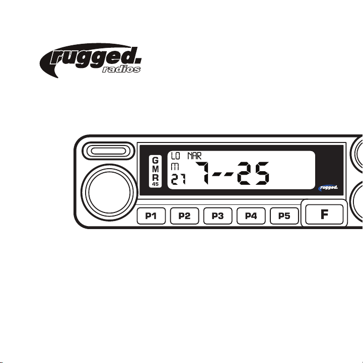
The GMR45 operates on GMRS (General Mobile Radio Service) frequencies, which require a
Federal Communications Commission (FCC) license. You must be licensed prior to operating
on channels 1-7, 15-22 or RP15-22 which comprise the GMRS channels of the GMR45.
Serious penalties may result from unlicensed use of GMRS channels, in violation of FCC rules,
as stipulated in the Communications Act’s Sections 501 and 502 (amended). You will be
issued a call sign by the FCC that should be used for station identification when operating your
radio on GMRS channels. You should also cooperate by engaging in permissible transmissions
only, avoiding channel interference with other GMRS users, and being prudent with the length
of your transmission time
To obtain a license or ask questions about the license application, contact the FCC at
1-888-CALL-FCC or go to the FCC’s website: http://www.fcc.gov and request Form 605.
FCC NOTICE

3
User Safety Information
Package Includes
Main Features
Initial Installation
Mobile Installation
DC Power Cable Connection
Replacing Fuses
Antenna Connection
Installing the Antenna
Accessory Connections
5-Pin Cable
External Speaker
Getting Acquainted
Front Panel Operation
Rear Panel Operation
Display
Microphone
Additional Features
Troubleshooting
Tone Codes
Changing Tone Codes
CTCSS
DCS
04
05
06
07
07
09
11
12
13
14
14
15
16
16
17
18
19
20
21
22
22
23
24
Standard GMRS Channels
GMRS Repeater Channels
Specifications
General
Receiver
Transmitter
Notes
CONTENTS
25
26
27
27
27
28
29

4
• Do not attempt to configure your radio while driving.
• This radio is designed for a 13.8V DC power supply. Do not use a 24V battery to
power on the radio.
• Do not place the transceiver in excessively dusty, humid or wet areas, nor unstable
surfaces.
• Please keep it away from interference devices (Such as TVs, generators, etc.)
• Do not expose the radio to long periods of direct sunlight or place it close to heating
appliances.
• If an abnormal odor or smoke is detected coming from the radio, turn off the power
immediately and contact your dealer.
• Do not transmit with high power for extended periods or the radio may overheat.
USER SAFETY INFORMATION

5
• Radio unit x 1
• Hand Mic x 1
• Mobile mounting bracket x 1
• DC power cable with fuse holder x 1
• Screw packs x 1
• Protection fuses x 1
PACKAGE INCLUDES

6
MAIN FEATURES
FEATURES:
Go Further with our industry leading 45-watt GMR45 mobile radio. More wattage equals
more power and range, giving you the ability to transmit long-distances when it matters.
Easily connect to intercom, headset, or any 5-pin accessory with the built-in Rugged Ready
pigtail cable! Loaded with channels and features, the GMR45 is ideal for installation into your
vehicle or setup at base camp.
• 45 Watt Radio
• 8 Repeater Channels
• 15 GMRS Channels (1-7 & 15-22)
• Easily connect to intercom, headset, or any 5-pin accessory with the
built-in Rugged Ready pigtail cable!
• Battery Voltage Display
• Adjustable Squelch
• KeyPad Lock
• External Speaker Port
• Clear Backlit Display
• Channel Scan Mode
• Dual-Tone Multi-Frequency (DTMF)*
*Enabled via software available from RT Systems.

MOUNTING BRACKET
TAPPING SCREW
(M5X20MM)
WASHER (M5)
CAR BODY
7
1. Install the mounting bracket in the vehicle using the supplied self-tapping screws and
flat washers.
INITIAL INSTALLATION
Mobile Installation: To install the radio select a safe and convenient location inside your vehicle
that minimizes danger to your passengers and yourself while the vehicle is in motion. Consider
installing the unit at an appropriate position so that knees or legs will not strike it during
sudden braking of your vehicle. Try to pick a well ventilated location that is shielded from direct
sunlight.
Caution: Extreme care should be exercised when drilling into dash to avoid damage to under
dash components.
MOBILE INSTALLATION

8
INITIAL INSTALLATION
• Determine the appropriate angle of the radio using the 3 screw hole positions on the side of the mounting bracket.
• Double check that all screws are tightened to prevent vehicle vibration from loosening the bracket or radio.
2. Position the radio, then insert and tighten the supplied hex/Phillips screws.
MOBILE INSTALLATION (CONT.)

9
INITIAL INSTALLATION
DC POWER CABLE CONNECTION
The vehicle battery must have a nominal rating of 12V. Never connect the radio to a 24V
battery. Be sure to use a 12V vehicle battery that has sufficient current capacity. If the
current to the radio is insufficient the display may darken during transmission or transmitting
output power may drop dramatically.
1. Route the DC power cable supplied with the radio directly to the vehicle’s battery
terminals using the shortest path from the radio. We suggest you do not use the
cigarette lighter socket as some cigarette lighter sockets introduce an unacceptable
voltage drop. The entire length of the cable must be dressed so it is isolated from heat,
moisture and the engine secondary (high voltage) ignition system/cables.
2. Confirm the correct polarity of the connections, then attach the power cable to the
battery terminals: Red connects to the positive (+) terminal and black connects to the
negative (-) terminal.

10
INITIAL INSTALLATION
DC POWER CABLE CONNECTION (CONT.)
3. Connect the DC power cable to the radio’s power supply connector. Press the
connectors firmly together until the locking tab clicks.

REPLACING FUSES
If the fuse blows, determine the cause then correct the problem. After the problem is
resolved replace the fuse. If newly installed fuses continue to blow, disconnect the power
cable and contact Rugged Radios for assistance. Only use fuses of the specified type and
rating otherwise the radio could be damaged.
Note: If you use the radio for a long period when the vehicle battery is not fully charged
or when the engine is OFF, the battery may become discharged and will not have sufficient
reserves to start the vehicle. Avoid using the radio in these conditions.
Fuse Location Fuse Current Rating
Transceiver 15A
Supplied accessory DC power cable 20A
11
INITIAL INSTALLATION

12
ANTENNA CONNECTION
Before operating, install an efficient well-tuned antenna. The success of your installation
will depend largely on the type of antenna and its correct installation. The radio can give
excellent results if the antenna system and its installation are given careful attention. Use a
50Ω impedance antenna and low-loss coaxial feed-line that has a characteristic impedance
of 50Ω, to match the radio input impedance. Coupling the antenna to the radio via feed-lines
having a impedance other than 50Ω reduces the efficiency of the antenna system and can
cause interference to nearby broadcast TV receivers, radio receivers and other electronic
equipment.
Note: Transmitting without first connecting an antenna or other matched load may damage
the radio.
Always connect the antenna to the radio before transmitting. All fixed stations should be
equipped with a lightning arrester to reduce the risk of fire, electric shock and radio damage.

EXTERNAL
SPEAKER PORT
COAX CABLE
ANTENNA
13
INSTALLING THE ANTENNA
For the best range, only the Rugged Radios GMRS POINT5 antenna should be used. Specific
installation requirements vary between vehicles. Use the following guidelines to install the
antenna. Where you locate your antenna does make a difference!
Important: Mount antenna up high and do not coil-up excess cable.
1. Avoid metal surfaces covered by fiberglass or vinyl that may affect radio range.
2. Mount the antenna as high on the vehicle as possible. The higher the better.
3. If possible, mount the antenna in the center of whatever surface you choose.
4. Be sure the mounting location is clean and dry before installing the antenna.
5. Route the antenna cable through an accessible entry point, such as a door or trunk
opening.
6. When routing the antenna cable inside the vehicle, keep the cable away from noise
sources, such as the ignition system, gauges, etc.
7. Exercise care to prevent cable damage. Make use of existing gaskets, grommets and
weather stripping to protect the cable along its route.

ACCESSORY CONNECTIONS
5-PIN CABLE
With its 5-pin interface cable, the GMR45 is Rugged Ready and can be easily connected to
headsets, intercoms, and other communication equipment.
14

ACCESSORY CONNECTIONS
EXTERNAL SPEAKERS
If you plan to use an external speaker, choose a speaker with an impedance of 8Ω. The
external speakerjack accepts a 3.5mm mono (2-conductor) plug. When an external speaker
is connected, the radios internal speaker is automatically disabled.
EX-SPK-X
15

16
GETTING ACQUAINTED
FRONT PANEL OPERATION
1
45 6 7 8 3 9
2

17
GETTING ACQUAINTED
REAR PANEL OPERATION
No. Port Function
1 Antenna Connector Connection for 50Ω antenna.
2 Ext. Speaker Terminal Terminal for optional external speaker..
3 Ext. Power Jack Terminal for connecting optional cable for use with
ignition key On/Off function.
The radio will auto power on when car is driving. The
radio will auto power off when car stops.
32
1
5-PIN ACCESSORY PORT

18
DISPLAY
GETTING ACQUAINTED
3 4 5
78910111112131415
6
1
2

1
19
No. Icon Function
1PTT Hold microphone approximately 4 inches from mouth, press the key
[#1], and speak into microphone.
MICROPHONE
GETTING ACQUAINTED

20
Feature Function
Channel Scan
In channel mode, this function is designed to monitor signal in every
channel.
1. In channel mode, press P3 key for 1s to enter into channel scan
2. Turn selector knob key to change scan direction.
3. Press any key except [F] key to exit.
Back Light
Color
1. Short press [F] then [P4] to enter the color selection menu.
2.Turn selector knob to select the desired light color, total 3 color for
choice.
3. Press [P5] key to confirm and exit.
Compander* Compander function will decrease the background noise and enhance
audio clarity, especially in long range communication.
*Enabled via software available from RT Systems.
ADDITIONAL FEATURES
GETTING ACQUAINTED
Other manuals for GMR45
1
Table of contents