Runtal Solea Original instructions

OOW
WN
NE
ER
R’’S
SMMA
AN
NU
UA
AL
L
&&IIN
NS
ST
TA
AL
LL
LA
AT
TI
IO
ON
NIIN
NS
ST
TR
RU
UC
CT
TI
IO
ON
NS
S
Thank you for purchasing the Runtal Solea. We are very proud of our
workmanship and quality, and we are certain that you will be
thoroughly satisfied with your new Runtal Solea. We urge you to
contact your local Runtal representative if you have comments or
questions.This manual is intended to show installation and care for your
Runtal Solea. Electrical connection, or hydronic piping should be
performed by qualified professionals. The plug-in model is intended for
quick and easy homeowner installation.
• The electric Runtal Solea must be used only when wall mounted in an
upright position with the control switch in the lower right hand corner.
RUNTAL NORTH AMERICA,INC.Tel: (978) 373-1666 ▲Fax (978) 372-7140 ▲www.runtalnorthamerica.com
S
OLEA
CONTENTS:
1 Runtal Solea Radiator
1 Mounting Hardware Package
1 Owner’s Manual
TOOLS REQUIRED:
Screw Drivers
Electric Drill
Allen Wrench (included)
Level
E
(1 ea)
Part G
(4 ea)
Correct Incorrect Incorrect Incorrect
ALL MODELS HARDWARE
ELECTRICAL MODELS (DIRECT WIRE)
Part F
(4 ea)
Part H
(1 ea)
Hydronic Models Only
Part M
(1 ea)
Part N
(1 ea)
Part O
(1 ea)
Part P
(1 ea)
A
(4 ea)
B
(4 ea)
Solea Installation Sheet.Q6 6/14/07 8:37 AM Page 1

I
IN
NS
ST
TA
AL
LL
LA
AT
TI
IO
ON
N
Use Cardboard
from Radiator
Packing Carton to
make Template
Please check the contents of the Runtal Solea carton to be
sure you have received all of the parts required. Runtal has
made every effort to ensure that all materials required for
mounting your unit have been included, and depending upon
specific installation conditions, you may have parts left over.
The mounting system has been designed for installation by one
person, but you may find an assistant helpful.
STEP 6FASTEN THE BRACKET SLEEVES TO THE WALL
Using the proper fasteners (either the metal anchors or #8 screws)
attach the mounting sleeves (Part B) to the wall. Fasten the sleeves
with the set screw positioned on the inside.
STEP 5DRILL HOLES
Drill holes for appropriate anchors in the middle of all four traced
circles. Use of the metal wall anchors will require a 5/16" hole; use
of the 1-1/2" screw will require a 1/16" pilot hole.
STEP 2ATTACH THE FOUR POSTS TO THE RADIATOR
STEP 3POSITION THE RADIATOR ON THE WALL
STEP 4DETERMINE WALL CONSTRUCTION
Position the four posts (Parts A) into their fixed positions on the unit.
All four posts supplied with the towel radiator must be used, half as top
supports and half as bottom supports.
To hang the unit either: (1) Ask an assistant to hold the unit against
the wall while you trace the four mounting posts. (2) Measure out
the post positions. (3) Make a template by placing the towel radiator
onto a posterboard or a large piece of the carton and tracing the
mounting posts. The template is then taped to the wall.
For solid wood or placement into blocking use the provided #8 x 1-1/2" long
screw with washers, (part F). For drywall construction use the included metal
anchors with washers, (part G). Runtal towel radiators are very sturdy and
care should be taken that they are securely hung using all four mounting posts.
STEP 1DETERMINE WIRING ORPIPING (IFOTHER THAN A PLUG-IN MODEL)
The electrician should start by providing the wiring to the Solea if the
model is electrical. The easiest termination of wires at the radiator is
accomplished using stranded conductors or 14/2 Romex (#12 AWG solid
wire is not recommended because of termination difficulties). If the unit
is hydronic, the plumber should determine the piping configuration.
Set Screws should be
facing toward the
inside of the radiator
Set Screws should be
facing toward the
inside of the radiator
Solea Installation Sheet.Q6 6/14/07 8:37 AM Page 2

STEP 7HANG THE TOWEL RADIATOR ON THE WALL
Insert all four radiator posts into the four wall sleeves and tighten
each set screw.
STEP 8MAKE THE ELECTRICAL OR PIPING CONNECTIONS
Please refer to electrical details or hydronic details below.
HYDRONIC PIPING DETAILS
STEP 9(HYDRONIC MODELS ONLY)
Install air vent, (part H) and properly seal with pipe dope.
BOTTOM TYPE- VERTICAL PIPING TO FLOOR BOTTOM TYPE- VERTICAL PIPING TO WALL
ELECTRICAL DETAILS
Connections for wires is as follows: Black to line, White to neutral, Green to ground
Electrical Installation Procedure:
All electrical towel radiators are designed for 120v AC 60HZ and must be GFCI protected. In the case of plug-in models
this protection is integrated into the cord provided. In the case of the direct wire models, GFIC protection must be
provided at the circuit breaker by a qualified electrician.
To install the direct wire model the electrician should follow these steps:
(1) Remove the two screws on the side of the control unit.
(2) Remove the control unit cover by pulling it forward.
(3) Remove the electrical connection access cover.
(4) Using the appropriate cement, cement Part M into Part N. Leave an 1/8” space
between these parts.
(5) Cut Part O to the required length and cement it to Parts N and P. A strain relief
(provided by the electrician ) is threaded to Part O.
(6) Run the electrical wires through the conduit, secure the strain relief and slide
Part M into the slot of the electrical junction box as shown.
(7) Connect the three wires as
indicated.
(8) Replace the electrical
connection access cover and
the control unit cover, fasten
in place with two screws.
Location of Conduit:
Starting at the bottom right side of the control go up 3/4” and over to the left 3/4”. This is
where you drill the hole in the wall to make the connection to the junction box on the unit.
Electrical Connection Access
3 Hour High
Select
Button
Ready Light
Low
Medium
High
Lights
14/2
Solea Installation Sheet.Q6 6/14/07 8:37 AM Page 3

MAINTENANCE
Your Runtal towel radiator has been designed to
require the absolute minimum maintenance and care
under normal use. However, care should be taken
when cleaning the surface of the towel radiator.
As with any electrical appliance, the electric towel
radiator should only be cleaned when in the OFF
position (unplugged if possible). The towel radiator’s
painted finish provides an elegant yet durable finish
to this welded steel product. Occasional cleaning of
this finish is best done with a water dampened cloth.
Under no circumstances should abrasive cleaners,
cloths or pads be used.
1) Read all instructions before using this heater.
2) Extreme caution is necessary when any heater is used by
or near children or invalids and whenever the heater is
left operating and unattended.
3) Always unplug heater when not in use.
4) Do not operate any heater with a damaged cord or plug
or after the heater malfunctions, or has been damaged
in any manner. Return the heater to an authorized
service facility for examination, electrical or mechanical
adjustment, or repair.
5) Do not run the cord under carpeting. Do not cover the
cord with throw rugs, runners, or the like. Arrange the
cord away from traffic areas and where it will not be
tripped over.
6) To disconnect heater, press control to off, then remove
the plug from the outlet.
7) Use this heater only as described in this manual. Any
other use not recommended by the manufacturer may
cause fire, electric shock, or injury to persons.
8) Avoid the use of an extension cord, because the
extension cord may overheat and cause a risk of fire.
However if you have to use an extension cord, the cord
should be NO. 18 AWG min. size and rated not less than
875 watts. For 900 watt models, the cord should be NO.
16 AWG min. size and rated not less than 1125 watts.
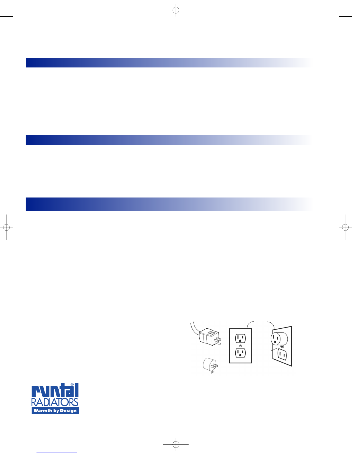
9) This heater is for use on 120 volts. The plug-in model has
a cord as shown in A of drawings below. An adapter as
shown at C is available for connecting three-blade
grounding-type plugs to two slot receptacles. The green
grounding lug extending from the adapter must be
connected to a permanent ground such as a properly
grounded outlet box. The adapter should not be used if
a three-slot grounded receptacle is available.
10) Connect to properly grounded outlets only.
11) Do not use outdoors.
SAVE THESE INSTRUCTIONS
IMPORTANT INSTRUCTIONS
When using electrical appliances, basic precautions should always be followed to reduce the risk of fire,
electric shock, and injury to persons, including:
OOP
PE
ER
RA
AT
TI
IO
ON
N&&MMA
AI
IN
NT
TE
EN
NA
AN
NC
CE
E
OPERATION
When plugged in or direct-wired the red ready light
will always remain on unless the power is interrupted.
This ready light is the basic off position. Towel
radiators come complete with 5 power settings (Off,
Low, Medium, High, and 3 Hour Timer at High
Setting). Press the select button to reach the desired
setting. While the fastest heating will be achieved on
the high setting (approximately 25 minutes to full
heat), the low or medium settings will produce
optimum heating efficiency. Cold rooms will benefit by
leaving the unit on longer. You may wish to use our
Electric Programmable Controller (EPC) for maximum
efficiency. Hydronic models are made for a closed-loop
hot water heating system only. Typical concerns are:
water temperature, flow rate, and controlling
thermostats and valves. Consult with the installing
heating contractor for the proper choice of the
available Hydronic models, and installation specifics.
RUNTAL NORTH AMERICA, INC.
Tel: (978) 373-1666
Fax (978) 372-7140
www.runtalnorthamerica.com
Cover of
grounded
outlet box
AB
Grounding Pin Metal Screw
Grounding Means
C
Solea Installation Sheet.Q6 6/14/07 8:37 AM Page 4
Table of contents
Popular Plumbing Product manuals by other brands

Dreamline
Dreamline ALLURE SHDR-4230728-01 installation instructions

Haufftechnik
Haufftechnik HSI90 KCH installation instructions

Delta
Delta 33825-DV Series manual

Delta
Delta IN2ITION 58470 Series manual

Delta
Delta Nicoli 35749LF Series quick start guide

infra world
infra world TrioSol Cedar 125 Instructions for use