Russound AW10-HSUB-BR User manual

AW10-LSUB-BR & AW10-HSUB-BR
Landscape Subwoofers
Product Manual
AW10-LSUB-BR AW10-HSUB-BR

2Landscape/Hardscape Subwoofer Product Manual
INTRODUCTION
Introduction
Thank you for selecting a premium landscape subwoofer from Russound.
This impressive subwoofer, designed to be installed by a professional, oers an
elegant, scalable platform for providing high quality audio enhancement to any
outdoor area in even the harshest environmental conditions. Specially designed
to withstand both extreme heat and cold, this subwoofer works great from the
humid, hot conditions of summertime in Florida to the bone-chilling cold of a
Minnesota winter.
Sample landscape layout with 2 subwoofers and 6 satellite speakers
Satellite Speaker Subwoofer
Satellite Speakers AW4-LS-BR
AW6-LS-BR
Subwoofers AW10-LSUB-BR
AW10-HSUB-BR
Russound Landscape Speakers

Landscape/Hardscape Subwoofer Product Manual 3
9) Make your wiring connections using the included weatherproof wire nuts
and, when the entire system is ready, turn on your amplier(s). See page 6-8
for information on wiring connections.
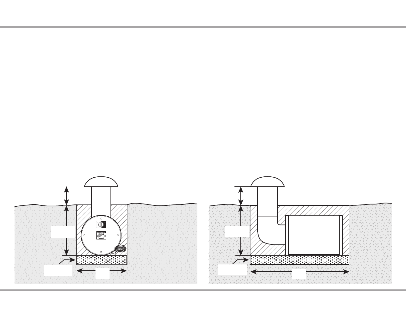
10) Lower the subwoofer into the hole. Russound recommends placing a 1-2”
layer of pea gravel or similar substrate at the bottom of the hole to ensure
proper drainage. When placed, the subwoofer and canopy should be level.
You can verify this with a bubble level.
11) Before covering the subwoofer and any wiring, verify the system operation
and that the proper volume levels are set. It is easy to adjust the subwoofer tap
setting before the subwoofer gets buried. Adjust the tap setting as necessary
for the desired sound level near the subwoofer.
12) When the entire system is veried and tap settings throughout have been
adjusted, replace the tap setting cover and hand tighten it until secure. You
can now bury the subwoofer and its wiring.
13) Make certain that the subwoofer does not rotate out of position while you
are lling the hole. Pack the dirt as you go for an even installation base.
14) When nished, the canopy bottom edge should be between 6” and 8”
above the ground level.
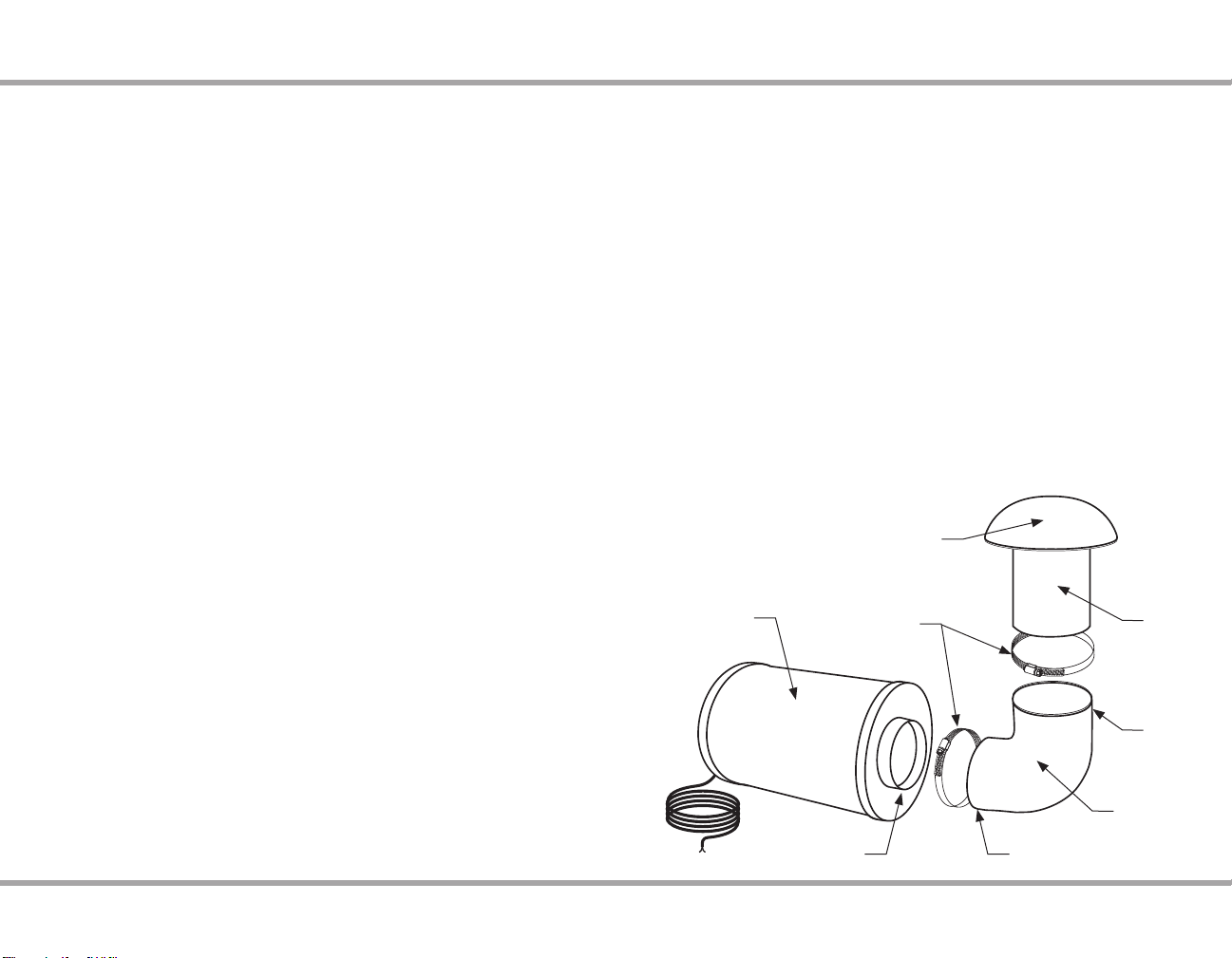
ASSEMBLING THE AW10-LSUB-BR
Stainless
steel clamp
Subwoofer body
port opening Small end
Large
end
Port
Tube
Silicone
Elbow
Subwoofer
Underground
Enclosure
Canopy
1) Unpack the contents of the box. Use caution when lifting the subwoofer.
The included carrying support rope should be utilized to help remove it from
the box.
2) Examine the silicone elbow. Note that one end is slightly larger than the
other. The smaller end attaches to the subwoofer body and the larger end
attaches to the port tube.
3) Place a stainless steel clamp ring on each end of the silicone elbow. There
are two dierent size clamp rings, one for the large end of the elbow, and one
for the smaller end of the elbow.
4) Attach the small end of the silicone elbow to the subwoofer body port
opening as shown.
5) Before tightening the clamp, determine the orientation that you would like
for the port tube. The speaker wire comes out of one edge of the subwoofer
and the tap setting adjustment is located near an edge of the rear panel. You
can rotate the elbow so that the speaker wire connection and tap setting
adjustment are best suited for your installation.
6) Once the orientation that you desire for the port tube is set, tighten the
clamp ring using a screwdriver until the ring is fully tightened. Making a good
seal is important both to prevent water penetration as well as to prevent audio
issues with the subwoofer.
7) Attach the canopy to the large end of the silicone elbow. Make sure that
the tube is fully seated and forms a 90 degree angle with the subwoofer.
When the tube is properly seated in the elbow, tighten the clamp ring using
a screwdriver until the ring is fully tightened. Making a good seal is important
both to prevent water penetration as well as to prevent audio issues with the
subwoofer.
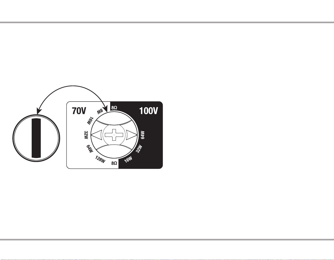
8) Adjust the tap setting switch. Remove the tap setting switch cover by turning
the cover counter-clockwise. Under the cover is the tap setting switch. Set
the tap setting to the appropriate position. Use the 8Ω setting for installation
with low impedance ampliers or receivers. Use any of the 70v/100v settings
for use with 70v/100v ampliers. Due to the nature of 70v/100v technology,
better bass performance will typically result if the subwoofer is used at 8Ω,
however the AW10-LSUB-BR is designed for operation at 70v/100v.

4Landscape/Hardscape Subwoofer Product Manual
Choosing a location for the subwoofer
The AW10-LSUB-BR is designed to cover approximately 2,000 ft2(185.8
m2). Sound from the subwoofer will carry in all directions and this means an
approximate spacing of 50’ (15.2 meters) between subwoofers. One important
consideration in positioning a burial subwoofer is avoiding placement near
walls or building foundations. Placing a subwoofer near a wall can increase
the bass by about 3dB and placing one in a corner will increase it by another
3dB. Keep in mind that if played at loud volume, this could induce unwanted
vibration or sound penetration into a home or adjacent building. Locate the
subwoofers near the primary outdoor listening areas, typically on the outer
edges of a space, and not next to a home or building. Other considerations
to keep in mind are the ease of installation at the location, and the ease of
running wires to that location.
The subwoofer is made of materials designed for rugged outdoor use, and
will withstand occasional hits from common landscape tools, but can be
damaged if struck by lawn mowers or other motorized equipment. Placing the
subwoofer near bushes, shrubs, or rock decorations may help protect it from
being struck by lawn maintenance equipment.
The subwoofer requires a hole size of approximately 15”Wide x 30” Long x 17-19" Deep.
(38.1 x 76.2 x 43.2-48.3 cm)
Make sure that the desired location:
1) Has the required mounting depth.
2) Is not near a building wall or foundation that would allow unwanted sound
noise to intrude.
3) Has proper drainage. Placing a subwoofer in a low-lying area that is prone
to ooding can damage the subwoofer if water levels rise enough for water to
enter through the underside of the port tube canopy.
4) Is free of any obstructions or underground utilities. In the United States, you
must dial 811 (1-888-344-7233) before any digging in order for underground
utilities to be marked prior to any digging.
The depth of the mounting hole will aect the nished look of the subwoofer.
The subwoofer is recommended to be installed at a depth of 15-17”. This
will leave approximately 6-8” of the subwoofer port tube and cap above the
ground after the installation.
Russound recommends adding a layer of 1-2” of pea gravel at the bottom of
the hole to facilitate drainage around the base of the subwoofer. If adding
gravel, make sure to dig the hole slightly deeper to accommodate the layer of
gravel.
2” Gravel
15-17”
6-8”
30”
(15.2-20.3 cm)
(38.1-43.2 cm)
(76.2 cm)
(5 cm)
15”
2” Gravel
15-17”
6-8”
(15.2-20.3 cm)
(38.1-43.2 cm)
(38.1 cm)
(5 cm)
INSTALLING THE AW10-LSUB-BR

Landscape/Hardscape Subwoofer Product Manual 5
Remove weatherproof
rear cap by turning it
counterclockwise
AW10-LSUB Tap Settings:
70V: 8W, 16W, 32W, 64W, 128W
100V: 16W, 32W, 64W
8Ω Bypass
Painting
The exposed outer sides and top of the landscape subwoofer can be easily
painted to match any landscape décor. It is recommended that these be
painted prior to installation. Any high quality spray paint will do. Be careful not
to paint the underside of the canopy of the AW10-LSUB-BR as there is a mesh
insect/rodent guard at the base that can become clogged and interfere with
sound transmission if it is blocked. Mask this area when painting. Similarly, do
not paint the underside of the AW10-HSUB-BR and take care not to paint the
screw threads of the adjustable feet.
Wiring Connections
Note: Before connecting any wires, make certain that the tap setting switch
(located by unscrewing the rear cover cap from the speaker) is set to either a
70v/100v position for 70v/100v systems or to the 8Ω position when used with
a standard low impedance amplier or receiver.
When you are ready to connect the loudspeaker wiring, make certain that you
leave enough slack in the wiring to completely protect the wire after testing
the system by burying it at least 6” underground or whatever minimum
depth your local building code requires, or by protecting the wire in conduit.
Leaving a wire exposed can lead to inadvertent damage during lawn mowing
or trimming. Keeping the wire properly protected is essential to preventing
unwanted service calls in the future.
While maintaining the proper polarity of the wires, twist the wire leads
together and insert them into the enclosed waterproof wire nuts. Tighten the
nuts securely and then test the connection before burying the wire, closing
any junction boxes, or lling any wire trenchwork.
Adjusting the tap setting (volume level)
When used as a 70v/100v speaker, the tap setting should be adjusted for
each speaker in the system. Keep in mind that the total wattage number of
all speakers connected to the same amplier including any subwoofers should
not exceed the amplier’s power rating, always leaving 20% of power as
headroom.
When you have nished adjusting the tap settings, make sure to securely
re-attach the protective tap setting cap of the speaker and hand-tighten it.
Adjustable Feet for Easy Leveling (AW10-HSUB Only)
If installing the AW10-HSUB-BR on an uneven surface, each of the three
mounting legs can be adjusted so that the subwoofer can be kept level. Simply
unscrew any of the leg(s) and use the included hex wrench to counter tighten
the two locking nuts into the desired position.
INSTALLING AW10-LSUB AND AW10-HSUB
AW10-HSUB Tap Settings:
70V: 8W, 16W, 32W, 64W, 128W
100V: 16W, 32W, 64W
8Ω Bypass
The above illustration shows a setting of 8W
for a 70V system and 16W for a 100V system

6Landscape/Hardscape Subwoofer Product Manual
WIRING INFO 70V/100V OPERATION
Speaker cable
Wiring speakers for 70V/100V systems is simple and easy. A single run of
2-conductor, stranded wire is run to every speaker location leaving a small
loop (2-3 feet is usually more than sucient depending on the speakers and
their mounting type) at each speaker location. You can place additional loops
for future expansion or for making speaker location changes if needed.
Note: This is very dierent from typical low-impedance wiring used for
residential audio installations where a dedicated run of wire goes from each
speaker back to the amplier/receiver. 70V/100V wiring uses much less wire
and the wire used can be a much higher gauge (thinner wire) even though it is
used in a longer run.
Here is a chart showing some of the dierences possible among wire lengths
for both low impedance (4Ω-8Ω) and high impedance (70V/100V) systems:
Speaker Cable Length for Various Gauges at Low and High Impedance
Power Loss in Cable (% Loss & dB Loss)
4 Ohm Speakers 8 Ohm Speakers 70V Speakers
11% 21% 50% 11% 21% 50% 11% 21% 50%
0.5 dB 1 dB 3 dB 0.5 dB 1 dB 3 dB 0.5 dB 1 dB 3 dB
277’
84m
571’
174m
1930’
588m
554’
169m
1141’
348m
3859’
1.2km
2.6mi
4.14km
5.3mi
8.5km
18mi
29km
174’
53m
359’
109m
1214’
370m
349’
106m
718’
219m
2428’
740m
1.6 mi
2.6km
3.4 mi
5.5km
11.3 mi
18.1km
110’
33.5m
226’
69m
764’
233m
219’
67m
452’
138m
1528’
466m
1mile
1.6km
2mi
3.4km
7mi
11.4km
69’
21m
142’
43m
480’
146m
138’
42m
284’
87m
959’
292m
3376’
1km
1.3 mi
2.1km
4.5mi
7.2km
43’
13m
89’
27m
302’
92m
87’
27m
179’
55m
604’
184m
2127’
648m
4380’
1.3km
2.8mi
4.5km
27’
8m
55’
17m
185’
56m
53’
16m
110’
38m
371’
113m
1305’
398m
2687’
819m
1.7mi
2.8km
17’
5m
35’
11m
117’
36m
34’
10m
69’
21m
234’
71m
823’
251m
1694’
516m
1mi
1.75km
11’
3m
22’
7m
74’
23m
21’
6m
44’
13m
147’
45m
518’
158m
1068’
331m
3610’
1.1km
7’
2m
13’
4m
46’
14m
13’
4m
27’
8m
91’
28m
321’
98m
661’
201m
2234’
681m
4’
1m
9’
3m
29’
9m
8’
2m
17’
5m
57’
17m
202’
62m
417’
127m
1409’
429m
AWG
6
8
10
12
14
16
18
20
22
24

Landscape/Hardscape Subwoofer Product Manual 7
WIRING INFO 70V/100V OPERATION
Important
Because outdoor loudspeakers often have buried speaker cable, please make
certain to fully test an entire system and make sure that all wiring, speakers,
volume level, etc. meets your desired needs before lling in any trenching or
covering any speaker cable or wiring connections.
Note: Unlike traditional residential audio, 70V/100V systems are typically run
in mono sound so that only a single two-conductor wire run is necessary for
the speakers. If you want to use multiple wire runs for zoning speakers or
other purposes, each 2-conductor wire needs to be independently run back to
its own amplier or amplier terminals if using a multi-channel amplier.
1. At each speaker location, cut the loop of wire at the speaker location
2. Strip 1 to 2 inches (2.5 to 5 cm) o the end of the cable jacket. Then strip
½-inch (1.3 cm) of insulation o each wire.
3. Twist the wire strands together so there are no strands separated from the
bundle.
4. Connect the wires to the speaker terminals, being sure to observe proper
polarity. For standard speaker cable with red and black wires, connect both
red wires (the red wire coming from the 70V/100V connection on the amplier
or the previous speaker if there was one AND the red wire going to the next
speaker if there is an additional speaker) to the red positive (+) terminal and
both black wires (the black wire coming from the COM connection of the
70V/100V amplier or the previous speaker if there was one AND the black
wire going to the next speaker if there is an additional speaker) to the black
negative (–) terminal.
Note: Some speaker cables may have other ways of designating polarity. Cable
with a clear jacket has a copper-colored wire for positive and a silver-colored
wire for negative. In a cable with white and black wires, the white is positive
(70V or 100V) and the black is negative (COM). Cable with both wires the same
color may have grooves, ribs, or stripes on the positive wire to identify it.
5. Check to make sure there are no stray strands of wire outside the terminals. If
there are, remove the wire, twist the strands together, and reconnect the wire
to the terminal.
6. At the nal loudspeaker, the only wires connected will be the ones coming
from the previous loudspeaker (or from the amplier if there is only one
speaker in the system).
Amplier
Speaker Out
70V COM
AW4-LS-BR AW6-LS-BR
AW10-LSUB-BR - OR - AW10-HSUB-BR

8Landscape/Hardscape Subwoofer Product Manual
Adjust the Tap Settings
The tap settings will aect the overall volume of each loudspeaker in the
system. When designing a 70V/100V system, care must be taken not to
exceed the power rating of the amplier or dangerous clipping may occur.
Clipping is the most common cause of damage to loudspeakers and should
be avoided at all times. The standard rule is to design a system that leaves
20% of the amplier’s rated power as a reserve. For example, with a 300-
watt amplier, speakers should never be set with taps that total higher than
240-watts. The ampliers total load is determined by adding the wattage of
each speaker. When thicker wire or exceptionally long wire runs are used, there
is an additional component of current loss due to the cable that can become
signicant and must be considered in the calculation.
For a 70V/100V system, most installations are designed to blanket an area using
more loudspeakers at a lower tap setting rather than using fewer speakers at
a higher tap settings. This is done to avoid hot spots where very loud sound
is heard in certain areas and less in others. It is much more common for 70V
speakers to be set at their lowest tap setting than at their highest, but each
installation may require adjustments due to the application or environment.
WIRING INFO 70V/100V OPERATION
Speaker cable
The amount of wire needed varies with speaker placement. Label speaker
wires with left, right, and location.
Use Russound AW series speaker cable or any reputable brand of 16 to 12
gauge multi-stranded wiring for amplier- to-speaker connections.
Wire is measured in gauges: the greater the number, the smaller the wire. The
gauge of wire needed is determined by the distance between the amplier/
receiver and the speakers. The longer the run, the heavier the gauge needed.
Use the following chart as a guide:
Length Minimum Gauge
0' to 100' 16
50' to 150' 14
100' to 200' 12
The standard colors on the terminals are red Positive (+) and black Negative (-).
If the wire has transparent insulation, one conductor will be copper-colored
(+) and the other silver-colored (-). If the wire has an opaque insulation, the
conductors are dierentiated by a series of ribs or grooves, a stripe, or dotted
line on one conductor. Use and mark these as the Positive (+) conductor.
Typical usage of speaker wire conductors
-+-+
AW10-LSUB Tap Settings:
70V: 8W, 16W, 32W, 64W, 128W
100V: 16W, 32W, 64W
8Ω Bypass
AW10-HSUB Tap Settings:
70V: 8W, 16W, 32W, 64W, 128W
100V: 16W, 32W, 64W
8Ω Bypass

Landscape/Hardscape Subwoofer Product Manual 9
WIRING INFO 8 OHM OPERATION
Tap Setting Knob
When using the subwoofers
with a low impedance
system (such as with a 4Ω
or 8Ω amplier or receiver),
make sure that the tap
setting switch is set to the
8Ω position. This is the only
appropriate setting when
using the speaker with a low
impedance amplier.
Prewiring
Run a separate 2-conductor stranded copper speaker cable of at least 16 AWG
(1.5 mm) from the amplier to each speaker.
When running a speaker cable parallel to an AC power cable, keep them at
least 24 inches (60 cm) apart to minimize electromagnetic interference. If the
speaker cables must cross AC wiring, cross them at right angles.
Leave about 2 feet (0.6 m) of cable at each end for connecting to the speakers
and amplier. Label the cables so you will know which cable connects to each
keypad or amplier output channel.
• Avoid running speaker wires close to house electrical wiring for any
distance. If you have to run them parallel, leave two feet between the
wiring. Speaker wires should cross AC lines at a 90° angle.
• The entire path between speakers and amplier should be clear and
unobstructed. Conrm the placement for the wall port close to the
intended location of the amplier or receiver.
• Label speaker wires at each end with left and right and location.
Impedance matching for ampliers and speakers
If you intend to use more than one pair of speakers at a time it’s important
to consider both the impedance of the speakers and the capabilities of the
amplier or receiver. Not all ampliers or receivers can safely operate two sets
of speakers at once.
Connecting the speaker
With power to the amplier or receiver disconnected:
1. Strip 1 to 2 inches (2.5 to 5 cm) o the end of the cable jacket. Then strip ½
inch (1.3 cm) of insulation o each wire.
2. Twist the wire strands together so there are no strands separated from the
bundle.
3. Connect the wires to the speaker terminals, being sure to observe proper
polarity. For standard speaker cable with red and black wires, connect the
red wire to the red positive (+) terminal and the black wire to the black
negative (–) terminal.
Note: Some speaker cables may have other ways of designating polarity.
Cable with a clear jacket has a copper-colored wire for positive and a silver-
colored wire for negative. In a cable with white and black wires, the white is
positive and the black is negative. Cable with both wires the same color may
have grooves, ribs, or stripes on the positive wire.
4. Check to make sure there are no stray strands of wire outside the terminals.
If there are, remove the wire, twist the strands together, and reconnect the
wire to the terminal.

10 Landscape/Hardscape Subwoofer Product Manual
AW10-LSUB-BR Landscape Speaker
Type: Full Bandpass Subwoofer
Woofer: 10” (254mm) PP Weatherproof Cone
(rubber surround)
Impedance: 8Ω - 70/100V
Frequency Response: 30Hz - 200Hz
SPL: 90 dB @1w/1m
Dimensions: Woofer Enclosure: 12.7“ dia x 18.3”L (32.3 x 46.5cm)
Canopy: 10.8” dia (27.4)
Weight: 29 lbs (13.1 kg)
AW10-HSUB-BR Landscape Speaker
Type: Down Firing Subwoofer
Woofer: 10" (254mm) DVC Long Throw Poly
(Santoprene Surround)
Impedance: 8Ω - 70/100V
Frequency Response: 38Hz-300Hz +/- 3dB
SPL: 90 dB @1w/1m
Dimensions: 16” dia x 17-3/4"H (40.6 x 45cm)
Weight: 34 lbs. (15.4 kg)
Speaker care
These sealed construction speakers are made of durable materials that need
very little care. Occasionally wipe them with a soft, damp cloth. Do not use any
harsh detergents, chemical solvents, or abrasive materials on your speakers,
and do not spray water or other liquids into the grilles.
TECHNICAL SPECIFICATIONS

Landscape/Hardscape Subwoofer Product Manual 11
The Russound AW10-LSUB-BR Speaker is guaranteed against all defects in materials and
workmanship for ve (5) years from the date of purchase. During this period, Russound
will replace any defective parts and correct any defect in workmanship without charge
for either parts or labor.
For this warranty to apply, the unit must be installed and used according to its written
instructions. If service is necessary, it must be performed by Russound. The unit must
be returned to Russound at the owner’s expense and with prior written permission.
Accidental damage and shipping damage are not considered defects, nor is damage
resulting from abuse or from servicing by an agency or person not specically
authorized in writing by Russound.
This Warranty does not cover:
• Damage caused by abuse, accident, misuse, negligence, or improper installation
or operation
• Power surges and lightning strikes
• Normal wear and maintenance
• Products that have been altered or modied
• Any product whose identifying number, decal, serial number, etc. has been altered,
defaced or removed.
Russound sells products only through authorized Dealers and Distributors to ensure
that customers obtain proper support and service. Any Russound product purchased
from an unauthorized dealer or other source, including retailers, mail order sellers and
online sellers will not be honored or serviced under existing Russound warranty policy.
Any sale of products by an unauthorized source or other manner not authorized by
Russound shall void the warranty on the applicable product.
Damage to or destruction of components due to application of excessive power voids
the warranty on those parts. In these cases, repairs will be made on the basis of the
retail value of the parts and labor. To return for repairs, the unit must be shipped to
Russound at the owner’s expense, along with a note explaining the nature of service
required. Be sure to pack the unit in a corrugated container with at least three (3) inches
of resilient material to protect the unit from damage in transit.
Before returning a unit for repair, call Russound at (603) 659-5170 for a Return
Authorization number. Write this number on the shipping label and ship to:
Russound
Attn: RA# (Insert your RA number here)
1955 Wehrle Dr
Williamsville NY 14221
Due to continual eorts to improve product quality as new technology and techniques
become available, Russound/FMP, Inc. reserves the right to revise system specications
without notice.
WARRANTY

©2022 Russound/FMP Inc. All rights reserved.
All trademarks are the property of their respective owners.
Specications are subject to change without notice.
Russound is not responsible for typographical errors or omissions.
Russound
200 International Drive, Suite 155
Portsmouth, NH 03801 USA
Tel: 603.659.5170
01.2022 - Rev.2
This manual suits for next models
1
Table of contents
Other Russound Subwoofer manuals