2
CONTENTS
Contents
1.0 IMPORTANT SAFETY INFORMATION ............................................................3
2.0 GENERAL INFORMATION ...............................................................................4
2.1 Introduction ....................................................................................................4
2.2 Importance of Quality Installation .................................................................4
2.3 System Sizing and Selection.........................................................................4
2.4 Importance of Proper Indoor/Outdoor Match-Ups........................................5
2.5 Checking Product Received ..........................................................................5
2.6 Efficiency Testing Notice ...............................................................................5
2.7 Compressor Break-In Notice .......................................................................5
3.0 UNIT SPECIFICATIONS ....................................................................................6
3.1 Model Number Nomenclature........................................................................6
3.2 Available Models............................................................................................6
3.3 Electrical and Physical Data..........................................................................6
4.0 INSTALLATION..................................................................................................8
4.1.1 Tools Required for Installing and Servicing R-410A Models.................8
4.1.2 Specications of R-410A .......................................................................8
4.1.3 Quick-Reference Guide for R-410A ......................................................8
4.1 Tools and Refrigerant.....................................................................................8
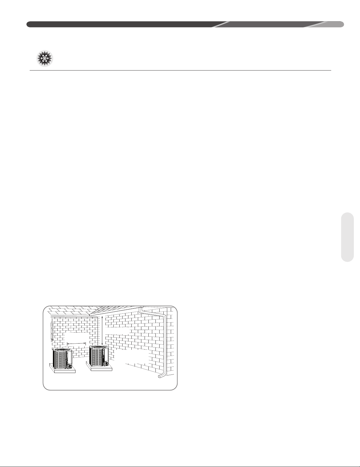
4.2.1 Allowable Clearances............................................................................9
4.2.2 Operational Issues Related to Unit Location........................................9
4.2 Choosing a Location......................................................................................9
4.2.3 Corrosive Environment........................................................................10
4.2.4 Customer Satisfaction Issues .............................................................10
4.3.1 Unit Mounting Methods .......................................................................10
4.3.2 High Wind and Seismic Tie-Down Methods.......................................10
4.2 Choosing a Location (cont.).........................................................................10
4.3 Mounting Unit...............................................................................................10
4.3.3 Elevating Unit ......................................................................................11
4.4.1 Replacing Existing Systems................................................................12
4.4.2 Line Set Length and Fitting Losses ....................................................12
4.4.3 Liquid Line Selection...........................................................................12
4.4 Refrigerant Line Set Selection.....................................................................12
4.4.4 Suction Line Selection.........................................................................14
4.4.5 Long Line Set Considerations.............................................................14
4.4.5.1 Determining if Long Line Set Length Requirements Apply ..........14
4.4.5.2 Oil Return to Compressor.............................................................14
4.4.5.3 Refrigerant Migration During Off Cycle........................................14
4.4.5.4 Maximum Liquid Pressure Drop ...................................................15
4.4.5.5 Liquid Line Refrigerant Flashing...................................................15
4.4.5.6 Oil Level Adjustment for Long Line Set Applications ...................15
4.4.5.7 Capacity Losses............................................................................15
4.5 Line Set Installation .....................................................................................15
4.5.1 Important Tubing Installation Practices...............................................15
4.5.2 Relative Location of Indoor and Outdoor Units ..................................16
4.5.2.1 Indoor and Outdoor Unit Near Same Level......................................16
4.5 Line Set Installation (cont.) ..........................................................................16
4.5.2.2 Outdoor Unit Below Indoor Unit.......................................................17
4.5 Line Set Installation (cont.) ..........................................................................17
4.5.2.3 Outdoor Unit Above Indoor Unit ...................................................18
4.5 Line Set Installation (cont.) ..........................................................................18
4.5.3 Tubing Connections ............................................................................19
4.5 Line Set Installation (cont.) ..........................................................................19
4.6 Initial Leak Testing ......................................................................................20
4.7 Evacuation ...................................................................................................20
4.8 Final Leak Testing........................................................................................20
4.9 Control Wiring ..............................................................................................21
4.10 Typical Control Wiring Connections...........................................................21
4.11 Power Wiring ..............................................................................................22
4.12 Grounding...................................................................................................22
4.10 Typical Control Wiring Connections (cont.) ...............................................22
5.0 SYSTEM START-UP & REFRIGERANT CHARGING....................................23
5.1 System Start-Up Overview ..........................................................................23
5.2 Initial System Power-Up ..............................................................................23
5.4 Refrigerant Charging ...................................................................................24
5.4.1 Measurement Device Set-Up..............................................................24
5.4.2 Preliminary Charging by Weight .........................................................24
5.4.3 Preliminary Charging by Pressures ....................................................25
5.4.4 Final Charging by Liquid Subcooling ..................................................25
5.4.5 R-410A Temperature Pressure Chart .................................................26
5.5 Completing Installation................................................................................26
6.0 SEQUENCE OF OPERATION.........................................................................26
7.0 COMPONENTS & CONTROLS .......................................................................27
7.1 Compressor ..................................................................................................27
7.2 Fan Motor .....................................................................................................27
7.3 Outdoor Fan .................................................................................................27
7.4 Compressor Contractor................................................................................27
7.5 Compressor/Fan Motor Capacitor ...............................................................27
7.6 Compressor Crankcase Heat (CCH) ...........................................................27
7.7 High- and Low-Pressure Controls (HPC and LPC) .....................................27
7.8 Compressor Hard Start Components..........................................................27
8.0 ACCESSORIES................................................................................................28
8.1 Compressor Time Delay ..............................................................................28
8.2 High Pressure Control .................................................................................28
8.3 Low Pressure Control ..................................................................................28
8.4 Low Ambient Control ...................................................................................28
8.5 Compressor Hard Start Kit ..........................................................................28
8.6 Compressor Crankcase Heater...................................................................28
8.7 Compressor Sound Enclosure.....................................................................28
9.0 DIAGNOSTICS & TROUBLESHOOTING.......................................................29
9.1 Cooling Mechanical Checks Flowchart .......................................................29
9.0 DIAGNOSTICS & TROUBLESHOOTING.......................................................30
9.2 General Troubleshooting Guide ..................................................................30
9.0 DIAGNOSTICS & TROUBLESHOOTING.......................................................31
9.3 Service Analyzer Charts..............................................................................31
9.4 Troubleshooting Tips ...................................................................................35
10.0 OUTDOOR UNIT MAINTENANCE................................................................36
10.1 Outdoor Coil Cleaning................................................................................36
10.2 Cabinet Cleaning and Care .......................................................................36
10.3 Motor Lubrication .......................................................................................36
10.4 Replacement Parts ....................................................................................36
11.0 WIRING DIAGRAMS......................................................................................37
12.0 INSTALLATION NOTES ................................................................................38
List of Tables
Table 1: Available Models......................................................................................6
Table 2: Electrical Data and Physical Data..........................................................6
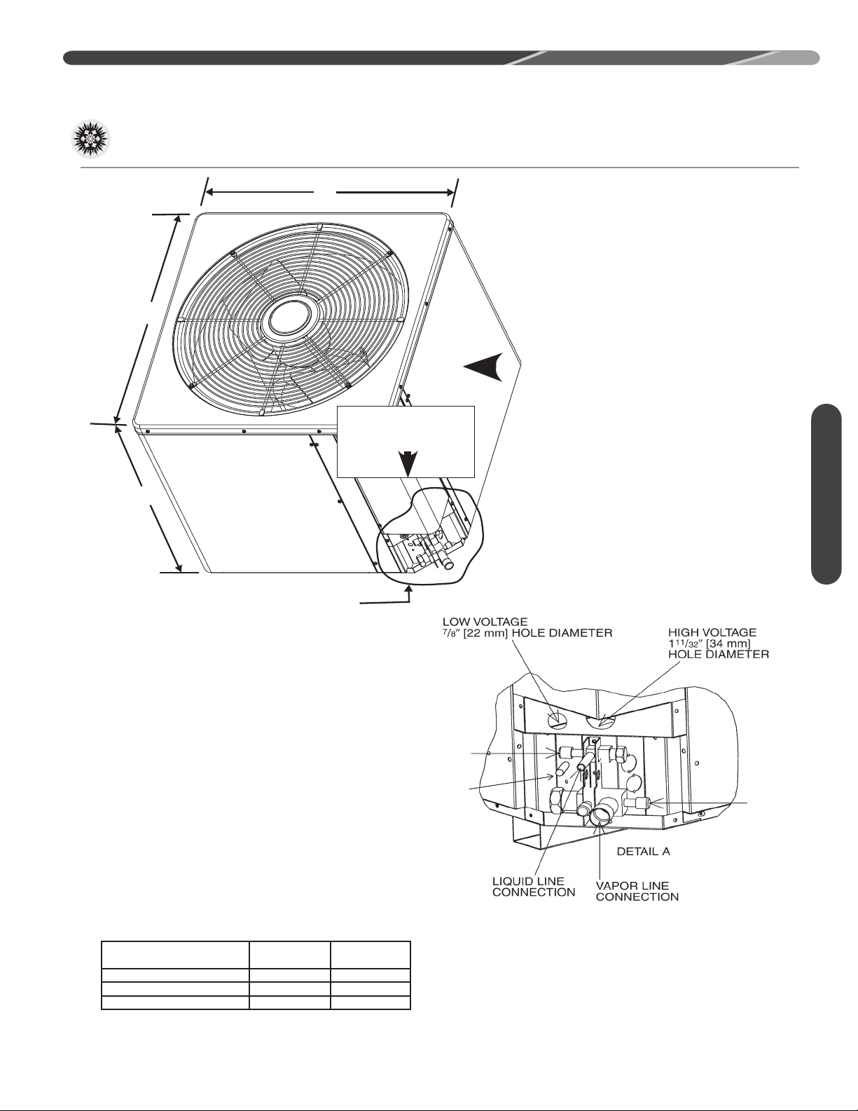
Table 3: Dimensions...............................................................................................7
Table 4: Equivalent Length for Fittings: ft [m] .................................................12
Table 5A: Refrigerant Line Sizing Chart (English Units).................................13
Table 5B: Refrigerant Line Sizing Chart (Metric Units) ...................................13
Table 6: Example Table .......................................................................................14
Table 7: Factory Installed Crank Case Heaters.................................................14
Table 8: Voltage Ranges ......................................................................................22
Table 9: Altitude Temperature Rise Ranges .....................................................24
Table 10: R-410A Temperature Pressure Chart.................................................26
Table 11: Maximum System Charge Values ......................................................27
Table 12: Troubleshooting Guide .......................................................................30
Table 13: Service Analyzer Chart .......................................................................31
Table 14: Cooling Mode Trouble Shooting Tips................................................35