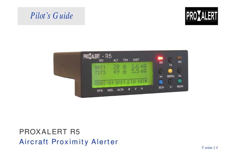
Ryan TCAD 9900 User manual

PILOT'S HANDBOOK
9900 Series
Models 9900, 9900A and 9900B
This Revision Incorporates The
Multifunction Display Interface Supplement
to the Pilot's Handbook

Copyright 1998 P/N: 32-2302
RYAN INTERNATIONAL CORPORATION Revision: 3
4800 Evanswood Drive •Columbus, Ohio 43229 November 9, 1998
PILOT'S HANDBOOK
9900 Series
Models 9900, 9900A and 9900B
This Revision Incorporates The
Multifunction Display Interface Supplement
to the Pilot's Handbook

i
PREFACE
____________________________________
____________________________________
Thank you for becoming an owner of the Ryan TCAD. You
have demonstrated a concern for yourself, those who depend on
you for flying safely, and a concern for others who share the
airspace around you.
Now you can fly with greater confidence, and greater peace of
mind, knowing you are equipped with the latest technology
available for collision alert.
This Operation and Performance Handbook is intended as a
guide to the capabilities and operation of the Ryan TCAD 9900
Series. By carefully reading this manual, you will become
familiar with TCAD, and how to get the best performance from
your investment.
WARNING
The TCAD does not detect all aircraft, and is designed as a
backup to the See and Avoid concept, and the ATC Radar
environment. See TCAD Limits in Appendix 2.
Refer to this handbook for TCAD limits.
CAUTION: This handbook, and the Ryan TCAD, are advisory
only. Any action recommended in this manual, or made as a
result of data supplied by the TCAD, must be in accordance with
applicable FARs and common sense. The pilot in command is
the final authority as to the operation of the aircraft.

ii
Features of the Ryan TCAD 9900 Series
Feature 9900 9900A 9900B
Top and bottom antenna
capability for maximum
coverage above and below the
aircraft
Yes Yes Yes
Selectable Air Traffic Shield –
TCAD Electronically monitors
for traffic within the airspace
you define. You get traffic
coverage with minimal
distraction!
Yes Yes Yes
Traffic Display -You get the
traffic information in the same
place, in the same format, in
bright LED characters.
Yes Yes Yes
Digital Profile Display with
Trend Data –Gives you a quick
indication of the significance of
the traffic to your safety.
Yes Yes Yes
Additional threat display for
additional, less threatening
traffic Yes Yes Yes
Ground mode –Shows traffic
in the air before departure
without displaying ramp traffic. Yes Yes Yes
Approach Mode –Eliminates
the display of traffic on the
ground while on approach. Yes Yes Yes

iii
Features of the Ryan TCAD 9900 Series, Continued
Feature 9900 9900A 9900B
Tone Alerts for traffic and
altitude alerter -TCAD
provides an audible monitor to
reduce pilot workload.
Yes Yes Yes
MSL Altitude of traffic –
Provides quick correlation to
the traffic on TCAD and ATC
traffic announcements. Allows
you to better understand and
anticipate ATC instructions.
Yes Yes Yes
Host Altitude Display –A
means to confirm and
crosscheck your altimeter. Yes Yes Yes
Altitude Alert –Warns when
you are about to reach your
assigned altitude, or as a
secondary alerter for cabin
announcements or passing
through FL180.
Yes Yes Yes
Automatic transition from
Ground Mode to Enroute, to
minimize pilot workload. Yes Yes Yes
Density Altitude –To easily
determine this important
parameter, for takeoff
requirements and engine
performance.
Yes Yes Yes

iv
Features of the Ryan TCAD 9900 Series, Continued
Feature 9900 9900A 9900B
Unrestricted Mode –Enlarges
the monitored area and mutes
audible alerts until the traffic is
closer.
±5000
feet &
3iNM
±10,000
Feet & 6
iNM
±10,000
Feet & 6
iNM
Upgrade Capability –Your
TCAD is designed for future
enhancement and greater
capability
Yes, to
9900A Yes, to
9900B
Yes,
future
upgrades
Remote Mute -Yoke mounted
mute button if desired. Yes Yes Yes
½ 3ATI Display -Fits in an
instrument location or in the
avionics stack. Yes Yes Yes
Three Programmable Shields –
To define the volume of
airspace monitored based on
aircraft performance and your
preferences.
Fixed
shield Yes Yes
Maximum Range –The
horizontal limits for tracking
traffic around your aircraft. 3 iNM
6 iNM
for Mode
S targets,
5iNM
for Mode
A or C
6 iNM
for Mode
S targets,
5iNM
for Mode
A or C
Dynamic Shield, displays
traffic beyond selected shield
during high-speed climbs and
descents
Yes Yes Yes
Voice Alert for traffic –Voice
warning for traffic alerts. No Yes Yes

v
Features of the Ryan TCAD 9900 Series, Continued
Feature 9900 9900A 9900B
Displays Mode A squawk
(when available). To quickly
determine if traffic is VFR,
IFR, or communicating with
ATC.
No Yes Yes
Displays N-number of Mode-S
equipped aircraft. Lets you
quickly track and correlate the
TCAD data with traffic
announced on the radio.
No Yes Yes
Provides for Interface with
other Multifunction Displays. No No Yes
Displays bearing to the target
for optimal visual tracking. No No Yes

vi
This Handbook is organized into the
Following sections:
IIntroduction
Describes the product, operating concept, technology, and
components of the Ryan TCAD 9900 Series.
II Operator Controls & Basic Displays
Illustrates the controls and display features of the Ryan TCAD
9900 Series.
III The Air Traffic Shield
Introduces and describes use of the Air Traffic Shield.
IV Threat Acquisition
Describes recommended procedures when threats are acquired
by the TCAD.
VAltitude Displays
Explains display of MSL altitudes and Flight Levels
VI Altitude Alert
Describes operation of the Altitude Alert.
VII Density Altitude
The Density Altitude function is described.

vii
VIII Flying with TCAD
Describes operation of TCAD and illustrates a flight from
startup to landing.
IX Operating Tips
Contains useful suggestions to maximize the utility of the Ryan
TCAD.
XBuilt-In Test & Fault Displays
Describes the TCAD built-in test function and fault displays.
Appendix 1 Setup
Describes parameters that can be set by the pilot.
Appendix 2 Limits
Describes limitations of the TCAD and how those limitations
can affect performance of the equipment.
Appendix 3 Excerpts
Presents excerpts from FAA Advisory Circular 90-48C, Pilot's
Role in Collision Avoidance.
Appendix 4
Contains Specifications, Factory Settings, Warranty, Disclaimer,
and Customer Support information.
Multifunction Display Interface Supplement (P/N 32-2303)
Contains information and operating instructions for TCAD
Interface with Multifunction Displays.

viii
Table of Contents
____________________________________
____________________________________
IIntroduction 1
Product Description …………………………… 1
Concept ……………………………………… 2
Technology …………………………………… 3
Components …………………………………… 6
II Operator Controls & Basic Displays 7
Description of Operator Controls …………… 8
Symbols ……………………………………… 10
Audible & Visual Alerts ……………………… 11
Basic Displays ……………………………… 11
III The Air Traffic Shield 15
Terminal, Standard and Enroute Modes ……… 15
Ground Mode ………………………………… 16
Unrestricted Mode …………………………… 17
Approach Mode ……………………………… 17
IV Threat Acquisition …………………………… 21
Bearing to the Traffic………………………… 21
Visual and non-Visual Acquisition …………… 21
Imminent Alert ……………………………… 22
Multiple Threats ……………………………… 23
Mode A Images ……………………………… 23
Mute …………………………………………… 24
No Altitude Threats …………………………… 24
Data …………………………………………… 24
Update Rate …………………………………… 25
Range ………………………………………… 25
VAltitude Displays 27
Entering Altimeter Setting …………………… 27
Host Altitude Display ………………………… 28
Threat Altitude Display ……………………… 28
ix
VI Altitude Alert 29
Engaging ……………………………………… 29
Disengaging …………………………………… 31
Example ……………………………………… 31
VII Density Altitude 33
Engaging ……………………………………… 33
Entering OAT ………………………………… 34
Disengaging …………………………………… 34
VIII Flying with TCAD 35
Examples of Operation, Model 9900B ………… 35
Examples of Operation Model 9900A ………… 45
Examples of Operation Model 9900 …………… 53
IX Operating Tips 61
Scanning ……………………………………… 61
"No Alt" Replies ……………………………… 62
Range Considerations ………………………… 62
Display Priority ……………………………… 63
Dynamic Shield ……………………………… 64
High Density Operation ……………………… 64
Data …………………………………………… 64
Multiple Threats ……………………………… 65
Monitoring Traffic …………………………… 66
Scalloping ……………………………………… 66
Considerations for Setting Shield Radius ……… 67
Considerations for Setting Shield Height ……… 67
Profile Display ………………………………… 68
Dual Display Operation ……………………… 68
Alert Tones …………………………………… 68
Bearing ………………………………………… 68

x
XBuilt-In Test & Fault Displays 69
Appendix 1 -Setup 71
Programming ………………………………… 71
Setting the Shield Size ………………………… 71
Tone Options ………………………………… 72
Appendix 2 -Limits 73
Airframe Shadowing ………………………… 73
Signal Reflections …………………………… 74
Overlapped Replies …………………………… 74
Appendix 3 -Excerpts 75
FAA Advisory Circular 90-48C Excerpts …… 75
Appendix 4 85
Specifications ………………………………… 85
Factory Settings ……………………………… 86
Parts and Service Warranty …………………… 87
Customer Support …………………………… 87
Disclaimer …………………………………… 88
Multifunction Display Interface Supplement 89
Index 101

1
SECTION I
INTRODUCTION
____________________________________
PRODUCT DESCRIPTION
The Ryan TCAD (Traffic and Collision Alert Device) is an
on-board air traffic display used to identify potential
collision threats. TCAD computes relative altitude and
range of threats from nearby Mode C and Mode S-equipped
aircraft. Aircraft with non-Mode C transponders can
provide range information. TCAD will not detect aircraft
without operating transponders.
TCAD, within defined limits, creates a shield of airspace
around the aircraft, whereby detected traffic cannot
penetrate without generating an alert. The shield size is
selectable for various phases of flight, and is adjustable by
the pilot.
The TCAD uses a quickly readable alphanumeric display for
threat information. Range is displayed in indicated Nautical
Miles (iNM), and relative altitude is displayed in 100-foot
increments.
The TCAD will display multiple aircraft threats. TCAD is
advisory only, and is a back up to the See and Avoid
Concept, and the ATC radar environment.
Additional functions are provided:
DATA and Altitude TCAD will display the identity,
transponder code (when available), N-number (Mode S
traffic) and MSL altitude of detected aircraft.
Indicated Altitude TCAD provides for MSL corrected
altitude (or Flight Level) of the host (your) aircraft.

2
Density Altitude Quickly computes density altitude, for
determining runway requirements and cruise performance.
Altitude Alert Provides tones for approaching a target
altitude, and to inform the pilot of inadvertent changes in
cruise altitude.
CONCEPT
Transponder reply signals are generated by aircraft as a
result of interrogations. Reply signals near the host aircraft
are sensed by the TCAD antenna, and processed by the
TCAD computer unit. The nominal range of the threat,
determined by the arrival amplitude of the threat aircraft’s
transponder signal, is displayed as indicated Nautical Miles
(iNM). The vertical separation of the host and threat is
determined through decoding of altitude replies. This is
important, as effective collision alert makes use of the
following principle:
"No two aircraft can collide unless they are at nearly the
same altitude."
This means that any threat approaching from any angle can
be avoided by establishing and maintaining vertical
separation. Thus, by decoding altitude replies and providing
altitude, range and trend data, the TCAD supplies essential
information to assist the pilot in making an avoidance
decision.

3
Any threat approaching
from any angle...
...can be
avoided by
establishing
and
maintaining
vertical
separation.
TECHNOLOGY
Since the 1950s, researchers have sought methods to alert
pilots of collision threats. Reply signals from airborne
beacon transponders are the accepted basis for effective
collision alert.
When transponders are interrogated by TCAS equipped
aircraft, military radar sites, or civilian radar sites, reply
signals are transmitted. The Ryan TCAD receives and
processes these signals from nearby aircraft to provide
traffic alert information.
Altitude separation is determined by comparing the
altitude replies from the threat aircraft with the onboard
altitude encoder of the host aircraft. The altitude reply from
the threat is referenced to 29.92 inches (pressure altitude), as

4
is the onboard encoder, thus providing meaningful
separation information. The difference in altitude is
displayed with a plus or minus symbol, indicating that the
traffic shows above or below your encoded altitude.
TCAD monitors the altitude difference and displays a
closing symbol when the difference becomes smaller, and a
parting symbol when the difference becomes larger, thus
providing altitude trend information. No trend symbol
means the altitude separation is not changing. Altitude
separation is critical for effective collision avoidance.
Threat range is determined
from the received amplitude
of the transponder. Amplitude
changes with range, and is
used to calculate range and
trend data. (See illustration to
the left).
Differences in the power
output of transponders can
cause variation in range
versus actual distance.
Government investigation in
this area has quantified these
differences for general aviation, military, and air carrier
aircraft. The variation of transponder power output for
aircraft in each of these classes is shown in the illustration
on the following page.
The Ryan TCAD displays range in indicated Nautical Miles
(iNM), based on the typical output from General Aviation
transponders. This provides the best correlation of range
and actual distance for the greatest population of airplanes,
and can give greater margins for higher-speed traffic.

5
The increase or decrease of range data shows the trend in
range. This trend information, particularly in closure
situations, is important for effective collision alert, and is
essentially independent of power variations among
transponders.
The TCAD displays threats detected within a predetermined
volume of airspace (the Air Traffic Shield). The size of the
shield can be selected by the pilot, based on anticipated
traffic conditions, using the TRML, STD, and ENRT mode
buttons. Additionally, the pilot can program the size of the
shield in each mode.
Multiple threats within the shield are prioritized and
displayed based on range and altitude separation. Secondary
and third level threats are indicated by symbols and can be
displayed at the operator's discretion.

6
COMPONENTS
The Ryan TCAD 9900 Series consists of three basic
components: the Display, remote Processor and Transponder
Coupler. An optional second Display is available for two-
pilot operations, and two couplers are normally used when
the aircraft has two transponders.
The Display contains 20 bright-character LED elements and
all controls for operation of the TCAD.
The Processor contains dual high-performance microwave
receivers, and an advanced high-speed computer. The
Transponder Coupler is included to interface with the
onboard transponder.
The TCAD antennas are aerodynamically designed blade
antennas mounted on the top and bottom of the aircraft.

7
SECTION II
OPERATOR CONTROLS
& BASIC DISPLAYS
____________________________________
____________________________________
The TCAD 9900 Series display uses 20 LED cells to
communicate visual information to the pilot. Audible tones
and selectable voice annunciation provide aural warnings.
Audible warnings are used to call attention to a detected
threat within the monitored airspace. The Altitude Alert
generates a distinctive short tone to call attention to an
approaching target altitude, or altitude deviation.
Plus and minus symbols are used to indicate the vertical
direction of a threat. Altitude trend information is shown by
the use of a closing symbol (two triangles pointing together
in an hourglass shape) and by a parting symbol (two
triangles pointing apart in a diamond shape).
A letter in the lower right-most cell of the display (the mode
cell) indicates the mode (TRML, STD, or ENRT). The
letter "U" or "G" in the mode cell indicates a special sub-
mode has been selected. (See Section III).
One (or two) aircraft symbols to the right of a traffic display
indicate that a second (or third) threat has been detected and
is available for display. The sbutton is used to momentarily
display the secondary threat, and the tbutton is used to
display the third-level threat. When the secondary threat
display is selected, the aircraft symbol reverses (i.e. from a
light aircraft on a dark background to a dark aircraft on a
light background) to clearly indicate which threat is being
displayed.

8
DESCRIPTION OF OPERATOR CONTROLS
Operator controls are illustrated and described as follows:
POWER/MUTE: This is a push-on, pull-off button for
power to the unit. Also, when the audible threat warning
sounds, momentarily touching this button disables the threat
audio for a fixed time interval. The time interval is pilot-
adjustable.
DATA: Displays the MSL altitude, the transponder code
(when available) or N-number (U.S. registered Mode S
aircraft).
TRML: Sets the range and altitude to the Terminal Shield
limits.
STD: Sets the range and altitude to the Standard Shield
limits.
ENRT: Sets the range and altitude to the Enroute Shield
limits.
UP SYMBOL (s): For data entry and user programming,
also used to call up 2nd threat.
DOWN SYMBOL (t): For data entry and user
programming, also used to call up 3rd threat.
This manual suits for next models
2
Table of contents
Popular Avionic Display manuals by other brands

Dual
Dual XHUD1000 quick start

Kelly Manufacturing
Kelly Manufacturing RC Allen Instruments RCA2610 Series Installation & operation guide

Garmin
Garmin Cessna Caravan G1000 reference guide

MGL Avionics
MGL Avionics EFIS G2 Guide

Lynx
Lynx Micro System instructions

Avlite
Avlite AV-OL-70 Installation & service manual

Eagle Tree Systems
Eagle Tree Systems Seagull Glide instruction manual

Garmin
Garmin GTN 6 series instructions

Mid-Continent Instruments
Mid-Continent Instruments 4300 Series pilot's guide

Kanardia
Kanardia EMSIS Installation and user manual

air avionics
air avionics AIR Control Display 57 Pilot's manual

Spektrum
Spektrum AS3000 manual