Avlite AV-OL-70 Supplement

Version 1.2
AV-OL-70 & AV-OL-70-HI
Solar Obstruction Light
Installation & Service Manual


Latest products and information available at www.avlite.com
3
AV-OL-70 & AV-OL-70-HI
Solar Obstruction Light
Table of Contents
Version No. Description Date Approved
1.0 Catalogue Launch November 2015 T. Stewart
1.1 Update: Selecting an Intensity December 2015 W. Evans
1.2 Contact details June 2016 J. Dore
Introduction..........................................................................................Page 4
Operating Principle .............................................................................Page 4
Technology...........................................................................................Page 4
AV-OL-70 Model ...................................................................................Page 5
AV-OL-70-HI Model ..............................................................................Page 5
Installation............................................................................................Page 7
Selecting an Intensity/Power Setting.................................................Page 8
Selecting a Flash Code .......................................................................Page 8
Flash Codes .........................................................................................Page 9
Installing the Light Assembly to a Plate..........................................Page 14
Maintenance and Servicing ..............................................................Page 15
Troubleshooting ................................................................................Page 16
Avlite Light Warranty.........................................................................Page 18

Latest products and information available at www.avlite.com
4
AV-OL-70 & AV-OL-70-HI
Solar Obstruction Light
Introduction
Congratulations! By choosing to purchase an Avlite light, you have become the
owner of one of the most advanced solar LED aireld lights in the world.
Avlite Systems draws on more than 25 years experience in the design and manufacture of navigation
aids, and particular care has been taken to ensure your light gives years of trouble free service.
As a commitment to producing the highest quality products for our customers, Avlite has been
independently certied as complying with the requirements of ISO 9001:2008 quality management
system.
By taking a few moments to browse through this booklet, you will become familiar with the versatility of
your light, and be able to maximise its operating function.
Please remember to complete the Avlite warranty registration card accompanying your light.
Operating Principle
The solar module of the light converts sunlight to an electrical current that is used to charge
the battery. The battery provides power to operate the light at night. For optimum solar charge
performance it is recommended that the unit is orientated with the solar panels facing East-West
The asher unit has very low current requirements. A microprocessor drives an array of ultra bright
LED’s through a DC/DC converter, which enables the LED’s to operate within the manufacturer’s
specications. The battery is protected from over-charging within the circuit to ensure maximum
battery life.
On darkness, the microprocessor will initiate a program check and after approximately 1 minute will
turn on.
Technology
Avlite Systems is a world-class solar lighting systems manufacturer with a proven
reputation for rapid, innovative, and agile technology solutions designed specically
for defense, government, civil and humanitarian aid operations in the most remote,
toughest environments.
Electronics
Avlite employs leading in-house electronic engineers in the design and development of software and
related circuitry. All individual electronic components are sourced directly by Avlite procurement staff
ensuring that only the highest quality components are used in our products.
LED Technology
All aviation lights use the latest advancements in LED (Light Emitting Diode) technology as a light
source. The major advantage of LED’s over traditional light sources is well established in that they
typically have an operational life in excess of 100,000 hours, resulting in substantial savings to
maintenance and servicing costs.
Precision Construction
Commitment to investing in the design and construction of injection-moulded parts including optic
lenses, light bases and a range of other components ensures that all Avlite products are of a
consistent and superior quality.
Optical Performance
Avlite manufactures a range of aviation LED lenses moulded from multi-cavity dies. The company has
superior in-house lens manufacturing capabilities to support outstanding optical performance.
Award-winning, Patented Technology
Several United States and Australian patent registrations are held on Avlite’s range of innovative
designs, with other regional patents pending in Canada, United Kingdom and Europe.

Latest products and information available at www.avlite.com
5
AV-OL-70 & AV-OL-70-HI
Solar Obstruction Light
AV-OL-70 Model
The AV-OL-70 is a eld proven, low maintenance, self-contained solar LED light that is suitable
for a variety of applications including general hazard, caution, barricade and low-intensity
obstruction lighting.
AV-OL-70-HI Model
The AV-OL-70-HI is a high autonomy version of the popular AV-OL-70 model.

SPECIFICATIONS•* AV-OL-70 AV-OL-70-HI
Light Characteristics
Light Source 1 LED 1 LED
Available colors Red as standard. Other colors available
on request, including IR
Red as standard. Other colors available
on request, including IR
Peak Intensity (cd)† 10 10
Horizontal Output (degrees) 360 360
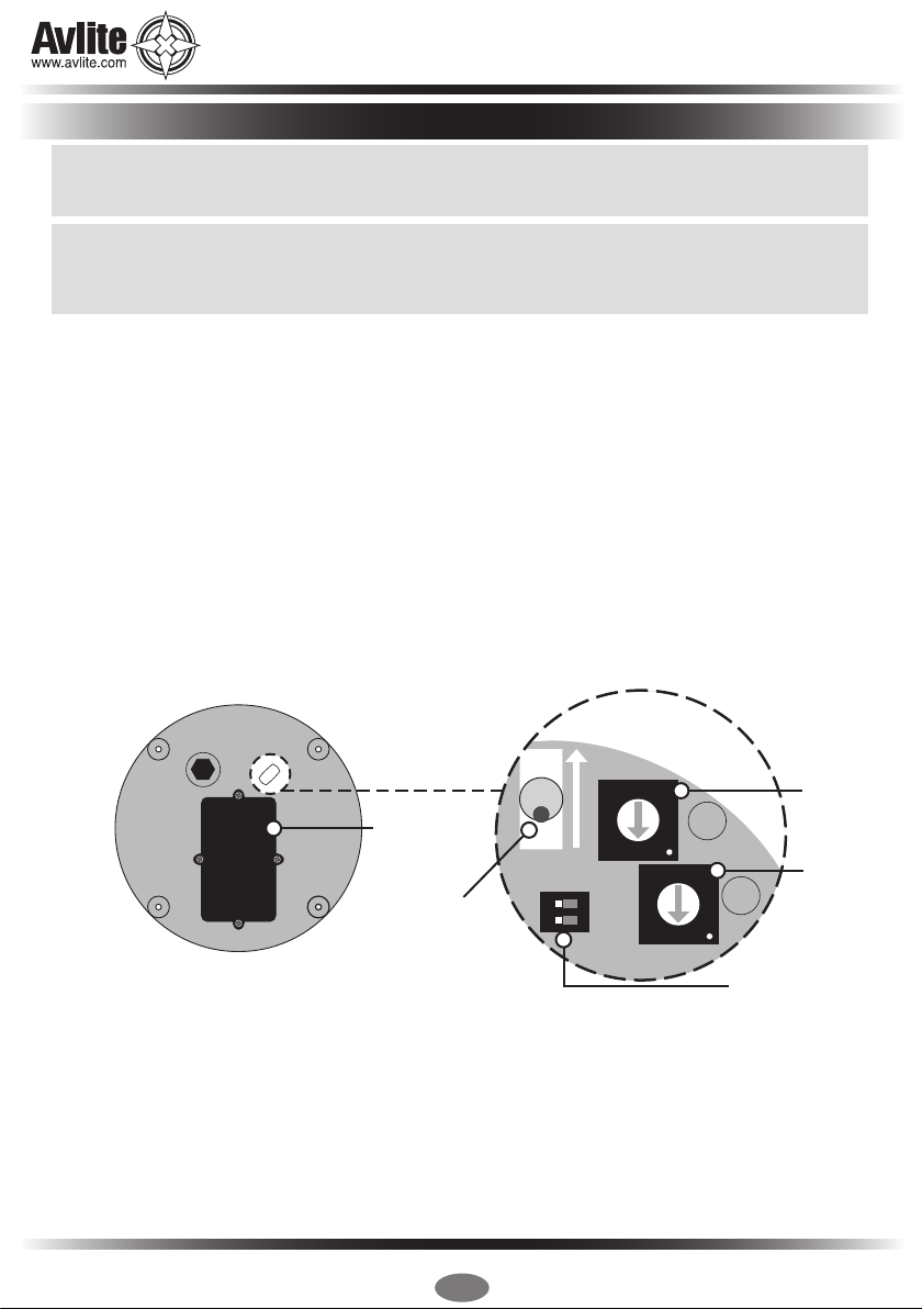
Available Flash Characteristics >250 including steady-on (user-
adjustable)
>250 including steady-on (user-
adjustable)
Intensity Adjustments Low: 25% Medium: 50% High: 100% Low: 25% Medium: 50% High: 100%
LED Life Expectancy (hours) >100,000 >100,000
Electrical Characteristics
Operating Voltage (V) 3.6 3.6
• Specications subject to change or variation without notice
* Subject to standard terms and conditions
† Intensity setting subject to solar availability
Power (W) @ 100% intensity: 0.2W @ 100% intensity: 0.2W
Temperature Range -40 to 80°C -40 to 80°C
Solar Characteristics
Solar Module Type Multicrystalline Multicrystalline
Output (watts) 2.5 (2 x 1.25watt) 2.5 (2 x 1.25watt)
Charging Regulation Microprocessor controlled Microprocessor controlled
Power Supply
Battery Type High grade NiMH – Environmentally
friendly
High grade NiMH – Environmentally
friendly
Battery Capacity (Ah) 8 16
Nominal Voltage (V) 3.6 3.6
Autonomy (nights) Steady-on: 12 nights Steady-on: 16Ah = 24 nights
Physical Characteristics
Body Material LEXAN® Polycarbonate – UV stabilized LEXAN® Polycarbonate – UV stabilized
Lens Material LEXAN® Polycarbonate – UV stabilized LEXAN® Polycarbonate – UV stabilized
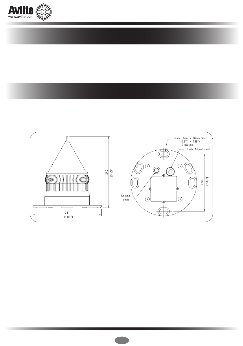
Lens Diameter (mm/inches) 140 / 5½ 140 / 5½
Lens Design External optics with interior ute design External optics with interior ute design
Mounting 6 x 17mm holes on 200mm PCD 6 x 17mm holes on 200mm PCD
Height (mm/inches) 240 / 9½ 240 / 9½
Width (mm/inches) 231 / 91/8231 / 91/8
Mass (kg/lbs) 1.1 / 23/81.1 / 23/8
Product Life Expectancy 12 years plus 12 years plus
Environmental Factors
Humidity 0 to 100%, MIL-STD-810F 0 to 100%, MIL-STD-810F
Icing 3.41kg per square cm / 48.5lbs per
square inch
3.41kg per square cm / 48.5lbs per
square inch
Wind Speed Up to 160kph / 100mph Up to 160kph / 100mph
Shock MIL-STD-202G,Test Condition G, Method
213B
MIL-STD-202G,Test Condition G, Method
213B
Vibration MIL-STD202G,Test Condition B, Method
204
MIL-STD202G,Test Condition B, Method
204
Certications
CE EN61000-6-3:2007 EN61000-6-1:2007 EN61000-6-3:2007 EN61000-6-1:2007
Quality Assurance ISO9001:2008 ISO9001:2008
Waterproof IP68 IP68
Intellectual Property
Patents US Pat. No. 6,667,582. AU Pat. No. 778,918 US Pat. No. 6,667,582. AU Pat. No. 778,918
Trademarks AVLITE® is a registered trademark of
Avlite Systems
AVLITE® is a registered trademark of
Avlite Systems
Warranty * 3 year warranty 3 year warranty
Options Available • IR LEDs
• External ON/OFF Switch
• External Battery Charging Port
• Solar Booster™
• IR LEDs
• External ON/OFF Switch
• External Battery Charging Port
• Solar Booster™

Latest products and information available at www.avlite.com
7
AV-OL-70 & AV-OL-70-HI
Solar Obstruction Light
Charging the Battery
New lights should be left in the sun for 1-2 days to ensure battery is charged before placing in
service. Please note, light will re-charge even when toggle switch is turned to ‘OFF’ position.
Preferred Installation Location
For best light performance, ensure solar modules are not covered and are in clear view of
the sky with no shadows.
Light Operation
Light is activated by ON/OFF Switch. Intensity and ash settings need to be set prior to installation.
1. Remove the marked ash adjustment bung from the base of the light and set internal toggle switch
to ‘ON’.
2. The power and range settings of the light are adjusted by setting the DIP switches inside the light.
Your light is normally set to maximum range (see ‘Selecting an Intensity/Power Setting’ section of
this manual).
3. Set rotary switches to the required ash code (see ‘Selecting a Flash Code’ section of this
manual).
4. Replace ash adjustment bung.
5. A sealed vent on the base allows air transfer without moisture intake, and should not be disturbed.
6. To test place dark cover (towel or jacket) on top of light to activate sensor, light will come on within
one minute.
7. Ensure that the unit is bolted to an even, at surface.
4
5
6
7
8
9
A
B
C
D
E
F
0
1
2
3
4
5
6
7
8
9
A
B
C
D
E
F
0
1
2
3
A
B
1 2
ON
ON
Rotary
Switch B
Rotary
Switch A
Intensity Setting
F
L
A
S
H
A
D
J
U
S
T
M
E
N
T
S
E
A
L
E
D
V
E
N
T
ON / OFF
Switch
User
Replaceable
Battery
Light
Base
Installation

Latest products and information available at www.avlite.com
8
AV-OL-70 & AV-OL-70-HI
Solar Obstruction Light
Intensity/power settings on Avlite lanterns operate via DIP switches, located near the rotary switches on
the asher unit. The intensity/power settings may be used to reduce the power consumption and intensity
of the lantern. Setting the lantern to 25% intensity will reduce the power consumption to 25% of the normal
100% setting and the range by 25%. This setting may be used to adjust the current draw of the light to
local sunlight conditions.
The following diagrams indicate intensity/power settings:-
Power Consumption Calculator
If the number of Full Sunlight hours is less than 2.5-3.0 hours, please consider reducing the intensity
(Power) or reducing the Duty Cycle.
All lights have 2 rotary switches marked A and B on the asher unit. Turning the small arrows to the
appropriate number or letter will set the code (see ‘Flash Codes’ section, of this manual). The unit may
take up to one minute to activate a new ash code. A comprehensive list of available ash codes is listed
on pages in the ‘Flash Codes’ section of this manual.
Example:
100%
1 2
ON
50%
1 2
ON
50%
1 2
ON
25%
1 2
ON Intensity
Setting
Power: mA / hour
AV-OL-70/HI
100% 54-56
50% 27-28
25% 13-14
4
5
6
7
8
9
A
B
C
D
E
F
0
1
2
3
4
5
6
7
8
9
A
B
C
D
E
F
0
1
2
3
A
B
SWITCH FLASH CODE ON OFF
A B
A 0 FL 3 S 0.3 2.7
Night Hours
(use 13.7 if
unknown)
Power
mA/hour
Duty Cycle
(e.g. 20% = 0.2)
Total power
used per night
(mA)
X X =
Selecting an Intensity/Power Setting
Selecting a Flash Code - Rotary Switches A & B
Total power
used per night
(mAh)
Solar Panel
Charge (mA)
Number of full sunlight hours
required to break even
(the amount of time it will take for the solar to
replace what the light took out overnight)
/ 279 =

Latest products and information available at www.avlite.com
9
AV-OL-70 & AV-OL-70-HI
Solar Obstruction Light
Flash Codes
AVLITE® code reference is listed by number of ashes
For the latest version of this document visit www.avlite.com,
Symbols
FL Flash followed by number Eg. FL 1 S, one ash every second
F Fixed
Q Quick ash
VQ Very quick ash
OC Occulting; greater period on than off
ISO Isophase; equal period on and off
LFL Long ash long
MO Morse code ( ) contains letter
For example, VQ (6) + LFL 10 S means 6 very quick ashes followed by a long ash, during a
10-second interval.
The amount of power your light draws through the night depends on the duty cycle, i.e. the amount of
time on as a proportion to the timing cycle. For example, 0.5 seconds on and 4.5 seconds off equals a
10% duty cycle.
It is best to operate at the lowest duty cycle appropriate to the actual needs of the application.
Please note, Avlite models will retain full autonomy in normal operating conditions with duty-cycles up to
approximately 30%. In applications whereby duty cycles exceed this limit, a reduction in light intensity is
recommended. Please contact a Avlite consultant if assistance is required.

Latest products and information available at www.avlite.com
10
SWITCH FLASH CODE ON OFF
A B
0 0 F (Steady light)
D 3 VQ 0.5 S 0.2 0.3
E 3 VQ 0.6 S 0.2 0.4
F 3 VQ 0.6 S 0.3 0.3
7 3 Q 1 S 0.2 0.8
8 3 Q 1 S 0.3 0.7
9 3 Q 1 S 0.4 0.6
A 3 Q 1 S 0.5 0.5
8 4 Q 1 S 0.8 0.2
B 3 Q 1.2 S 0.3 0.9
9 4 Q 1.2 S 0.5 0.7
C 3 Q 1.2 S 0.6 0.6
F 4 FL 1.5 S 0.2 1.3
1 0 FL 1.5 S 0.3 1.2
0 5 FL 1.5 S 0.4 1.1
0 4 FL 1.5 S 0.5 1.0
2 0 FL 2 S 0.2 1.8
3 0 FL 2 S 0.3 1.7
4 0 FL 2 S 0.4 1.6
5 0 FL 2 S 0.5 1.5
6 0 FL 2 S 0.7 1.3
7 0 FL 2 S 0.8 1.2
1 2 ISO 2 S 1.0 1.0
8 0 FL 2.5 S 0.3 2.2
9 0 FL 2.5 S 0.5 2.0
D 6 FL 2.5 S 1.0 1.5
1 5 FL 3 S 0.2 2.8
A 0 FL 3 S 0.3 2.7
2 5 FL 3 S 0.4 2.6
B 0 FL 3 S 0.5 2.5
3 5 FL 3 S 0.6 2.4
C 0 FL 3 S 0.7 2.3
D 0 FL 3 S 1.0 2.0
2 2 ISO 3 S 1.5 1.5
5 4 OC 3 S 2.0 1.0
E 2 OC 3 S 2.5 0.5
4 6 OC 3.5 S 2.5 1.0
4 5 FL 4 S 0.2 3.8
5 5 FL 4 S 0.3 3.7
E 0 FL 4 S 0.4 3.6
F 0 FL 4 S 0.5 3.5
6 5 FL 4 S 0.6 3.4
0 1 FL 4 S 0.8 3.2
1 1 FL 4 S 1.0 3.0
2 1 FL 4 S 1.5 2.5
3 2 ISO 4 S 2.0 2.0
3 6 OC 4 S 2.5 1.5
F 2 OC 4 S 3.0 1.0
3 1 FL 4.3 S 1.3 3.0
8 5 FL 5 S 0.2 4.8
4 1 FL 5 S 0.3 4.7
5 1 FL 5 S 0.5 4.5
9 5 FL 5 S 0.9 4.1
6 1 FL 5 S 1.0 4.0
SWITCH FLASH CODE ON OFF
A B
7 1 FL 5 S 1.5 3.5
4 2 ISO 5 S 2.5 2.5
8 2 LFL 5 S 2.0 3.0
0 3 OC 5 S 3.0 2.0
1 3 OC 5 S 4.0 1.0
2 3 OC 5 S 4.5 0.5
C 6 FL 6 S 0.2 5.8
B 5 FL 6 S 0.3 5.7
C 5 FL 6 S 0.4 5.6
8 1 FL 6 S 0.5 5.5
9 1 FL 6 S 0.6 5.4
A 1 FL 6 S 1.0 5.0
7 5 FL 6 S 1.2 4.8
B 1 FL 6 S 1.5 4.5
5 2 ISO 6 S 3.0 3.0
9 2 LFL 6 S 2.0 4.0
6 4 OC 6 S 4.0 2.0
3 3 OC 6 S 4.5 1.5
4 3 OC 6 S 5.0 1.0
A 4 FL 7 S 1.0 6.0
9 6 FL 7 S 2.0 5.0
5 6 OC 7 S 4.5 2.5
D 5 FL 7.5 S 0.5 7.0
C 1 FL 7.5 S 0.8 6.7
E 5 FL 8 S 0.5 7.5
B 4 FL 8 S 1.0 7.0
6 2 ISO 8 S 4.0 4.0
A 2 LFL 8 S 2.0 6.0
6 6 OC 8 S 5.0 3.0
B 2 LFL 8 S 3.0 5.0
F 5 FL 9 S 0.9 8.1
C 4 FL 9 S 1.0 8.0
7 6 OC 9 S 6.0 3.0
0 6 FL 10 S 0.2 9.8
1 6 FL 10 S 0.3 9.7
D 1 FL 10 S 0.5 9.5
2 6 FL 10 S 0.8 9.2
E 1 FL 10 S 1.0 9.0
1 4 FL 10 S 1.5 8.5
C 2 LFL 10 S 2.0 8.0
D 2 LFL 10 S 3.0 7.0
7 2 ISO 10 S 5.0 5.0
2 4 LFL 10 S 4.0 6.0
8 6 OC 10 S 6.0 4.0
5 3 OC 10 S 7.0 3.0
6 3 OC 10 S 7.5 2.5
F 1 FL 12 S 1.2 10.8
D 4 FL 12 S 2.5 9.5
3 4 LFL 12 S 2.0 10.0
0 2 FL 15 S 1.0 14.0
4 4 LFL 15 S 4.0 11.0
7 4 OC 15 S 10 5.0
A 6 LFL 20 S 2.0 18.0
E 4 FL 26 S 1.0 25.0

Latest products and information available at www.avlite.com
11
AV-OL-70 & AV-OL-70-HI
Solar Obstruction Light
SWITCH FLASH CODE ON OFF ON OFF
A B
0 A FL (2) 4 S 0.5 1.0 0.5 2.0
E B VQ (2) 4 S 0.2 1.0 0.2 2.6
1 A FL (2) 4.5 S 0.3 1.0 0.3 2.9
2 A FL (2) 4.5 S 0.4 1.0 0.4 2.7
3 A FL (2) 4.5 S 0.5 1.0 0.5 2.5
F 9 FL (2) 5 S 0.2 0.8 0.2 3.8
2 C FL (2) 5 S 0.2 1.2 0.2 3.4
4 A FL (2) 5 S 0.4 0.6 0.4 3.6
0 7 FL (2) 5 S 0.5 1.0 0.5 3.0
1 7 FL (2) 5 S 1.0 1.0 1.0 2.0
9 B Q (2) 5 S 0.3 0.7 0.3 3.7
2 9 Q (2) 5 S 0.5 0.5 0.5 3.5
5 A FL (2) 5.5 S 0.4 1.4 0.4 3.3
7 8 FL (2) 6 S 0.3 0.6 1.0 4.1
A A FL (2) 6 S 0.3 0.9 0.3 4.5
6 A FL (2) 6 S 0.3 1.0 0.3 4.4
7 A FL (2) 6 S 0.4 1.0 0.4 4.2
9 9 FL (2) 6 S 0.5 1.0 0.5 4.0
2 8 FL (2) 6 S 0.8 1.2 0.8 3.2
3 7 FL (2) 6 S 1.0 1.0 1.0 3.0
3 9 Q (2) 6 S 0.3 0.7 0.3 4.7
A 9 FL (2) 7 S 1.0 1.0 1.0 4.0
7 B FL (2) 8 S 0.4 0.6 2.0 5.0
8 A FL (2) 8 S 0.4 1.0 0.4 6.2
4 7 FL (2) 8 S 0.5 1.0 0.5 6.0
8 8 FL (2) 8 S 0.8 1.2 2.4 3.6
5 7 FL (2) 8 S 1.0 1.0 1.0 5.0
4 C OC (2) 8 S 3.0 2.0 1.0 2.0
5 C OC (2) 8 S 5.0 1.0 1.0 1.0
F B VQ (2) 8 S 0.2 1.0 0.2 6.6
9 A FL (2) 10 S 0.4 1.6 0.4 7.6
6 7 FL (2) 10 S 0.5 1.0 0.5 8.0
7 7 FL (2) 10 S 0.5 1.5 0.5 7.5
6 9 FL (2) 10 S 0.5 2.0 0.5 7.0
8 7 FL (2) 10 S 0.8 1.2 0.8 7.2
B 9 FL (2) 10 S 1.0 1.0 1.0 7.0
9 7 FL (2) 10 S 1.0 1.5 1.0 6.5
4 9 Q (2) 10 S 0.6 0.4 0.6 8.4
B A FL (2) 12 S 0.4 1.0 0.4 10.2
C 9 FL (2) 12 S 0.5 1.0 0.5 10.0
D 9 FL (2) 12 S 1.5 2.0 1.5 7.0
A 8 FL (2) 15 S 0.5 1.5 2.0 11.0
A 7 FL (2) 15 S 1.0 2.0 1.0 11.0
8 B Q (2) 15 S 0.2 0.8 0.2 13.8
C A FL (2) 20 S 1.0 3.0 1.0 15.0
D A FL (2) 25 S 1.0 1.0 1.0 22.0
SWITCH FLASH CODE ON OFF ON OFF ON OFF
A B
7 9 Q (3) 5 S 0.5 0.5 0.5 0.5 0.5 2.5
5 9 VQ (3) 5 S 0.2 0.3 0.2 0.3 0.2 3.8
0 C VQ (3) 5 S 0.3 0.2 0.3 0.2 0.3 3.7
E 9 VQ (3) 5 S 0.3 0.3 0.3 0.3 0.3 3.5
3 C FL (3) 6 S 0.5 1.0 0.5 1.0 0.5 2.5
2 B FL (2+1) 6 S 0.3 0.4 0.3 1.2 0.3 3.5

Latest products and information available at www.avlite.com
12
AV-OL-70 & AV-OL-70-HI
Solar Obstruction Light
SWITCH FLASH CODE ON OFF ON OFF ON OFF
A B
A B Q (3) 6 S 0.3 0.7 0.3 0.7 0.3 3.7
F A FL (3) 8 S 0.5 1.0 0.5 1.0 0.5 4.5
0 B FL (3) 9 S 0.3 1.0 0.3 1.0 0.3 6.1
B 7 FL (3) 9 S 0.8 1.2 0.8 1.2 0.8 4.2
B 8 FL (3) 10 S 0.3 0.7 0.3 0.7 0.9 7.1
C 8 FL (3) 10 S 0.4 0.6 0.4 0.6 1.2 6.8
C B FL (3) 10 S 0.5 0.5 0.5 0.5 0.5 7.5
C 7 FL (3) 10 S 0.5 1.5 0.5 1.5 0.5 5.5
D B FL (3) 10 S 0.6 0.6 0.6 0.6 0.6 7.0
D 7 FL (3) 10 S 1.0 1.0 1.0 1.0 1.0 5.0
3 8 FL (2+1) 10 S 0.5 0.7 0.5 2.1 0.5 5.7
8 9 OC (3) 10 S 5.0 1.0 1.0 1.0 1.0 1.0
B B Q (3) 10 S 0.3 0.7 0.3 0.7 0.3 7.7
D 8 FL (2 + 1) 10 S 0.5 0.5 0.5 0.5 1.5 6.5
1 B FL (3) 12 S 0.5 1.5 0.5 1.5 0.5 7.5
E A FL (3) 12 S 0.5 2.0 0.5 2.0 0.5 6.5
E 7 FL (3) 12 S 0.8 1.2 0.8 1.2 0.8 7.2
B 6 FL (3) 12 S 1.0 1.0 1.0 3.0 1.0 5.0
4 8 FL (2+1) 12 S 0.8 1.2 0.8 2.4 0.8 6.0
5 8 FL (2+1) 12 S 1.0 1.0 1.0 4.0 1.0 4.0
1 8 FL (2+1) 13.5 S 1.0 1.0 1.0 4.0 1.0 5.5
F 7 FL (3) 15 S 0.3 1.7 0.3 1.7 0.3 10.7
9 D FL (3) 15 S 0.4 1.0 0.4 1.0 0.4 11.8
0 8 FL (3) 15 S 0.5 1.5 0.5 1.5 0.5 10.5
F 8 FL (2+1) 15 S 0.6 0.3 0.6 0.3 1.4 11.8
0 9 FL (2+1) 15 S 0.7 0.5 0.7 0.5 1.9 10.7
1 9 FL (2+1) 15 S 0.7 0.7 0.7 0.7 2.1 10.1
6 8 FL (2+1) 15 S 1.0 2.0 1.0 5.0 1.0 5.0
1 C VQ (3) 15 S 0.1 0.5 0.1 0.5 0.1 13.7
4 B FL (3) 20 S 0.5 3.0 0.5 3.0 0.5 12.5
3 B FL (3) 20 S 0.5 1.5 0.5 1.5 0.5 15.5
5 B FL (3) 20 S 0.8 1.2 0.8 1.2 0.8 15.2
6 B FL (3) 20 S 1.0 1.0 1.0 1.0 1.0 15.0
SWITCH FLASH CODE ON OFF ON OFF ON OFF ON OFF
A B
B F VQ (4) 4 S 0.3 0.3 0.3 0.3 0.3 0.3 0.3 2.3
B D Q (4) 6 S 0.3 0.7 0.3 0.7 0.3 0.7 0.3 2.7
8 D Q (4) 6 S 0.4 0.6 0.4 0.6 0.4 0.6 0.4 2.6
1 D FL (4) 10 S 0.5 1.0 0.5 1.0 0.5 1.0 0.5 5.0
2 D FL (4) 10 S 0.8 1.2 0.8 1.2 0.8 1.2 0.8 3.2
F E Q (4) 10 S 0.3 0.7 0.3 0.7 0.3 0.7 0.3 6.7
B E FL (4) 12 S 0.3 1.7 0.3 1.7 0.3 1.7 0.3 5.7
4 F FL (4) 12 S 0.5 0.5 0.5 0.5 0.5 0.5 0.5 8.5
C E FL (4) 12 S 0.5 1.5 0.5 1.5 0.5 1.5 0.5 5.5
3 D FL (4) 12 S 0.8 1.2 0.8 1.2 0.8 1.2 0.8 5.2
A D Q (4) 12 S 0.3 0.7 0.3 0.7 0.3 0.7 0.3 8.7
4 D FL (4) 15 S 0.5 1.5 0.5 1.5 0.5 1.5 0.5 8.5
8 E FL (4) 15 S 1.0 1.0 1.0 1.0 1.0 1.0 1.0 8.0
7 D FL (4) 15 S 1.5 0.5 0.5 0.5 0.5 0.5 0.5 10.5
D E FL (4) 16 S 0.5 1.5 0.5 1.5 0.5 1.5 0.5 9.5
C D FL (4) 20 S 0.3 3.0 0.3 3.0 0.3 3.0 0.3 9.8
5 D FL (4) 20 S 0.5 1.5 0.5 1.5 0.5 1.5 0.5 13.5
0 D FL (4) 20 S 0.5 1.5 0.5 1.5 0.5 4.5 0.5 10.5
3 F FL (4) 20 S 1.5 1.5 1.5 1.5 1.5 1.5 1.5 9.5
0 F Q (4) 20 S 0.5 0.5 0.5 0.5 0.5 0.5 0.5 16.5
E E Q (4) 28 S 0.5 0.5 0.5 0.5 0.5 0.5 0.5 24.5
6 F FL (4) 30 S 0.5 0.5 0.5 0.5 0.5 0.5 0.5 26.5

Latest products and information available at www.avlite.com
13
AV-OL-70 & AV-OL-70-HI
Solar Obstruction Light
SWITCH FLASH CODE ON OFF ON OFF ON OFF ON OFF ON OFF ON OFF ON OFF ON OFF ON OFF
A B
4 E VQ (9) 10 S 0.2 0.3 0.2 0.3 0.2 0.3 0.2 0.3 0.2 0.3 0.2 0.3 0.2 0.3 0.2 0.3 0.2 5.8
5 E VQ (9) 10 S 0.3 0.3 0.3 0.3 0.3 0.3 0.3 0.3 0.3 0.3 0.3 0.3 0.3 0.3 0.3 0.3 0.3 4.9
1 F Q (9) 15 S 0.2 0.8 0.2 0.8 0.2 0.8 0.2 0.8 0.2 0.8 0.2 0.8 0.2 0.8 0.2 0.8 0.2 6.8
0 E Q (9) 15 S 0.3 0.7 0.3 0.7 0.3 0.7 0.3 0.7 0.3 0.7 0.3 0.7 0.3 0.7 0.3 0.7 0.3 6.7
1 E Q (9) 15 S 0.6 0.6 0.6 0.6 0.6 0.6 0.6 0.6 0.6 0.6 0.6 0.6 0.6 0.6 0.6 0.6 0.6 4.8
SWITCH FLASH CODE ON OFF ON OFF ON OFF ON OFF
A B
MORSE CODE ( ) INDICATES LETTER
78MO (A) 6 S 0.3 0.6 1.0 4.1
7 B MO (A) 8 S 0.4 0.6 2.0 5.0
88MO (A) 8 S 0.8 1.2 2.4 3.6
B 8 MO (U) 10 S 0.3 0.7 0.3 0.7 0.9 7.1
C 8 MO (U) 10 S 0.4 0.6 0.4 0.6 1.2 6.8
D 8 MO (U) 10 S 0.5 0.5 0.5 0.5 1.5 6.5
98MO (A) 10 S 0.5 0.5 1.5 7.5
89MO (D) 10 S 5.0 1.0 1.0 1.0 1.0 1.0
A 8 MO (A) 15 S 0.5 1.5 2.0 11.0
F 8 MO (U) 15 S 0.6 0.3 0.6 0.3 1.4 11.8
09MO (U) 15 S 0.7 0.5 0.7 0.5 1.9 10.7
19MO (U) 15 S 0.7 0.7 0.7 0.7 2.1 10.1
7 D MO (B) 15 S 1.5 0.5 0.5 0.5 0.5 0.5 0.5 10.5
SWITCH FLASH CODE ON OFF ON OFF ON OFF ON OFF ON OFF
A B
D D Q (5) 7 S 0.3 0.7 0.3 0.7 0.3 0.7 0.3 0.7 0.3 2.7
E D Q (5) 10 S 0.3 0.7 0.3 0.7 0.3 0.7 0.3 0.7 0.3 5.7
E 8 FL (5) 12 S 0.5 1.5 0.5 1.5 0.5 1.5 0.5 1.5 0.5 3.5
5 F FL (5) 20 S 0.5 0.5 0.5 0.5 0.5 0.5 0.5 0.5 0.5 15.5
9 F FL (5) 20 S 0.8 1.2 0.8 1.2 0.8 1.2 0.8 1.2 0.8 11.2
9 E FL (5) 20 S 1.0 1.0 1.0 1.0 1.0 1.0 1.0 1.0 1.0 11.0
SWITCH FLASH CODE ON OFF ON OFF ON OFF ON OFF ON OFF ON OFF
A B
F D Q (6) 10 S 0.3 0.7 0.3 0.7 0.3 0.7 0.3 0.7 0.3 0.7 0.3 4.7
A F FL (6) 15 S 0.3 0.7 0.3 0.7 0.3 0.7 0.3 0.7 0.3 0.7 0.3 9.7
7 F FL (6) 15 S 0.5 1.0 0.5 1.0 0.5 1.0 0.5 1.0 0.5 1.0 0.5 7.0
SWITCH FLASH CODE ON OFF ON OFF ON OFF ON OFF ON OFF ON OFF ON OFF
A B
6 E VQ (6) + LFL 10 S 0.2 0.3 0.2 0.3 0.2 0.3 0.2 0.3 0.2 0.3 0.2 0.3 2.0 5.0
7 E VQ (6) + LFL 10 S 0.3 0.3 0.3 0.3 0.3 0.3 0.3 0.3 0.3 0.3 0.3 0.3 2.0 4.4
2 F Q (6) + LFL 15 S 0.2 0.8 0.2 0.8 0.2 0.8 0.2 0.8 0.2 0.8 0.2 0.8 2.0 7.0
2 E Q (6) + LFL 15 S 0.3 0.7 0.3 0.7 0.3 0.7 0.3 0.7 0.3 0.7 0.3 0.7 2.0 7.0
3 E Q (6) + LFL 15 S 0.6 0.6 0.6 0.6 0.6 0.6 0.6 0.6 0.6 0.6 0.6 0.6 2.0 5.8
8 F VQ (6) + LFL 15 S 0.3 0.3 0.3 0.3 0.3 0.3 0.3 0.3 0.3 0.3 0.3 0.3 2.0 9.4

Latest products and information available at www.avlite.com
14
AV-OL-70 & AV-OL-70-HI
Solar Obstruction Light
Installing the Light Assembly to a Plate
The completed AV-OL-70 mount plate assembly is to be mounted on the plate (Fig 3)
a. Fit the AV-OL-70 light on the top of the mounting plate. Insert bolts through the four holes in
the mount, entering from the bottom. Install a penny washer and a Nylock nut on each bolt and tighten.
b. Fit the boss of the mount plate to desired pole installation. Using a 6mm Allen key, tighten the
socket head cap screw against the pole.
1
2
5
3
4
6
7
9
8
Figure 3 Plate Mount Installation

Latest products and information available at www.avlite.com
15
AV-OL-70 & AV-OL-70-HI
Solar Obstruction Light
Maintenance and Servicing
Designed to be maintenance free, the AV-OL-70 / AV-OL-70-HI requires minimal attention, though the
following maintenance and servicing information is provided to help ensure the life of your Avlite product.
1. Cleaning Solar Panels - occasional cleaning of the solar panels may be required. Using a cloth and
warm soapy water, wipe off any foreign matter before rinsing the panels with fresh water.
2. Battery Check - inspection of batteries should be performed every three years (minimum) to ensure
that the charger, battery and ancillary electronics are functioning correctly. Using a voltage meter,
check that the battery voltage is at least 3.6 volts under 100mA load, and ensure all terminals are
clear of foreign matter.
Replacing the battery- Don’t throw the unit out!!
The AV-OL-70 / AV-OL-70-HI lights are the only compact aviation light with a double sealed battery
compartment. This provides the user with the ability to change the battery after years of operation.
1. Remove the marked ash adjustment bung from the base of the light and set internal toggle switch
to ‘OFF’.
2. Unscrew small screws to remove battery plate.
3. Remove battery from AV-OL-70 / AV-OL-70-HI case and unscrew positive and negative leads.
4. Discard old battery in a safe manner.
5. Reattach positive and negative leads to new battery and then place back into case.
6. Reattach battery plate and switch light ‘ON’ via internal switch. Close the bung.
7. To test place dark cover (towel or jacket) on top of light to activate sensor, light will come on.
Care must be taken to observe the polarity of the battery before the leads are re-connected, and
ensure the replacement battery is correctly tted. Always discard old batteries in a safe manner.
Long Term Storage Instructions
If the AV-OL-70 / AV-OL-70-HI is to be placed in storage for an extended period, being more than 5
months, please follow the below steps.
1. The 3.6V NiMH Battery must be stored in a fully charged condition.
2. Remove the Flash Adjustment plug and turn the ON/OFF switch to the OFF position.
3. Remove the battery cover and disconnect the Positive (+) Terminal.
4. Fold the Terminal away from the Negative Battery Terminal.
5. Replace the Battery Cover
6. Replace the Flash Adjustment Plug.
All batteries will discharge over time and the rate of discharge is dependent on temperature. If the light is
being stored in temperatures greater than 40°C the battery will discharge faster.
Please check battery every 3-6 months and recharge if necessary.
Recharging the Battery
1. Remove the Battery Cover and connect the Positive Terminal.
2. Remove the Flash Adjustment Plug and turn the ON/OFF switch to the ON position.
3. Reconnect the Light Head and place unit in the sun for 2-4 days
Or
Reconnect Light Head and place in front of a halogen lamp for 2-3 days. (Do not place the halogen light
too close to the solar panel or the panel may be overheated)
Check the battery voltage regularly to make sure the unit is charging correctly.
After the battery has been recharged, switch the light OFF.

Latest products and information available at www.avlite.com
16
AV-OL-70 & AV-OL-70-HI
Solar Obstruction Light
Trouble Shooting
Problem Remedy
Light will not activate. • Ensure internal toggle switch is set to the ‘ON position.
• Ensure light is in darkness.
• Wait at least 60 seconds for the program to initialise in darkness.
• Ensure switch setting is on a valid code (See ‘Flash Codes’ section of
this manual).
• Ensure battery terminals are properly connected.
• Ensure battery voltage is above 3.6volts.
Timing codes will not change. • Turn rotary switches several times to ensure contacts are clear.
Light will not operate for the
entire night.
• Expose light to direct sunlight and monitor operation for several days.
Avlite products typically require 1.5 hours of direct sunlight per day to
retain full autonomy. From a discharged state, the light may require
several days of operational conditions to ‘cycle’ up to full autonomy.
• Reducing the light output intensity or duty cycle (ash code) will reduce
current draw on the battery.
• Ensure solar module is clean and not covered by shading during the day.
Lights are constantly on
during the day.
• Ensure the ash code is not set to F F. This ash code is for testing
purposes only and will be steady on for 24 hours a day.
Radio controlled models of the AV-OL-70 / AV-OL-70-HI are tted with a red Status LED. This is found
near the Flash Code Switches. It helps determine a fault with the unit depending on the ash rate of
the Status LED.
Flash Rate Mode Status Condition
On (sec.) OFF
Steady Off Off Normal Normal running condition in daylight.
1/10 1 On Normal Lantern is not synchronised to other lanterns.
1 1 On Normal Lantern is synchronised to surrounding lanterns.
Steady On Off Flat Battery Battery is at.
1/10 1/10 On Low Battery Battery is low.
1 2/10 On Factory Set. Unit is in factory setup mode (FF). Change ash code.

Latest products and information available at www.avlite.com
17
AV-OL-70 & AV-OL-70-HI
Solar Obstruction Light
Notes

Latest products and information available at www.avlite.com
18
AV-OL-70 & AV-OL-70-HI
Solar Obstruction Light
Activating the Warranty
Upon purchase, the Avlite Systems warranty must be activated for recognition of future claims. To do
this you need to register on-line. Please complete the Online Registration Form at:
www.avlite.com
Avlite Systems will repair or replace your lantern in the event of electronic failure for a period
of up to three years from the date of purchase.
Avlite Systems will repair or replace any ancillary or accessory products in the event of failure
for a period of up to one year from the date of purchase, as per the terms & conditions below.
The unit must be returned to Avlite freight prepaid.
Warranty Terms
1. Avlite Systems warrants that any Avlite aviation products tted with telemetry equipment including
but not limited to AIS, GSM, GPS or RF (“Telemetry Products”) will be free from defective materials
and workmanship under normal and intended use, subject to the conditions hereinafter set forth,
for a period of twelve (12) months from the date of purchase by the original purchaser.
2. Avlite Systems warrants that any rotationally-moulded products (“Roto-Moulded Products”) and
accessory products (“Accessory Products”) will be free from defective materials and workmanship
under normal and intended use, subject to the conditions hereinafter set forth, for a period of
twelve (12) months from the date of purchase by the original purchaser.
3. Avlite Systems warrants that any Avlite aviation products other than the Telemetry Products, Roto-
Moulded Products and Accessory Products (“Avlite Products”) will be free from defective materials
and workmanship under normal and intended use, subject to the conditions hereinafter set forth,
for a period of three (3) years from the date of purchase by the original purchaser.
4. Avlite Systems warrants that any Avlite obstruction products other than the Telemetry Products,
Roto-Moulded Products and Accessory Products (“Avlite Products”) will be free from defective
materials and workmanship under normal and intended use, subject to the conditions hereinafter
set forth, for a period of ve (5) years from the date of purchase by the original purchaser.
5. Avlite Systems will repair or replace, at Avlite’s sole discretion, any Telemetry Products, Roto-
Moulded Products, Accessory Products or Avlite Products found to be defective in material and
workmanship in the relevant warranty period so long as the Warranty Conditions (set out below)
are satised.
6. If any Telemetry Products or Avlite Products are tted with a rechargeable battery, Avlite Systems
warrants the battery will be free from defect for a period of one (1) year when used within original
manufacturer’s specications and instructions.
Warranty Conditions
This Warranty is subject to the following conditions and limitations;
1. The warranty is applicable to lanterns manufactured from 1/1/2009.
2. The warranty is void and inapplicable if:
a. the product has been used or handled other than in accordance with the instructions in the
owner’s manual and any other information or instructions provided to the customer by Avlite;
b. the product has been deliberately abused, or misused, damaged by accident or neglect or in being
transported; or
c. the defect is due to the product being repaired or tampered with by anyone other than Avlite or
authorised Avlite repair personnel.
3. The customer must give Avlite Systems notice of any defect with the product within 30 days of the
customer becoming aware of the defect.
4. Rechargeable batteries have a limited number of charge cycles and may eventually need
to be replaced. Typical battery replacement period is 3-4 years. Long term exposure to high
temperatures will shorten the battery life. Batteries used or stored in a manner inconsistent with
Avlite Light Warranty V1.3

Latest products and information available at www.avlite.com
19
AV-OL-70 & AV-OL-70-HI
Solar Obstruction Light
the manufacturer’s specications and instructions shall not be covered by this warranty.
5. No modications to the original specications determined by Avlite shall be made without written
approval of Avlite Systems.
6. Avlite lights can be tted with 3rd party power supplies and accessories but are covered by the 3rd
party warranty terms and conditions.
7. The product must be packed and returned to Avlite Systems by the customer at his or her
sole expense. Avlite Systems will pay return freight of its choice. A returned product must be
accompanied by a written description of the defect and a photocopy of the original purchase
receipt. This receipt must clearly list model and serial number, the date of purchase, the name and
address of the purchaser and authorised dealer and the price paid by the purchaser. On receipt
of the product, Avlite Systems will assess the product and advise the customer as to whether the
claimed defect is covered by this warranty.
8. Avlite Systems reserves the right to modify the design of any product without obligation to
purchasers of previously manufactured products and to change the prices or specications of any
product without notice or obligation to any person.
9. Input voltage shall not exceed those recommended for the product.
10. Warranty does not cover damage caused by the incorrect replacement of battery in solar lantern
models.
11. This warranty does not cover any damage or defect caused to any product as a result of water
ooding or any other acts of nature.
12. There are no representations or warranties of any kind by Avlite or any other person who is an
agent, employee, or other representative or afliate of Avlite, express or implied, with respect to
condition of performance of any product, their merchantability, or tness for a particular purpose, or
with respect to any other matter relating to any products.
Limitation of Liability
To the extent permitted by acts and regulations applicable in the country of manufacture, the liability
of Avlite Systems under this Warranty will be, at the option of Avlite Systems, limited to either the
replacement or repair of any defective product covered by this Warranty. Avlite Systems will not be
liable to Buyer for consequential damages resulting from any defect or deciencies in accepted items.
Limited to Original Purchaser
This Warranty is for the sole benet of the original purchaser of the covered product and shall not
extend to any subsequent purchaser of the product.
Miscellaneous
Apart from the specic warranties provided under this warranty, all other express or implied warranties
relating to the above product is hereby excluded to the fullest extent allowable under law. The warranty
does not extend to any lost prots, loss of good will or any indirect, incidental or consequential costs or
damages or losses incurred by the purchaser as a result of any defect with the covered product.
Warrantor
Avlite Systems has authorised distribution in many countries of the world. In each country, the
authorised importing distributor has accepted the responsibility for warranty of products sold by
distributor. Warranty service should normally be obtained from the importing distributor from whom
you purchased your product. In the event of service required beyond the capability of the importer,
Avlite Systems will full the conditions of the warranty. Such product must be returned at the owner’s
expense to the Avlite Systems factory, together with a photocopy of the bill of sale for that product, a
detailed description of the problem, and any information necessary for return shipment.
Information in this manual is subject to change without notice and does not represent a commitment on the part of the vendor.
Sealite products are subject to certain Australian and worldwide patent applications.

AV-OL-70 & AV-OL-70-HI
Solar Obstruction Light
Solar Aviation Lighting
Obstruction Lighting
Typical Applications
• Temporary & permanent
aireld lighting
• Remote, emergency &
defence aireld lighting
• Barricade, hazard &
perimeter lighting
• Helipad lighting
• Obstruction lighting
For a complete list of product compliances
including ICAO & FAA, please contact Avlite today
Helipad Lighting
Aireld Markers
& Accessories
A subsidiary of Sealite Pty Ltd www.sealite.com
Portable Aireld Lighting
System
Other Avlite Products Available
AUSTRALIA
t: +61 (0)3 5977 6128
USA
t: +1 (603) 737 1310
UNITED KINGDOM
t: +44 (0) 1502 588026
We believe technology improves navigation™
e: info@avlite.com
This manual suits for next models
1
Table of contents
Popular Avionic Display manuals by other brands

GRT Avionics
GRT Avionics Horizon 10.1 user manual

Avidyne
Avidyne IFD440 quick reference

Dynon Avionics
Dynon Avionics SkyView HDX Pilot's user guide

Aerospace Logic
Aerospace Logic EGT-100 Series Operation and installation manual

TQ
TQ AirPlus KRT2 Series User & installation manual

Skywatch
Skywatch SKY497 pilot's guide