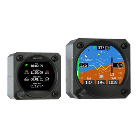
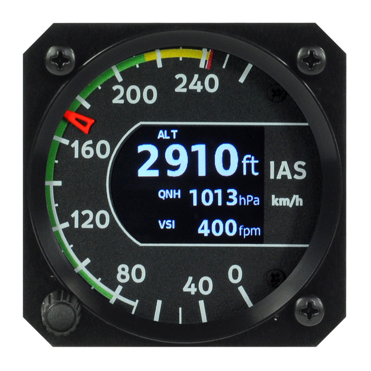
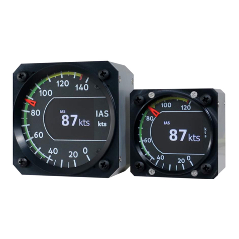
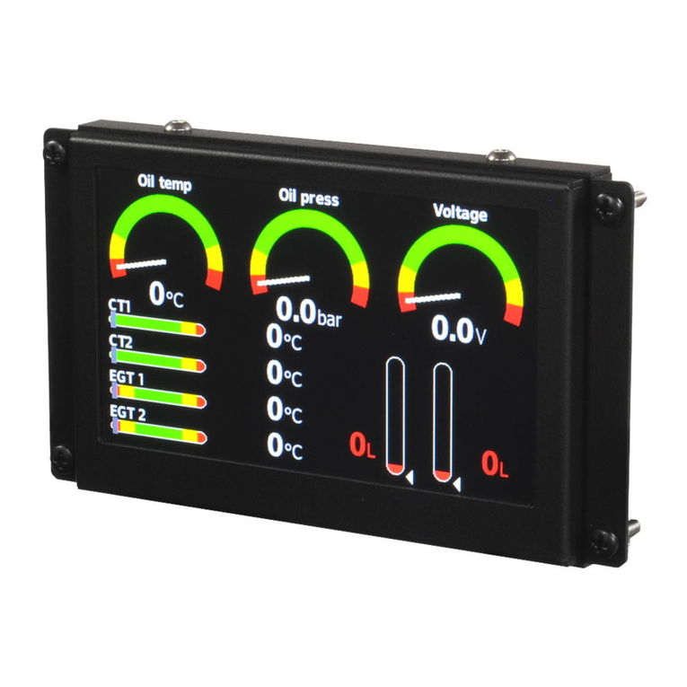
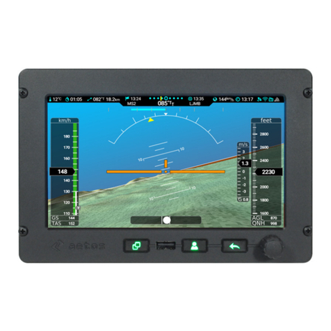
Kanardia EMSIS User manual

EMSIS
Installation and User Manual
©
Kanardia d.o.o.
November 2021
Manual Revision 3.1


Emsis — Manual
Contact Information
Publisher and producer:
Kanardia d.o.o.
Lopata 24 a
SI-3000
Slovenia
Tel: +386 40 190 951
Email: info@kanardia.eu
A lot of useful and recent information can be also found on the In-
ternet. See http://www.kanardia.eu for more details.
Copyright
This document is published under the Creative Commons, Attribu-
tion - ShareAlike 3.0 Unported licence. The license is available on
http://creativecommons.org/licenses/by-sa/3.0/legalcode web
page and a bit more human readable summary is given on http:
//creativecommons.org/licenses/by-sa/3.0/. In short, the li-
cense gives you right to copy, reproduce and modify this document
if:
you cite Kanardia d.o.o. as the author of the original work,
you distribute the resulting work only under the same or similar
license to this one.
Credits
This document was written using TeTeX (L
A
T
EX) based document
creation system using Kile running on Linux operating system. Most
3
©
Kanardia 2021

Emsis — Manual
of figures were drawn using Libre Office Draw, Inkscape and Bric-
scad applications. Photos and scanned material was processed using
Gimp. Sam2p was used to convert pictures into eps format. All
document sources are freely available on request under the license
mentioned above and can be obtained by email. Please send requests
to info@kanardia.eu.
Revision History
The following table shows the revision history of this document.
Rev. Date Description
1.0 November 2012 Initial release
2.0 February 2013 Added Installation
2.6 May 2013 Added Maps
2.12 June 2015 Added description of functions accu-
mulated in since v2.6
2.13, 2.14 July 2016 Bug fixes, red crosses on interactive
parameters, heading indicator, Lo-
Hi-NC messages
3.0 May 2020 Latex rewrite
3.1 November 2021 Figures and text updated to the lat-
est version
4
©
Kanardia 2021

Emsis — Manual
5
©
Kanardia 2021

Emsis — Manual CONTENTS
Contents
1 Introduction 9
2 General Information 9
2.1 CommandPanel .................... 10
2.2 Turning ON/OFF . . . . . . . . . . . . . . . . . . . . 11
2.3 Updating Emsis Software . . . . . . . . . . . . . . . . 11
2.3.1 Downloading Software . . . . . . . . . . . . . 12
2.3.2 Copying New Software to Emsis . . . . . . . . 12
2.3.3 Firmware Update . . . . . . . . . . . . . . . . 13
2.4 Installing New Layout . . . . . . . . . . . . . . . . . 14
2.5 Technical Specifications . . . . . . . . . . . . . . . . . 15
2.6 CANBus ........................ 15
3 Emsis PFD 18
4 Emsis EMS 19
4.1 Engine Sensors . . . . . . . . . . . . . . . . . . . . . 20
5 Screens 21
5.1 Primary Flight Display Screen . . . . . . . . . . . . . 23
5.2 Engine Monitoring Screen . . . . . . . . . . . . . . . 24
5.3 MapsScreen....................... 27
5.3.1 ZoomLevel ................... 28
5.3.2 Activation.................... 28
5.3.3 Copying ..................... 28
5.3.4 Deleting ..................... 29
5.3.5 Information . . . . . . . . . . . . . . . . . . . 30
6
©
Kanardia 2021

Emsis — Manual CONTENTS
5.3.6 Settings ..................... 30
5.4 Emsis Setup Screen . . . . . . . . . . . . . . . . . . . 31
5.4.1 Logbook..................... 33
5.4.2 Engine...................... 34
5.4.3 Min/Max Values . . . . . . . . . . . . . . . . 38
5.4.4 Tank....................... 39
5.4.5 Brightness.................... 39
5.4.6 Airspeed..................... 39
5.4.7 Units....................... 41
5.4.8 Pilots ...................... 41
5.4.9 Maps....................... 42
5.4.10 Service...................... 42
5.4.11 About ...................... 50
6 Installation 51
6.1 Installation to the Instrument Panel . . . . . . . . . . 51
6.1.1 Emsis Back Panel Connectors and Cable Clear-
ance ....................... 52
6.2 Connection to the Electrical System . . . . . . . . . . 54
6.3 Pitot-Static Connection . . . . . . . . . . . . . . . . 55
6.4 Outside Air Temperature Probe Installation . . . . . 56
6.5 Connection to the CAN Network . . . . . . . . . . . 57
6.6 Connection to the 485 Network . . . . . . . . . . . . 58
6.7 GPS Antenna Installation . . . . . . . . . . . . . . . 58
7
©
Kanardia 2021
Emsis — Manual CONTENTS
7 Tank 59
7.1 SoftwareTank...................... 59
7.2 HardwareTank ..................... 60
7.2.1 Units....................... 61
7.2.2 Setting up the Channel . . . . . . . . . . . . . 61
7.2.3 Tank Calibration in Steps . . . . . . . . . . . 62
7.2.4 Tank Calibration Using Known Shape . . . . 66
8 Limited Conditions 69
8.1 Warranty ........................ 69
8.2 TSO Information . . . . . . . . . . . . . . . . . . . . 72
8
©
Kanardia 2021

Emsis — Manual 1. Introduction
1 Introduction
First of all, we would like to thank you for purchasing our product.
The Emsis system is a set of complex electronics devices and we
strongly recommend to carefully read this manual before installing
and using the system.
Emsis is a name for a line of flight instruments which can be used as:
primary flight display (PFD),
engine monitoring system (EMS).
or both.
The introduction chapter contains some general information about
the instrument and its operation. Later chapters describe Emsis use
and reveal the details.
CAUTION: Emsis is not TSO approved as a flight instrument.
2 General Information
This chapter describes the organization of the Emsis instrument. It
teaches you about the individual buttons and their meaning. After
reading it, you will be familiar with basic operations.
9
©
Kanardia 2021

Emsis — Manual 2.1 Command Panel
2.1 Command Panel
Emsis instruments come in two physical sizes. The first one is a
standard aviation size, which is 80 mm diagonal, while the second
one is non-standard and is characterized with a 3.5” screen diagonal.
The Emsis command panel is organized according to Figure 1. It uses
six (80 mm version) or five (3.5” screen version) small push buttons
to manipulate the user interface. Additionally, it has SD card slot
for software, maps and data updates.
Figure 1: Organization of Emsis front panel. Emsis 80 mm version
(left), Emsis 3.5” screen version (right)
Here is a brief description of individual items:
1
O
The up arrow button is used to move the menu selection, to
change a value or a letter within active control or some other
screen-specific function.
10
©
Kanardia 2021

Emsis — Manual 2.2 Turning ON/OFF
2
O
The OK button confirms selection.
3
O
The down arrow button does the same as the up arrow button,
just in a reverse direction.
4
O
The power ON/OFF button is normally not used. However on
some Emsis instruments, it is used to turn the instrument
on/off. Note that 3.5” screen Emsis does not have the power
ON/OFF button.
5
O
The close button serves as the close or cancel command.
6
O
The screen selector button is used to switch between screens.
7
O
SD card slot is used for software, maps and data updates.
2.2 Turning ON/OFF
Emsis is connected to the avionics power bus, therefore the instru-
ment normally turns on as soon as the avionics is switched on and
a couple of seconds later, it is ready for the operation. This is the
default behaviour.
However, in some situations, the behaviour mentioned above is not
suitable. In this case you can order a special version1, which can be
switched on or off using the power button. Please note that a minor
hardware modification is required. This must be done in factory.
2.3 Updating Emsis Software
The Emsis software is under constant development and if you want
to keep the instrument up to date, you should update it regularly.
This section describes actions required to update the software. The
update is performed in several steps:
1Typical use of this option is in a glider.
11
©
Kanardia 2021

Emsis — Manual 2.3 Updating Emsis Software
Downloading new software.
Copying new software to Emsis.
Updating devices connected to Emsis (firware update).
2.3.1 Downloading Software
The software updates are located in the Emsis/Software section of
our web site http://www.kanardia.eu/product/emsis.
Download the update file and save it to a hard drive of your PC. The
update file name is Update.kus. Never change the name of the file.
The file must be copied onto the micro SD card, more precisely into
the base (root) folder of the card. Once the file was copied, please
make sure to use safely remove option on the PC, before you remove
the card from PC.
Emsis software versions 2.4 and earlier support only micro SD cards
with the capacity of 2GB or less. Later versions also recognise HDSD
cards with a higher capacity (up to 32 GB).
Please make sure that SD card is formatted as FAT 32 or FAT 16
file system. Other file systems will not be recognised by Emsis.
2.3.2 Copying New Software to Emsis
To copy the software from the SD card to Emsis follow these steps:
1. Insert SD card with the new software (Update.kus) into Emsis
SD card slot. The contacts on the card must face upward.
2. On Emsis 80, push and hold the down arrow (on Emsis 3.5”,
push and hold the up arrow) and turn Emsis ON. A window
similar to Figure 2 appears.
12
©
Kanardia 2021

Emsis — Manual 2.3 Updating Emsis Software
Figure 2: Boot options window
3. Use the up and down button to select the Upgrade option and
press the OK button. Update process begins. Emsis tries to
detect the Update.kus file on the SD card and if it is found, the
update progress window will be displayed. In the first step, the
file integrity is verified and in the second step the file is copied
into Emsis.
4. Once finished, Emsis will start with the new software. The very
first start after the update takes slightly longer.
The Start normally option is used if you changed your mind and
you do not want to update the instrument, while the System Reset
option is used only in emergency and should never be used in normal
operation. This option asks for special password in order to protect
it from accidental use.
2.3.3 Firmware Update
The procedure from previous section copied new software to Emsis
and it has also made a partial update, but it did not change firmware
in AD-AHRS-GPS module, Daqu or any other devices that may be
connected to Emsis.
In order to sync firmware with Emsis software, follow the next steps:
13
©
Kanardia 2021

Emsis — Manual 2.4 Installing New Layout
1. Use screen selector to switch to the Emsis Setup screen.
2. Select the Service option. Enter 314 for the password.
3. Select the Firmware update option from the list. This will
start the automatic firmware update procedure. It will update
firmware in detected devices one by one. The procedure may
take a few minutes.
4. Once finished, close all windows.
2.4 Installing New Layout
Emsis screen can be configured in many different ways, depending on
the engine, other connected devices, specific sensors, etc. The engine
limits and screen organization are stored in a layout file. Layouts are
prepared by Kanardia and sent to users when requested.
Follow the steps below in order to copy a new layout to Emsis.
1. A layout file is usually sent by e-mail to the user. Copy the file
to the micro SD card. Do not open or change the file on the
PC.
2. Make sure to use the Safe remove option on PC before remov-
ing the card from PC.
3. Insert the card into Emsis and change to the Emsis Setup
screen.
4. Select Service and enter 314 password.
5. From the list of items, select the Import layout.
6. This will list layouts/configurations found on the card. Select
the one you need, then press the OK button. This will copy the
layout from SD card and activate it.
14
©
Kanardia 2021

Emsis — Manual 2.5 Technical Specifications
7. Close all windows. Emsis will reboot with the new layout ac-
tive.
2.5 Technical Specifications
Tables 1 and 2 illustrate some general instrument specifications for
each instrument size.
2.6 CAN Bus
The Emsis system can be easily extended into a much more complex
form, shown in Figure 3. We achieved this by introducing CAN bus
for the communication between the units. The CAN bus does the
magic of the all possible known and unknown future extensions.
Figure 3: Illustration of Emsis configuration using CAN bus
Imagine the CAN bus as a kind of computer network. Just like new
computers can be easily connected to the network, we connect all
new devices to CAN. This allows introduction of secondary Emsis
unit, electronic compass (Magu), pilot command stick, etc.
15
©
Kanardia 2021

Emsis — Manual 2.6 CAN Bus
Description Value
Weight 80 PFD: 298 g
80 EMS: 230 g
Size 80 PFD: 82 x 82 x 65 mm
80 EMS: 82 x 82 x 45 mm
Operational voltage 6 V to 32 V
Current 150 mA (PFD) or 140 mA (EMS) at 12 V
85 mA at 24 V
Operating temperature -30 ∼+85 ◦C
Humidity 30 ∼90 %, non condensing
Panel hole 80 mm (3.15 inch) diameter, standard fit
Altitude range -500 m to 16000 m (-1600 to 52000 feet)
Acceleration 16 bit, 3D, dynamic range 0 to 16 g,
typical resolution 0.12 mg
Angular rate 16 bit, 3D, 250◦/s, resolution 0.009◦/s
Barometric sensor 24 bit, 10 to 1200 hPa, 20 cm resolution
Airspeed sensor 12 bit, 0 to 69 hPa, 381 km/h, 205 kt
resolution <0.1 km/h
(units before Oct 19) 0 to 50 hPa, 325 km/h, 175 kt
GPS 10 Hz, 66 channel, hot start 1 s, cold 35 s,
sensitivity -165 dBm
OAT 12 bit, range -55
°
C to 125
°
C,
0.5
°
C accuracy
QNH range 590 hPa to 1080 hPa
(17.42 to 31.89 inHg)
Communication CAN bus, 29 bit header, 500 kbit,
Kanardia protocol
Display 240 x 320 pix, 2.7”, 24 bit,
full colour, super bright
Table 1: Basic technical specifications for the 80 mm Emsis.
16
©
Kanardia 2021

Emsis — Manual 2.6 CAN Bus
Description Value
Weight 3.5 PFD: 312 g
3.5 EMS: 235 g
Size 3.5 PFD: 112 x 69 x 65 mm
3.5 EMS: 112 x 69 x 45 mm
Operational voltage 6 V to 32 V
Current 170 mA (PFD) or 130 mA (EMS) at 12 V
85 mA at 24 V
Operating temperature -30 ∼+85 ◦C
Humidity 30 ∼90 %, non condensing
Panel hole 3.5 PFD: custom fit; see 3.5 cutout scheme
Altitude range -500 m to 16000 m (-1600 to 52000 feet)
Acceleration 16 bit, 3D, dynamic range 0 to 16 g,
typical resolution 0.12 mg
Angular rate 16 bit, 3D, 250◦/s, resolution 0.009◦/s
Barometric sensor 24 bit, 10 to 1200 hPa, 20 cm resolution
Airspeed sensor 12 bit, 0 to 69 hPa, 381 km/h, 205 kt
resolution <0.1 km/h
(units before Oct 19) 0 to 50 hPa, 325 km/h, 175 kt
GPS 10 Hz, 66 channel, hot start 1 s, cold 35 s,
sensitivity -165 dBm
OAT 12 bit, range -55
°
C to 125
°
C,
0.5
°
C accuracy
QNH range 590 to 1080 hPa
(17.42 to 31.89 inHg)
Communication CAN bus, 29 bit header, 500 kbit,
Kanardia protocol
Display 240 x 320 pix, 3.5”, 24 bit,
full colour, super bright
Table 2: Basic technical specifications for the 3.5” Emsis.
17
©
Kanardia 2021
Emsis — Manual 3. Emsis PFD
3 Emsis PFD
Emsis PFD (Primary flight display) consists of electronic units which
work closely together to bring flight information onto graphical dis-
play. The system consists of the following electronic components:
Airu (AD-AHRS and GPS unit) – hereinafter referred to as
AHRS unit – is an inertial navigation unit aided by the GPS
and pressure sensors. AHRS provides attitude, position and
velocities. AHRS unit is hidden inside Emsis PFD unit.
Emsis unit – presents all relevant information that appears on
the CAN bus in a pilot friendly form on LCD screen. Most of
this manual describes how to access, read and interact with the
Emsis display.
Emsis PFD unit uses state of the art MEMS2sensors to read various
physical quantities. Since all sensors are solid state, it has no moving
parts. This means it has fewer problems with fatigue and ageing.
The following MEMS sensors are used in the Emsis PFD system:
The angular rate sensors, also known as gyros, are used in the
attitude calculation. The angular rates are integrated in time
in order to predict new attitude from the old one. We could
say that they give short-time attitude prediction. They are also
used in gravity vector calculation.
The acceleration sensors are measuring apparent gravity vec-
tor. The true gravity vector is calculated assuming coordinated
flight and readings from the other sensors (velocity and angular
rate sensors). The ball slip indicator is directly obtained from
the acceleration sensors.
2MEMS - micro-electromechanical systems, a.k.a micro machines, a.k.a micro
systems technology.
18
©
Kanardia 2021
Emsis — Manual 4. Emsis EMS
The absolute pressure sensor is used to calculate altitude and
vertical velocity (vario).
The differential pressure sensor provides indicated airspeed -
IAS. When it is coupled with the outside air temperature -
OAT sensor, it also calculates true air speed - TAS.
Assuming coordinated flight, we calculate the referencing attitude
from the gravity vector and heading. These values are then compared
with the short-term prediction of the attitude. Non-linear Kalman
filters are used to combine the short-term prediction and referencing
attitude solution into one most probable solution. This is what you
see on the attitude indicator.
In a very similar way, short-term inertial position prediction is com-
pared with the GPS position. Again, Kalman filtering is used to
obtain the final solution.
When engine monitoring unit (Daqu) is present on CAN bus, Emsis
PFD can also show relevant engine and fuel information.
When maps are enabled and licensed, Emsis PFD can also show
raster maps on graphical display. Further chapters reveal the details.
4 Emsis EMS
Emsis EMS (Engine monitoring system) consists of electronic units
which work closely together to bring engine and fuel information onto
graphical display. The system is presented in Figure 4. The system
consists of the following electronic components:
Engine monitoring unit (Daqu) is used to connect the engine,
fuel and electric sensors.
19
©
Kanardia 2021
Emsis — Manual 4.1 Engine Sensors
Emsis EMS unit presents all relevant information that appears
on the CAN bus in a pilot friendly form on LCD screen. Most
of this manual describes how to access, read and interact with
the Emsis display.
Figure 4: Illustration of Emsis EMS configuration
When AHRS unit is present on CAN bus, Emsis EMS can also show
flight information on graphical display, too.
When maps are enabled and licensed and AHRS unit is present on
CAN bus, Emsis EMS can also show raster maps on graphical display.
Further chapters reveal the details.
4.1 Engine Sensors
Engine related sensors are connected to the engine monitoring unit
Daqu. Daqu is designed to be installed on the engine side of the
firewall. This has two advantages:
20
©
Kanardia 2021
Other manuals for EMSIS
2
Table of contents
Other Kanardia Avionic Display manuals

Kanardia
Kanardia INDU 80 User manual

Kanardia
Kanardia Horis User manual

Kanardia
Kanardia Indu Variometer User manual

Kanardia
Kanardia INDU Airspee User manual

Kanardia
Kanardia Aetos User manual

Kanardia
Kanardia Digi User manual

Kanardia
Kanardia INDU COMBO User manual

Kanardia
Kanardia INDU COMBO User manual
Popular Avionic Display manuals by other brands

Skytrac
Skytrac ISAT-200 Series installation manual

Dynon
Dynon EFIS-D10A installation guide

Garmin
Garmin Cessna Caravan G1000 Line maintenance manual

NORMARC
NORMARC NM 7000 Series Installation & Commissioning Handbook

MGL Avionics
MGL Avionics Blaze FLIGHT-3 operating manual

Garmin
Garmin GTN 625 pilot's guide