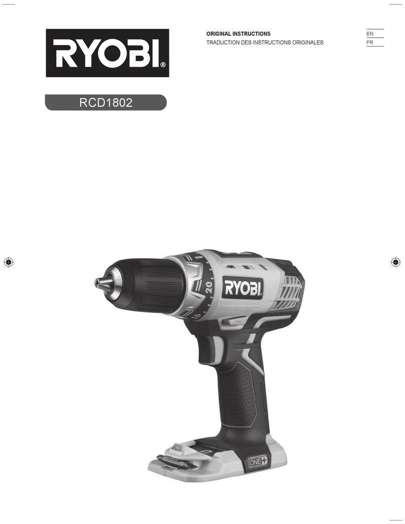
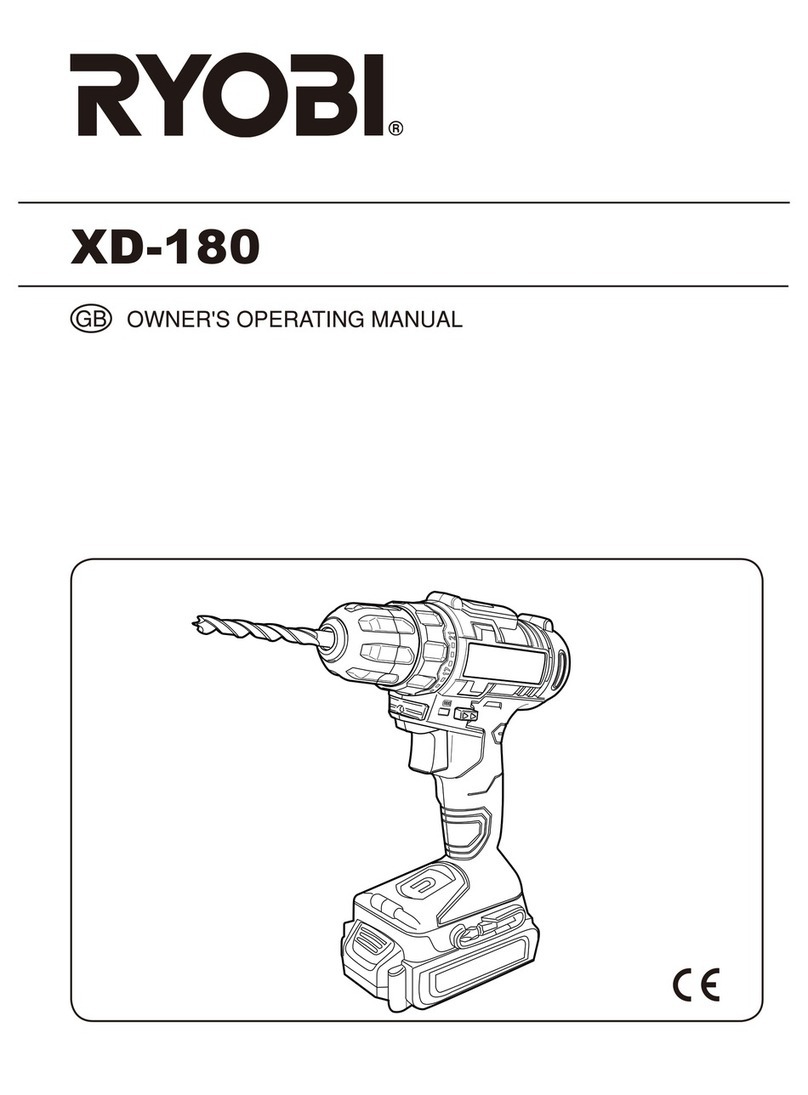
Ryobi LCDI1802 User manual

GB
18 VOLT COMPACT HAMMER DRILL DRIVER
USER’S MANUAL 1
FR
PERCEUSE/VISSEUSE COMPACTE À PERCUSSION 18 VOLTS
MANUEL D’UTILISATION 6
DE
18 VOLT KOMPAKT SCHLAGBOHRSCHRAUBER
BEDIENUNGSANLEITUNG 12
ES
ROTOMARTILLO/TALADRO/DESTORNILLADOR DE 18 VOLT
MANUAL DE UTILIZACIÓN 19
IT
TRAPANO A PERCUSSIONE COMPATTO DA 18 VOLT
MANUALE D’USO
25
NL
18 VOLT COMPACTE HAMERBOORMACHINE GEBRUIKERSHANDLEIDING 31
PT
MARTELO PERFURADOR COMPACTO DE 18 VOLTS
MANUAL DE UTILIZAÇÃO 37
DK
KOMPAKT 18 VOLT SLAGBORE-/SKRUEMASKINE
BRUGERVEJLEDNING 43
SE
18 VOLT KOMPAKT SLAGBORRMASKIN
INSTRUKTIONSBOK 49
FI
18 VOLTIN KOMPAKTI ISKUPORAKONE
KÄYTTÄJÄN KÄSIKIRJA 55
NO 18-VOLT KOMPAKT SLAGDRILL BRUKSANVISNING 60
RU КОМПАКТНАЯ УДАРНАЯ ДРЕЛЬ-ШУРУПОВЕРТ, 18 ВОЛЬТ êìäéÇéÑëíÇé èé ùäëèãìÄíÄñàà 65
PL PODRĘCZNA WIERTARKO-WKRĘTARKA UDAROWA 18 V INSTRUKCJA OBSŁUGI 71
CZ 18 VOLTOVÝ KOMPAKTNÍ PŘÍKLEPOVÝ VRTACÍ ŠROUBOVÁK NÁVOD K OBSLUZE 77
HU 18 VOLTOS KOMPAKT ÜTVEFÚRÓ-CSAVARBEHAJTÓ HASZNÁLATI ÚTMUTATÓ 83
RO CIOCAN PERFORATOR COMPACT 18 VOLŢI MANUAL DE UTILIZARE 89
LV 18 V KOMPAKTAIS PERFORATORS/SKRŪVGRIEZIS LIETOTĀJA ROKASGRĀMATA 95
LT 18 V KOMPAKTINIS PLAKTUKAS / GRĄŽTAS / SUKTUVAS NAUDOJIMO VADOVAS 101
EE KOMPAKTLÖÖKTRELL-KRUVIKEERAJA 18 VOLTI KASUTAJAJUHEND 106
HR KOMPAKTNA UDARNA BUŠILICA OD 18 V KORISNI»KI PRIRU»NIK 111
SI 18-VOLTNI KOMPAKTNI UDARNI VRTALNIK UPORABNIŠKI PRIROČNIK 116
SK 18 V KOMPAKTNÉ VŔTACIE KLADIVOSO SKRUTKOVAČOM NÁVOD NA POUŽITIE 121
GR COMPACT ΣΦΥΡΟ-ΔΡΕΠΑΝΟΚΑΤΣΑΒΙΔΟ 18 VOLT ΟΔΗΓΙΕΣ ΧΡΗΣΗΣ 127
TR 18 VOLT KOMPAKT DARBELİ MATKAP TORNAVİDA KULLANiM KILAVUZU 133
LCDI1802
GB ORIGINAL INSTRUCTIONS FR TRADUCTION DES INSTRUCTIONS ORIGINALES DE ÜBERSETZUNG DER ORIGINALANLEITUNG ES TRADUCCIÓN
DE LAS INSTRUCCIONES ORIGINALES IT TRADUZIONE DELLE ISTRUZIONI ORIGINALI NL VERTALING VAN DE ORIGINELE INSTRUCTIES PT TRADUÇÃO
DAS INSTRUÇÕES ORIGINAIS DK OVERSÆTTELSE AF DE ORIGINALE INSTRUKTIONER SE ÖVERSÄTTNING AV DE URSPRUNGLIGA INSTRUKTIONERNA
FI ALKUPERÄISTEN OHJEIDEN SUOMENNOS NO OVERSETTELSE AV DE ORIGINALE INSTRUKSJONENE RU ПЕРЕВОД ОРИГИНАЛЬНЫХ ИНСТРУКЦИЙ PL TŁUMACZENIE
INSTRUKCJI ORYGINALNEJ CZ PŘEKLAD ORIGINÁLNÍCH POKYNŮ HU AZ EREDETI ÚTMUTATÓ FORDÍTÁSA RO TRADUCEREA INSTRUCŢIUNILOR ORIGINALE LV TULKOTS NO
ORIĢINĀLĀS INSTRUKCIJAS LT ORIGINALIŲ INSTRUKCIJŲ VERTIMAS EE ORIGINAALJUHENDI TÕLGE HR PRIJEVOD ORIGINALNIH UPUTA SI PREVOD ORIGINALNIH NAVODIL
SK PREKLAD POKYNOV VORIGINÁLI GR μΕΤΑΦΡΑΣΗ ΤΩΝ ΠΡΩΤΟΤΥΠΩΝ ΟΔΗΓΙΩΝ TR ORIJINAL TALIMATLARIN TERCÜMESI

Fig. 1
Fig. 2
6
13
14
10
11
12
15
Fig. 3
17
18
16
9
7
31
33 32
12
34
7
9
8
5
6

Fig. 4
Fig. 5
Fig. 6
5
8
19
20
21
22
23
41
4
24
25
LO
HI
26 27 28
3
29
2
30
21
22 41
35
23
26 27
28
Fig. 9
Fig. 8
Fig. 7

13
636
34
35
6
I
39
38
40 37
Fig. 10
961067241-01_EU.indd A3 6/24/09 3:27:23 PM

Important!
It is essential that you read the instructions in this manual before operating this machine.
Attention !
Il est indispensable que vous lisiez les instructions contenues dans ce manuel avant la mise en service
de l’appareil.
Achtung!
Bitte lesen Sie unbedingt vor Inbetriebnahme die Hinweise dieser Bedienungsanleitung.
¡Atención!
Es imprescindible que lea las instrucciones de este manual antes de la puesta en servicio.
Attenzione!
Prima di procedere alla messa in funzione, è indispensabile leggere attentamente le istruzioni contenute
nel manuale.
Let op !
Het is van essentieel belang dat u de instructies in deze gebruiksaanwijzing leest vooraleer u dit toestel
in gebruik neemt.
Atenção!
É indispensável que leia as instruções deste manual antes de utilizar a máquina.
OBS!
Denne brugsanvisning skal læses igennem inden ibrugtagning.
Observera!
Det är nödvändigt att läsa instruktionerna i denna bruksanvisning innan användning.
Huomio!
On ehdottoman välttämätöntä lukea tässä käyttöohjeessa annetut ohjeet ennen käyttöönottoa.
Advarsel!
Det er meget viktig at du leser denne brukerveiledningen før du tar maskinen i bruk.
ÇÌËχÌËe! èee‰ Ò·ÓÍÓÈ Ë Á‡ÔÛÒÍÓÏ ËÌÒÚÛÏeÌÚ‡ ÌeÓ·ıÓ‰ËÏÓ ÔÓ˜eÒÚ¸ ËÌÒÚÛ͈ËË ËÁ ̇ÒÚÓfl˘e„Ó
ÛÍÓ‚Ó‰ÒÚ‚‡.
Uwaga!
Przed przystąpieniem do użytkowania tego urządzenia, należy koniecznie zapoznaćsięz zaleceniami
zawartymi w niniejszym podręczniku.
Důležité upozornění!
Nepoužívejte tento přístroj dříve, než si přečtete pokyny uvedené v tomto návodu.
Figyelem!
Feltétlenül fontos, hogy a jelen használati útmutatóban foglalt előírásokat az üzembe helyezés előtt
elolvassa!
Atenţie!
Este esenţial săcitiţi instrucţiunile din acest manual înainte de operarea acestui aparat.
Uzmanību! Svarīgi, lai jūs pirms mašīnas darbināšanas izlasītu instrukcijas šajā rokasgrāmatā.
Dėmesio! Prieš pradėdami eksploatuoti šį prietaisą, svarbu, kad perskaitytumėte šiose instrukcijose pateiktus
nurodymus.
Tähtis! Enne trelli kasutama hakkamist tuleb käesolevas juhendis esitatud juhised kindlasti läbi lugeda.
Upozorenje! Neophodno je da pročitate ove upute prije uporabe ovog uređaja.
Pomembno!
Pred uporabo tega stroja, obvezno preberite navodila iz tega priročnika.
Dôležité!
Pre prácou s týmto zariadením je dôležité, by ste si prečítali pokyny v tomto návode.
Προσοχή!
Είναι απαραίτητο να διαβάσετε τις συστάσεις των οδηγιών αυτών πριν και τη θέση σε
λειτουργία.
Dikkat!
Cihazın çalıştırılmasından önce bu kılavuzda bulunan talimatlarıokumanız zorunludur.
Subject to technical modifications / Sous réserve de modifications techniques /Technische Änderungen vorbehalten /
Sujeto a modificaciones técnicas / Con riserva di eventuali modifiche tecniche /Technische wijzigingen voorbehouden /
Com reserva de modificações técnicas / Med forbehold for tekniske ændringer / Med förbehåll för tekniska ändringar /
Tekniset muutokset varataan / Med forbehold om tekniske endringer / åÓ„ÛÚ ·˚Ú¸ ‚ÌeÒeÌ˚ ÚeıÌ˘eÒÍËe ËÁÏeÌeÌËfl /
Z zastrzeżeniem modyfikacji technicznych / Změny technických údajůvyhrazeny / A műszaki módosítás jogát fenntartjuk /
Sub rezerva modificaţiilor tehnice / Paturam tiesības mainīt tehniskos raksturlielumus / Pasiliekant teisę daryti techninius pakeitimus /
Tehnilised muudatused võimalikud /Podloæno tehniËkim promjenama /Tehnične spremembe dopuščene/
Technické zmeny vyhradené / Υπό την επιφύλαξη τεχνικών τροποποιήσεων / Teknik değişiklik hakkısaklıdır
961067241-01_EU.indd A3 6/24/09 3:27:23 PM

1
English
GB
FR DE ES IT NL PT DK SE FI NO RU PL CZ HU RO LV LT EE HR SI SK GR TR
SPECIAL SAFETY RULES
■Wear ear protectors. Exposure to noise can cause
hearing loss.
■Use auxiliary handle(s), if supplied with the tool.
Loss of control can cause personal injury.
■Hold power tool by insulated gripping surfaces,
when performing an operation where the cutting
accessory may contact hidden wiring. Cutting
accessory contacting a «live» wire may make exposed
metal parts of the power tool «live» and could give the
operator an electric shock.
ASSEMBLY
AUXILIARY HANDLE ASSEMBLY
See Figure 2.
An auxiliary handle is packed with the drill for ease of
operation and to help prevent loss of control. The handle
can be mounted on the opposite side for left or right hand
use.
■Insert handle screw into hole located above trigger
switch and seat hex head into hole.
■Slide handle collar onto screw, seat hex end of collar
into hex hole. Hex hole for depth stop rod should be
on top of collar.
■Slide depth stop rod into hex shaped hole on top of
collar.
■Slide depth guide clamp into notch in collar. Clamp
holds depth rod firmly in place.
NOTE: When properly installed, the teeth on the depth
stop rod should be aligned with the teeth indicator on the
depth stop rod clamp.
■Thread auxiliary handle onto screw and secure tightly.
NOTE: Be sure the auxiliary handle is securely tightened
against the depth stop rod clamp. This secures the depth
stop rod at the desired depth of cut. It also secures the
auxiliary handle.
DESCRIPTION
1. Keyless chuck
2. Torque adjustment ring
3. Quick mode selector
4. Two-speed gear train
5 . Rotation selector (forward/reverse/center lock)
6. Depth rod stop
7. Bit storage
8. Switch trigger
9. Mag Tray™
10. Handle screw
11. Hex head hole
12. Handle coller
13. Teeth
14. Depth stop rod clamp
15. Auxiliary handle
16. Battery pack (Not included)
17. Latches
18. Depress latches to release battery pack
19. Reverse
20. Forward
21. Chuck jaws
22. Lock (tighten)
23. Unlock (release)
24. Low speed
25. High speed
26. Drive mode
27. Drill mode
28. Hammer mode
29. To increase torque
30. To decrease torque
31. Bit
32. Screws
33. Bit holder
34. Drilling depth
35. Drill bit
36. Scale
37. To increase drilling depth
38. To loosen
39. To tighten
40. To decrease drilling depth
41. Chuck sleeve
SPECIFICATIONS
Voltage 18 V
Chuck 2-13 mm
Switch Variable speed
No load speed (Drill mode):
-Lo speed 0-400 min-1
-Hi speed 0-1500 min-1
Hammer speed (Blows per minute):
-Lo speed 0-5200 min-1
-Hi speed 0-19500 min-1
Max. torque 49 Nm
Weight (not incl. battery pack) 1.68 Kg
LCDI1802
BPL-1820
BPL-1815
BCL-1800
BCS618
BCL1418
BPP-1815
BPP-1815M
BPP-1817
BPP-1817M
BC-1815S
BC-1800
BCL-1800
BCS618
BCL1418
BCL14181H
BCL14183H
BCL14181H
BCL14183H
MODEL
BATTERY
PACK
(not included)
COMPATIBLE
CHARGER
(not included)

2
English
GB
FR DE ES IT NL PT DK SE FI NO RU PL CZ HU RO LV LT EE HR SI SK GR TR
OPERATION
WARNING
Do not allow familiarity with products to make you
careless. Remember that a careless fraction of a
second is sufficient to inflict serious injury.
WARNING
Always wear safety goggles or safety glasses
with side shields when operating products. Failure
to do so could result in objects being thrown into
your eyes, resulting in possible serious injury.
WARNING
Do not use any attachments or accessories
not recommended by the manufacturer of this
product. The use of attachments or accessories
not recommended can result in serious personal
injury.
APPLICATIONS
You may use this product for the purposes listed below:
■Drilling in all types of wood products (lumber, plywood,
panelling, composition board, and hard board)
■Drilling in ceramics, plastics, fiberglass, and laminates
■Drilling in metals
■Driving screws
■Hammer drilling in concrete, brick, or other masonry
This product will accept RYOBI One+ 18 V lithium-ion
battery packs and RYOBI One+ 18 V nickel-cadmium
battery packs.
BATTERY PROTECTION FEATURES
RYOBI 18 V lithium-ion batteries are designed with
features that protect the lithium-ion cells and maximize
battery life. Under some operating conditions, these
built-in features may cause the battery and the tool it is
powering to act differently from nickel-cadmium batteries.
During some applications, the battery electronics may
signal the battery to shut down, and cause the tool to
stop running. To reset the battery and tool, release the
trigger and resume normal operation.
NOTE: To prevent further shut down of the battery, avoid
forcing the tool.
If releasing the trigger does not reset the battery and
tool, the battery pack is depleted. If depleted, the battery
pack will begin charging when placed on the lithium-ion
charger.
TO INSTALL BATTERY PACK
See Figure 3.
■Lock the switch trigger by placing the rotation selector
in the center position.
■Place the battery pack on the tool.
■Make sure the latches on each side of the battery
pack snap into place and the battery pack is secured
on the tool before beginning operation.
WARNING
Always remove battery pack from your tool when
you are assembling parts, making adjustments,
cleaning, or when not in use. Removing battery
pack will prevent accidental starting that could
cause serious personal injury.
TO REMOVE BATTERY PACK
See Figure 3.
■Lock the switch trigger by placing the rotation selector
in the center position.
■Depress the latches on the side of battery pack.
■Remove the battery pack from the tool.
WARNING
Battery tools are always in operating condition.
Therefore, switch should always be locked when
not in use or carrying at your side.
SWITCH TRIGGER
See Figure 4.
■To turn the drill ON, depress the switch trigger.
■To turn it OFF, release the switch trigger.
VARIABLE SPEED
The variable speed switch trigger delivers higher speed
and torque with increased trigger pressure and lower
speed with decreased trigger pressure.
NOTE: You might hear a whistling or ringing noise from
the switch during use. Do not be concerned; this is a
normal part of the switch function.
ROTATION SELECTOR
(FORWARD/REVERSE/CENTER LOCK)
See Figure 4.
The bit rotation is reversible and is controlled by a
selector located above the switch trigger. With the drill
held in normal operating position, the rotation selector
should be positioned to the left of the switch trigger for
forward drilling. The drilling direction is reversed when the
selector is to the right of the switch trigger.
Setting the switch trigger in the OFF (center lock) position
helps reduce the possibility of accidental starting when
not in use.
CAUTION:
To prevent gear damage, always allow the chuck
to come to a complete stop before changing the
direction of rotation.
To stop the drill, release the switch trigger and allow the
chuck to come to a complete stop.

3
English
GB
FR DE ES IT NL PT DK SE FI NO RU PL CZ HU RO LV LT EE HR SI SK GR TR
OPERATION
NOTE: The drill will not run unless the rotation selector is
pushed fully to the left or right.
Avoid running the drill at low speeds for extended periods
of time. Running at low speeds under constant usage
may cause the drill to become overheated. If this occurs,
cool the drill by running it without a load and at full speed.
INTERNAL SPINDLE LOCK
The internal spindle lock allows the user single-handed
control of chuck adjustments and bit changes. Squeezing
the chuck body stops the chuck jaws from turning. For
bit changes and chuck adjustments, squeeze the chuck
body and turn.
KEYLESS CHUCK
See Figure 5.
The drill has a keyless chuck to tighten or release drill
bits in the chuck jaws. The arrows on the chuck indicate
which direction to rotate the chuck body in order to LOCK
(tighten) or UNLOCK (release) the drill bit.
WARNING
Do not hold the chuck with one hand and use the
power of the drill to tighten the chuck jaws on the
drill bit. The chuck body could slip in your hand,
or your hand could slip and come in contact with
the rotating drill bit. This could cause an accident
resulting in serious personal injury.
TWO-SPEED GEAR TRAIN (HI-LO)
See Figure 6.
The drill has a two-speed gear train designed for drilling
or driving at LO (1) or HI (2) speeds. A slide switch is
located on top of the drill to select either LO (1) or HI (2)
speed. When using drill in the LO (1) speed range, speed
will decrease and unit will have more power and torque.
When using drill in the HI (2) speed range, speed will
increase and unit will have less power and torque. Use
LO (1) speed for high power and torque applications and
HI (2) speed for fast drilling or driving applications.
NOTE: If you have difficulty changing from one gear
range to the other, turn the chuck by hand until the gears
engage.
CAUTION:
Never change gears while the tool is running.
Failure to obey this caution could result in serious
damage to the drill.
QUICK MODE SELECTOR
See Figure 7.
The Quick Mode Selector allows you to quickly switch
from drill mode to drive mode.
In general, drill mode should be used for drilling and
other heavy duty applications. Drive mode should be
used for driving screws.percussion mode should be used
for impact drilling.
SELECTING DRIVE OR DRILL SETTING
See Figure 6-7.
Using the chart below, choose correct speed and mode
the type of bit, fastener, and material you will be using.
■Choose your APPLICATION
■Choose the correct SPEED: (1/LOW or 2/HIGH)
■Choose the correct MODE: (DRIVE, DRILL, OR
HAMMER)
1. APPLICATION 2. SPEED 3. MODE
• Lag screws up to 9.5 mm dia. by 38.1 mm long
• Hole saw up to 50.8 mm
• Spade bits up to 38.1 mm
• Drill bits up to 12.7 mm
• Drilling into metal
• Concrete screws
1/LOW DRILL MODE
(TORQUE ADJUSMENT NOT ACTIVE)
2/HIGH
• Drill bits up to 6.4 mm
• Deck or wood screws up to 63.5 mm long
• Self tapping screws
1/LOW DRIVE MODE
• Deck or wood screws up to 63.5 mm long
• Small screws or delicate work that requires more control 2/HIGH
• Masonry bit up to 12.7 mm
1/LOW HAMMER MODE
(TORQUE ADJUSMENT NOT ACTIVE)
2/HIGH

4
English
GB
FR DE ES IT NL PT DK SE FI NO RU PL CZ HU RO LV LT EE HR SI SK GR TR
OPERATION
TORQUE ADJUSTMENT
See Figure 8.
When using the drill-driver for various driving applications,
it becomes necessary to increase or decrease the torque
in order to help prevent the possibility of damaging
screw heads, threads, workpiece, etc. In general, torque
intensity should correspond to the screw diameter. If the
torque is too high or the screws too small, the screws
may be damaged or broken.
The torque is adjusted by rotating the torque adjustment ring.
The torque is greater when the torque adjustment ring
is set on a higher setting. The torque is less when the
torque adjustment ring is set on a lower setting.
The proper setting depends on the type of material and
the size of screw you are using.
BIT STORAGE
See Figure 3.
When not in use, bits provided with the drill can be placed
in the storage areas located on the base of the drill.
MAG TRAY™
See Figure 3.
The magnetic tray conveniently stores screws or other
small parts.
ADJUSTING THE AUXILIARY HANDLE ASSEMBLY
AND DEPTH STOP ROD
See Figure 10.
An auxiliary handle is packed with the drill for ease of
operation and to help prevent loss of control. The handle can
be mounted on the opposite side for left or right hand use.
To adjust the auxiliary handle assembly:
■Loosen the handle assembly by turning the handle
counterclockwise.
■Insert the auxiliary handle assembly in the desired
operating position.
■Securely tighten by turning the auxiliary handle
clockwise.
NOTE: Be sure the auxiliary handle is securely tightened
against the depth stop rod clamp. This secures the depth
stop rod at the desired depth of cut. It also secures the
auxiliary handle.
The depth stop rod helps control the depth of drilled
holes. For convenience and ease of starting threads, the
hex nut has been trapped inside the molded slot in the
auxiliary handle.
To adjust the depth stop rod:
■Lock the switch trigger by placing the rotation selector
in the center position.
■Loosen the auxiliary handle assembly by turning the
knob counterclockwise.
■Adjust the depth stop rod so that the drill bit extends
beyond the end of the rod to the required drilling
depth.
■Tighten the auxiliary handle assembly by turning the
knob clockwise.
NOTE: When properly installed, the teeth on the depth
stop rod should be aligned with the teeth indicator on the
depth stop rod clamp.
INSTALLING BITS
See Figure 9.
■Lock the switch trigger by placing the rotation selector
in the center position.
■Open or close the chuck jaws to a point where the
opening is slightly larger than the bit size you intend
to use. Also, raise the front of the drill slightly to keep
the bit from falling out of the chuck jaws.
■Insert the drill bit.
■Tighten the chuck jaws on the drill bit.
WARNING:
Make sure to insert the drill bit straight into the
chuck jaws. Do not insert the drill bit into the
chuck jaws at an angle then tighten. This could
cause the drill bit to be thrown from the drill,
resulting in possible serious personal injury or
damage to the chuck.
NOTE: Rotate the chuck body in the direction of the
arrow marked LOCK to tighten the chuck jaws. Do not
use a wrench to tighten or loosen the chuck jaws.
REMOVING BITS
See Figure 9.
■Lock the switch trigger by placing the rotation selector
in the center position.
■Open the chuck jaws.
NOTE: Rotate the chuck body in the direction of the
arrow marked UNLOCK to loosen the chuck jaws. Do
not use a wrench to tighten or loosen the chuck jaws.
■Remove the drill bit.
DRILLING
■Check the rotation selector for the correct setting
(forward or reverse).
■Secure the material to be drilled in a vise or with
clamps to keep it from turning as the drill bit rotates.
■Hold the drill firmly and place the bit at the point to be
drilled.

5
English
GB
FR DE ES IT NL PT DK SE FI NO RU PL CZ HU RO LV LT EE HR SI SK GR TR
OPERATION
■Depress the switch trigger to start the drill.
■Move the drill bit into the workpiece, applying only
enough pressure to keep the bit cutting. Do not force
the drill or apply side pressure to elongate a hole. Let
the tool do the work.
WARNING:
Be prepared for binding at bit breakthrough.
When these situations occur, drill has a tendency
to grab and kick opposite to the direction of
rotation and could cause loss of control when
breaking through material. If not prepared, this
loss of control can result in possible serious
injury.
■When drilling hard, smooth surfaces, use a center
punch to mark the desired hole location. This will
prevent the drill bit from slipping off-center as the hole
is started.
■When drilling metals, use a light oil on the drill bit to
keep it from overheating. The oil will prolong the life of
the bit and increase the drilling action.
■If the bit jams in the workpiece or if the drill stalls,
stop the tool immediately. Remove the bit from the
workpiece and determine the reason for jamming.
NOTE: This drill has an electric brake. When the switch
trigger is released, the chuck stops turning. When the
brake is functioning properly, sparks will be visible
through the vent slots on the housing. This is normal and
is the action of the brake.
MAINTENANCE
WARNING
When servicing, use only identical RYOBI
replacement parts. Use of any other parts may
create a hazard or cause product damage.
Avoid using solvents when cleaning plastic parts. Most
plastics are susceptible to damage from various types of
commercial solvents and may be damaged by their use.
Use clean cloths to remove dirt, dust, oil, grease, etc.
WARNING
Do not at any time let brake fluids, gasoline,
petroleumbased products, penetrating oils, etc.,
come in contact with plastic parts. Chemicals can
damage, weaken or destroy plastic which may
result in serious personal injury.
Do not abuse power tools. Abusive practices can damage
tool as well as workpiece.
WARNING
Do not attempt to modify this tool or create
accessories not recommended for use with this
tool. Any such alteration or modification is misuse
and could result in a hazardous condition leading
to possible serious personal injury.
ENVIRONMENTAL PROTECTION
Recycle raw materials instead of disposing
as waste. The machine, accessories and
packaging should be sorted for
environmental-friendly recycling.
SYMBOLS
Safety Alert
V Volts
min-1 Revolutions or reciprocations per minute
Direct current
CE Conformity
Please read the instructions carefully before
starting the machine.
Recycle unwanted
Waste electrical products should not be
disposed of with household waste. Please
recycle where facilities exist. Check with your
Local Authority or retailer for recycling advice.

6
Français
FR
GB DE ES IT NL PT DK SE FI NO RU PL CZ HU RO LV LT EE HR SI SK GR TR
RÈGLES PARTICULIÈRES DE SÉCURITÉ
■ Portez une protection auditive lors de l’utilisation
d’une perceuse à percussion. L’exposition au bruit
peut provoquer des pertes d’audition.
■ Utilisez la poignée auxiliaire fournie avec l’outil.
Une perte de contrôle peut entraîner des blessures.
■ Lorsque vous effectuez une opération où
l’accessoire de coupe risque d’entrer en contact
avec un câble électrique caché, maintenez l’outil
par ses surfaces isolées. Un accessoire de coupe
qui entre en contact avec un câble «sous tension» est
susceptible de véhiculer le courant électrique vers les
parties métalliques de l’outil et de provoquer un choc
électrique à l’opérateur.
MONTAGE
MONTAGE DE LA POIGNÉE AUXILIAIRE
Voir Figure 2.
La perceuse est livrée avec une poignée auxiliaire afin
d’en faciliter l’utilisation et de diminuer les risques de
perte de contrôle. La poignée peut être montée du côté
droit ou du côté gauche pour s’adapter aux droitiers et
aux gauchers.
■ Insérez la vis de la poignée dans le trou situé au
dessus de la gâchette et positionnez la tête
hexagonale dans son logement.
■ Glissez la collerette de poignée sur la vis, puis
insérez l’extrémité hexagonale de la collerette dans
le trou hexagonal. Le trou hexagonal de la butée
de profondeur doit se trouver sur le dessus de la
collerette.
■ Faites glisser la butée de profondeur dans le trou de
forme hexagonale situé sur le dessus de la collerette.
■ Insérez le taquet de blocage de la butée de profondeur
dans la découpe de la collerette. Le taquet maintient
fermement la butée de profondeur en place.
NOTE: Si la butée de profondeur est correctement
installée, sa denture doit être alignée avec l’indicateur
situé sur le taquet de blocage de la butée de profondeur.
■ Vissez la poignée auxiliaire sur la vis et serrez-la
fermement.
NOTE: Assurez-vous que la poignée auxiliaire est
fermement serrée contre le taquet de blocage de la butée
de profondeur. Ceci verrouille la butée de profondeur à
la valeur de profondeur de perçage désirée. La poignée
auxiliaire s’en trouve également verrouillée.
DESCRIPTION
1. Mandrin auto-serrant
2. Bague de réglage du couple
3. Sélecteur rapide de mode
4. Démultiplication à deux vitesses mécaniques
5. Sélecteur de rotation (Avant/Arrière/Verrouillage central)
6. Butée de Profondeur
7. Logement pour forets
8. Gâchette-interrupteur
9. Mag Tray™
10. Vis de poignée
11. Trou hexagonal
12. Collerette de poignée
13. Denture
14. Taquet de blocage de la butée de profondeur
15. Poignée auxiliaire
16. Pack batterie (non compris)
17. Languettes
18. Appuyez sur les languettes pour retirer le pack batterie
19. Arrière
20. Avant
21. Mors du mandrin
22. Verrouillage (serrage)
23. Déverrouillage (desserrage)
24. Vitesse lente
25. Vitesse rapide
26. Mode vissage
27. Mode perçage
28. Mode percussion
29. Pour augmenter le couple
30. Pour diminuer le couple
31. Embout de vissage
32. Vis
33. Logement d’embout de vissage
34. Profondeur de perçage
35. Foret
36. Echelle graduée
37. Pour diminuer la profondeur de perçage
38. Pour augmenter la profondeur de perçage
39. Pour serrer
40. Pour diminuer la profondeur de perçage
41. Bague du mandrin
CARACTÉRISTIQUES TECHNIQUES
Tension 18 V
Mandrin 2-13 mm
Interrupteur Vitesse variable
Vitesse à vide (Mode perçage):
-Vitesse lente 0-400 min-1
-Vitesse rapide 0-1500 min-1

7
Français
FR
GB DE ES IT NL PT DK SE FI NO RU PL CZ HU RO LV LT EE HR SI SK GR TR
CARACTÉRISTIQUES TECHNIQUES
Fréquence de burinage (Coups par minute):
-Vitesse lente 0-5200 min-1
-Vitesse rapide 0-19500 min-1
Couple maxi. 49 Nm
Poids (sans pack batterie) 1.68 Kg
LCDI1802
BPL-1820
BPL-1815
BCL-1800
BCS618
BCL1418
BPP-1815
BPP-1815M
BPP-1817
BPP-1817M
BCL-1800
BCS618
BCL1418
BC-1815S
BC-1800
BCL14181H
BCL14183H
BCL14181H
BCL14183H
MODÈLE BATTERIE
(non fournie)
CHARGEUR
(non fournie)
UTILISATION
AVERTISSEMENT
Ne relâchez pas votre vigilance une fois
familiarisé avec votre outil. N’oubliez jamais qu’il
suffit d’une seconde d’inattention pour vous
blesser gravement.
AVERTISSEMENT
Portez toujours des lunettes de sécurité ou des
lunettes de protection munies d’écrans latéraux
lorsque vous utilisez des outils. Le non-respect
de cette consigne peut entraîner la projection de
corps étrangers dans vos yeux et provoquer des
lésions oculaires graves.
AVERTISSEMENT
N’utilisez pas de pièces ou accessoires autres
que ceux recommandés par le fabricant pour
cet outil. L’utilisation de pièces ou accessoires
non recommandés peut entraîner des risques de
blessures graves.
APPLICATIONS
Vous pouvez utiliser ce produit pour les applications
suivantes:
■ Perçage dans toutes sortes d’éléments en bois
(planches, contre-plaqué, lambris, panneaux de
particules, et panneaux durs)
■ Perçage dans la céramique, les plastiques, la fibre de
verre, et le stratifié
■ Perçage dans le métal
■ Vissage
■ Perçage avec burinage dans le béton, la brique, ou
autres éléments de maçonnerie
Cet outil accepte les packs batterie 18 V Lithium-Ion
Ryobi One+ et les packs batterie 18 v Cadmium-Nickel
Ryobi One+.
SYSTÈME DE PROTECTION DE LA BATTERIE
(LITHIUM-ION)
Les batteries lithium-ion 18 V de Ryobi sont équipées
d’un système de protection intégré qui augmente leur
durée de vie. Toutefois, ce système de protection peut
amener la batterie et l’outil à s’arrêter, ce qui n’est pas le
cas des batteries nickel-cadmium.
Dans certaines conditions d’utilisation, le dispositif
électronique de la batterie provoque l’arrêt de la batterie
et entraîne donc celui de l’outil. Pour réinitialiser la
batterie et l’outil, relâchez la gâchette puis reprenez
normalement votre travail.
REMARQUE : pour éviter que la batterie ne s’arrête,
évitez d’utiliser votre outil de façon abusive.
Si après avoir relâché la gâchette, la batterie et l’outil
ne se réinitialisent pas, cela signifie que la batterie est
complètement déchargée. Pour recharger la batterie,
insérez-la dans le chargeur de batteries lithium-ion.
MISE EN PLACE DU PACK BATTERIE
Voir Figure 3.
■ Verrouillez la gâchette-interrupteur en mettant le
sélecteur de sens de rotation en position centrale.
■ Mettez le pack batterie en place dans l’outil.
■ Assurez-vous que les languettes de chaque côté
du pack batterie se verrouillent bien et que le pack
batterie est bien en place dans le chargeur avant de
commencer l’opération.
AVERTISSEMENT
Retirez toujours le pack batterie de votre outil
lorsque vous-y montez des accessoires, lorsque
vous effectuez des réglages, lorsque vous le
nettoyez ou lorsque vous ne l’utilisez pas. Le
retrait du pack batterie évitera les mises en
marche accidentelles qui pourraient entraîner de
graves blessures.
RETRAIT DU PACK BATTERIE
Voir Figure 3.
■ Verrouillez la gâchette-interrupteur en mettant le
sélecteur de sens de rotation en position centrale.
■ Appuyez sur les languettes de chaque côté du pack
batterie.
■ Retirez le pack batterie de l’outil.

8
Français
FR
GB DE ES IT NL PT DK SE FI NO RU PL CZ HU RO LV LT EE HR SI SK GR TR
UTILISATION
AVERTISSEMENT
Les appareils alimentés par batterie sont toujours
prêts à fonctionner.
Il convient donc que l’interrupteur soit toujours verrouillé
lorsque vous n’utilisez pas l’outil ou lorsque vous le
transportez près de vous.
GÂCHETTE-INTERRUPTEUR
Voir Figure 4.
■ Pour mettre la perceuse en MARCHE, appuyez sur la
gâchette-interrupteur.
■ Pour l’ARRÊTER, relâchez la gâchette-interrupteur.
VITESSE VARIABLE
La gâchette-interrupteur délivre une plus grande puissante
lorsque l’on exerce une plus forte pression sur elle, et une
plus faible puissance lorsque la pression est plus légère.
NOTE: L’interrupteur est susceptible d’émettre un
sifflement pendant utilisation. Ne vous alarmez pas; cela
fait partie de son fonctionnement normal.
SÉLECTEUR DE ROTATION
(AVANT/ARRIÈRE/VERROUILLAGE CENTRAL)
Voir Figure 4.
Le sens de rotation de l’embout est réversible et se
contrôle à l’aide d’un sélecteur situé au dessus de la
gâchette-interrupteur. Lorsque la perceuse est tenue en
position normale d’utilisation, le sélecteur de sens de
rotation doit être positionné vers la gauche de la gâchette-
interrupteur pour un perçage vers l’avant. Le sens de
rotation est inversé lorsque le sélecteur est positionné à
droite de la gâchette-interrupteur.
Le fait de positionner le sélecteur en position OFF
(verrouillage central) lorsque l’outil n’est pas utilisé aide à
réduire les risques de mise en marche accidentelle.
ATTENTION:
Pour éviter d’endommager les engrenages,
laissez toujours le mandrin s’arrêter totalement
avant de changer le sens de rotation.
Pour arrêter la perceuse, relâchez la gâchette-interrupteur
et laissez le mandrin s’arrêter totalement.
NOTE: La perceuse ne fonctionnera que si le sélecteur
de rotation est positionné complètement sur la gauche ou
complètement sur la droite.
Evitez de faire fonctionner la perceuse à basse vitesse
pendant de longues périodes de temps.Un fonctionnement
prolongé à basse vitesse peut entraîner une surchauffe de
la perceuse. Si cela arrivait, refroidissez la perceuse en la
faisant fonctionner à vide et à pleine vitesse.
BLOCAGE DE BROCHE INCORPORÉ
Le blocage de broche incorporé permet à l’utilisateur de
régler le mandrin et de changer de foret d’une seule main.
Le maintien du corps du mandrin arrête la rotation des
mors du mandrin. Pour changer de foret ou d’embout et
pour régler le mandrin, maintenez le corps du mandrin et
tournez.
MANDRIN AUTOSERRANT
Voir figure 5.
Votre perceuse-visseuse est équipée d’un mandrin
autoserrant permettant de fixer facilement des forets
dans la mâchoire du mandrin ou de les en retirer. Les
flèches figurant sur le mandrin indiquent la direction dans
laquelle le mandrin doit être tourné pour FIXER (serrer)
ou RETIRER (desserrer) le foret.
AVERTISSEMENT
Ne tentez pas de fixer un foret / embout en tenant
le mandrin d’une main et en faisant démarrer la
perceuse-visseuse pour serrer la mâchoire du
mandrin. Le mandrin pourrait glisser dans votre
main ou votre main pourrait déraper et entrer en
contact avec le foret / l’embout en rotation, ce qui
pourrait entraîner un accident et des blessures
corporelles graves.
SÉLECTEUR DE VITESSE MÉCANIQUE À DEUX
POSITIONS (HI-LO)
Voir Figure 6.
Cette perceuse est équipée de deux vitesses mécaniques
permettant de percer ou de visser en vitesse lente
(LO (1)) ou rapide (HI (2)). Un commutateur à glissière
se trouve sur le dessus de la perceuse et permet de
sélectionner la vitesse lente ou la vitesse rapide LO (1)
ou HI (2). Lorsque vous utilisez la perceuse en position
LO (1), la vitesse est réduite et le couple ainsi que la
puissance sont augmentés.
Lorsque vous utilisez la perceuse en position HI (2),
la vitesse est augmentée et le couple ainsi que la
puissance sont diminués. Utilisez la vitesse LO (1) pour
les applications demandant une forte puissance et un
couple élevé, et la vitesse HI (2) pour des opérations de
perçage et de vissage rapides.
NOTE: Si vous avez du mal à passer d’une vitesse à
l’autre, faites tourner le mandrin à la main jusqu’à ce que
la vitesse s’enclenche.
ATTENTION:
Ne changez jamais de vitesse lorsque l’outil est
en fonctionnement.
Le non respect de cet avertissement peut entraîner de
graves dommages à la perceuse.

9
Français
FR
GB DE ES IT NL PT DK SE FI NO RU PL CZ HU RO LV LT EE HR SI SK GR TR
UTILISATION
SÉLECTEUR RAPIDE DE MODE
Voir Figure 7.
Le sélecteur rapide de mode vous permet de passer
rapidement du mode perceuse au mode visseuse ou au
mode percussion, ou inversement.
De façon générale, le mode perceuse doit être utilisé
pour percer et réaliser des travaux difficiles. Le mode
visseuse sert à visser, et le mode percussion à effectuer
des perçages à percussion.
SÉLECTION DES RÉGLAGES DE VISSAGE OU DE
PERÇAGE
Voir Figures 6-7.
A l’aide du tableau ci-dessous, choisissez la vitesse et
le mode adaptés à l’embout, au foret et au matériau que
vous utiliserez.
■ Choisissez votre APPLICATION
■ Choisissez la VITESSE correcte: (1/BASSE ou 2/
HAUTE)
■ Choisissez le MODE correct: (VISSAGE, PERÇAGE,
OU PERCUSSION)
1. APPLICATION 2. VITESSE 3. MODE
• Grandes vis jusqu’à 9.5 mm de diamètre et 38.1 mm de
longueur
• Scie cloche jusqu’à 50.8 mm de diamètre
• Forets à ailettes jusqu’à 38.1 mm de large
• Forets jusqu’à 12.7 mm de diamètre
• Perçage dans le métal
• Vis de scellement
1/BASSE MODE PERÇAGE
(SANS LIMITEUR DE COUPLE)
2/HAUTE
• Forets jusqu’à 6.4 mm de diamètre
• Vis à bois jusqu’à 63.5 mm de longueur
• Vis auto-taraudeuses
1/BASSE MODE VISSAGE
• Vis à bois jusqu’à 63.5 mm de longueur
• Petites vis ou travail délicat demandant un meilleur
contrôlel
2/HAUTE
• Foret béton jusqu’à 12.7 mm de diamètre
1/BASSE MODE BURINAGE
(SANS LIMITEUR DE COUPLE)
2/HAUTE
RÉGLAGE DU COUPLE
Voir Figure 8.
Lorsque vous utilisez la perceuse-visseuse pour diverses
applications, il devient nécessaire d’augmenter ou de
diminuer le couple afin d’éviter de risquer d’abîmer les
têtes de vis, les filetages, les pièces à usiner, etc. En
général, le couple devrait correspondre au diamètre de la
vis. Si le couple est trop élevé ou la vis trop petite, la vis
risque d’être endommagée ou de se casser.
Le couple se règle en tournant la bague de réglage du
couple.
Le couple est plus élevé lorsque la bague de réglage est
positionnée sur une plus grande valeur. Le couple est
moins élevé lorsque la bague de réglage est positionnée
sur une valeur plus basse.
Le bon réglage dépend du type de matériau et de la taille
de vis que vous utilisez.
COMPARTIMENT DE RANGEMENT DES EMBOUTS
Voir figure 3.
Lorsque vous ne les utilisez pas, les embouts de vissage
fournis avec votre perceuse-visseuse peuvent être rangés
dans le compartiment prévu à cet effet, situé dans la
base de la perceuse-visseuse.
PLATEAU MAGNÉTIQUE
Voir figure 3.
Le plateau magnétique est conçu pour poser de façon
pratique les vis ou autres petits éléments.
RÉGLAGE DE LA POIGNÉE AUXILIAIRE ET DE LA
BUTÉE DE PROFONDEUR
Voir Figure 10.
La perceuse est livrée avec une poignée auxiliaire afin d’en
faciliter l’utilisation et de diminuer les risques de perte de
contrôle. La poignée peut être montée du côté droit ou du
côté gauche pour s’adapter aux droitiers et aux gauchers.

10
Français
FR
GB DE ES IT NL PT DK SE FI NO RU PL CZ HU RO LV LT EE HR SI SK GR TR
UTILISATION
Réglage de la poignée auxiliaire:
■ Desserrez la poignée en la tournant dans le sens
inverse des aiguilles d’une montre.
■ Réglez la poignée à la position de travail désirée.
■ Verrouillez la poignée en la tournant fermement dans
le sens des aiguilles d’une montre.
NOTE: Assurez-vous que la poignée auxiliaire est
fermement serrée contre le taquet de blocage de la butée
de profondeur. Ceci verrouille la butée de profondeur à
la valeur de profondeur de perçage désirée. La poignée
auxiliaire s’en trouve également verrouillée.
La butée de profondeur vous aide à contrôler la profondeur
de perçage. L’écrou hexagonal est enfermé dans la
fente moulée de la poignée auxiliaire, afin de pouvoir
commencer à la visser plus facilement.
Réglage de la butée de profondeur:
■ Verrouillez la gâchette-interrupteur en mettant le
sélecteur de sens de rotation en position centrale.
■ Desserrez la poignée auxiliaire en tournant le bouton
dans le sens inverse des aiguilles d’une montre.
■ Réglez la butée de profondeur afin que le foret
dépasse de la butée de la longueur correspondant à
la profondeur de perçage requise.
■ Serrez fermement la poignée auxiliaire en tournant le
bouton dans le sens des aiguilles d’une montre.
NOTE:Si la butée de profondeur est correctement installée,
sa denture doit être alignée avec l’indicateur situé sur le
taquet de blocage de la de butée de profondeur.
MISE EN PLACE DES FORETS
Voir Figure 9.
■ Verrouillez la gâchette-interrupteur en mettant le
sélecteur de sens de rotation en position centrale.
■ Serrez ou desserrez les mors du mandrin afin que
leur ouverture soit légèrement plus grande que la taille
du foret que vous comptez utiliser. Faites également
légèrement pointer l’avant de la perceuse vers le haut
pour éviter que le foret ne s’échappe du mandrin.
■ Insérez le foret.
■ Serrez les mors du mandrin sur le foret.
AVERTISSEMENT:
Assurez-vous que le foret pénètre bien droit dans
les mors du mandrin. Ne serrez pas le mandrin
après avoir inséré le foret de travers. Le foret
pourrait s’en trouver éjecté de la perceuse et
provoquer de graves blessures ou endommager
le mandrin.
NOTE: Faites tourner le corps du mandrin dans le sens
de la flèche marquée LOCK (verrouiller) pour serrer les
mors du mandrin. N’utilisez pas de clé pour serrer ou
desserrer le mandrin.
RETRAIT DES FORETS
Voir Figure 9.
■ Verrouillez la gâchette-interrupteur en mettant le
sélecteur de sens de rotation en position centrale.
■ Ouvrez les mors du mandrin.
NOTE: Faites tourner le corps du mandrin dans le sens
de la flèche marquée UNLOCK (déverrouiller) pour
desserrer les mors du mandrin. N’utilisez pas de clé pour
serrer ou desserrer le mandrin.
■ Retirez le foret.
PERÇAGE
■ Vérifiez que le sélecteur de sens de rotation est dans
la bonne position (avant ou arrière).
■ Bloquez la pièce à percer dans un étau ou à l’aide de
serre-joints pour l’empêcher de tourner sous l’action
du foret.
■ Tenez fermement la perceuse et posez le foret à
l’endroit du trou à percer.
■ Appuyez sur la gâchette-interrupteur pour commencer
à percer.
■ Faites pénétrer le foret dans la pièce à percer, en
n’appliquant que la pression nécessaire pour que le
foret continue de couper. Ne forcez pas sur le foret,
et n’appliquez pas de pression latérale pour élargir un
trou. Laissez l’outil effectuer le travail.
AVERTISSEMENT:
Préparez-vous à la réaction du foret au moment
du débouchage.
Lorsque cela se produit, la perceuse a tendance à
accrocher et à réagir en direction opposée de la rotation,
risquant de provoquer une perte de contrôle au moment
du débouchage. Si vous vous laissez surprendre, cette
perte de contrôle peut être la cause de graves blessures.
■ Pour percer des surfaces dures et lisses, marquez la
position du trou à percer à l’aide d’un pointeau. Ceci
empêchera que le foret ne dérape hors de l’axe en
début de perçage.
■ Pour percer les métaux, mettez un peu d’huile fine
sur le foret pour éviter qu’il ne surchauffe. L’huile
prolongera la durée de vie du foret et augmentera
l’efficacité du perçage.
■ Au cas où le foret se coincerait dans la pièce à percer
ou au cas où la perceuse se bloquerait, arrêtez
immédiatement l’outil. Retirez le foret de la pièce à
percer et déterminez la cause du blocage.

11
Français
FR
GB DE ES IT NL PT DK SE FI NO RU PL CZ HU RO LV LT EE HR SI SK GR TR
UTILISATION
NOTE: Cette perceuse est équipée d’un frein électrique.
Lorsque la gâchette-interrupteur est relâchée, le
mandrin s’arrête de tourner. Lorsque le frein fonctionne
correctement, des étincelles sont visibles à travers les
fentes de ventilation du corps de la perceuse. Ceci est
normal et correspond à l’action du frein.
ENTRETIEN
AVERTISSEMENT:
N’effectuez les réparations qu’à l’aide de pièces
détachées RYOBI identiques. L’utilisation de toute
autre pièce détachée représente un danger et
peut causer des dommages matériels.
Evitez d’utiliser des solvants pour nettoyer les parties en
plastique. La plupart des plastiques sont susceptibles
d’être endommagés par différents types de solvants du
commerce.
Utilisez des chiffons propres pour retirer la saleté, les
poussières, l’huile, la graisse, etc.
AVERTISSEMENT:
Ne laissez jamais du liquide de frein, de
l’essence, des produits pétroliers, des huiles
pénétrantes, etc. entrer en contact avec les
parties en plastique. Les produits chimiques
peuvent endommager, affaiblir ou détruire les
plastiques, ce qui pourrait entraîner de graves
blessures.
Ne maltraitez pas les outils électriques. Les pratiques
abusives peuvent endommager l’outil ainsi que la pièce
à travailler.
AVERTISSEMENT:
Ne tentez pas de modifier cet outil ou de
fabriquer des accessoires non recommandés
pour l’utilisation avec cet outil. Toute altération ou
modification de la sorte constitue un mésusage
et peut entraîner des situations risquées pouvant
entraîner de graves blessures.
PROTECTION DE L’ENVIRONNEMENT
Recyclez les matières premières au lieu de
les jeter aux ordures ménagères. Pour
protéger l’environnement, l’outil, les
accessoires et les emballages doivent être
triés.
SYMBOLE
Alerte de Sécurité
V Volts
min-1 Tours ou coups par minute
Courant continu
Conformité CE
Veuillez lire attentivement le mode d’emploi
avant de démarrer la machine.
Recyclez les machines électriques hors
d’usage
Les produits électriques hors d’usage ne
doivent pas être jetés avec les ordures
ménagères. Recyclez-les par l’intermédiaire
des structures disponibles. Contactez les
autorité locales pour vous renseigner sur les
conditions de recyclage.

12
Deutsch
DE
GB ES IT NL PT DK SE FI NO RU PL CZ HU RO LV LT EE HR SI SK GR TRFR
BESONDERE SICHERHEITSVORSCHRIFTEN
■ Tragen Sie bei der Arbeit mit Schlagbohrmaschinen
Gehörschutz! Lärm kann zu Gehörverlust führen.
■ Benutzen Sie die mit dem Werkzeug mitgelieferten
Seitengriffe! Ein Kontrollverlust kann zu Verletzungen
führen.
■ Halten Sie das Werkzeug bei Arbeiten bei denen
der Schneidaufsatz in Kontakt mit versteckten
Drähten geraten könnte an den isolierten
Griffteilen fest. Ein Schneidaufsatz, der mit einem
unter Strom stehenden Draht in Kontakt gerät kann
bewirken, dass freiliegende Metallteile des Werkzeugs
ebenfalls unter Strom stehen, was dem Benutzer
einen Stromschlag versetzen könnte.
ZUSAMMENBAU
MONTAGE DES SEITENGRIFFS
Siehe Abbildung 2.
Für eine komfortablere Handhabung und als Hilfe zur
Vermeidung eines Kontrollverlusts, wird die Bohrmaschine
zusammen mit einem Seitengriff geliefert. Der Griff kann
auf der jeweils gegenüberliegenden Seite angebracht
werden und erlaubt somit den Einsatz sowohl mit der
linken, als auch der rechten Hand.
■ Führen Sie die Griffschraube in die Öffnung
oberhalb des Auslöserschalters und setzen Sie den
Sechskantkopf in die Öffnung.
■ Schieben Sie die Griffmanschette auf die
Schraube und setzen Sie dann den Sechskantkopf
der Manschette in die Sechskantöffnung. Die
Sechskantöffnung des Tiefenanschlags sollte sich
oberhalb der Manschette befinden.
■ Schieben Sie den Tiefenanschlag in die sich oberhalb
der Manschette befindliche Sechskantöffnung.
■ Führen Sie die Klemme des Tiefenanschlags in
die Kerbe der Manschette. Die Klemme hält den
Tiefenanschlag in Position.
BITTE BEACHTEN: Bei ordnungsgemäßer Montage
sollten die Zähne des Tiefenanschlags auf die
Zahnmarkierung der Tiefenanschlagsklemme
ausgerichtet sein.
■ Drehen Sie den Handgriff auf die Schraube und ziehen
Sie ihn fest.
BITTE BEACHTEN: Vergewissern Sie sich, dass der
Seitengriff fest gegen die Klemme des Tiefenanschlags
angezogen ist. Dadurch wird sicher gestellt, dass der
Tiefenanschlag auf die gewünschte Bohrtiefe eingestellt
bleibt. So wird außerdem der Seitengriff gesichert.
BESCHREIBUNG
1. Schnellspannfutter
2. Ring zur Drehmomenteinstellung
3. Schnellwahlschalter
4. 2-Gang Kupplung
5 .Wahlschalter für die Drehrichtung (vorwärts/rückwärts/
Mitte Sperre)
6. Tiefenanschlag
7. Bit-Halterung
8. Auslöser
9. Mag Tray™
10. Griffschraube
11. Sechskantkopföffnung
12. Griffmanschette
13. Zähne
14. Klemme für Tiefenanschlag
15. Seitengriff
16. Akkupack9(nicht im Lieferumfang enthalten)
17. Laschen
18. Zum Lösen des Akkus die Laschen eindrücken
19. Rückwärts
20. Vorwärts
21. Spannbacken
22. Schließen (Festziehen)
23. Öffnen (Lösen)
24. niedrige Geschwindigkeit
25. hohe Geschwindigkeit
26. Schrauben
27. Bohren
28. Schlagbohren
29. Drehmoment erhöhen
30. Drehmoment verringern
31. Bit
32. Schrauben
33. Bit-Halterung
34. Bohrtiefe
35. Bohrer
36. Maßeinteilung
37. Bohrtiefe erhöhen
38. zum lösen
39. zum festziehen
40. Bohrtiefe verringern
41. Bohrfuttermanschette
TECHNISCHE DATEN
Elektrische Spannung 18 V
Bohrfutter 2-13 mm
Schalter Variable
Geschwindigkeit

13
Deutsch
DE
GB ES IT NL PT DK SE FI NO RU PL CZ HU RO LV LT EE HR SI SK GR TRFR
TECHNISCHE DATEN
Kein Leerlauf (Bohrbetrieb):
-niedrige Geschwindigkeit 0-400 min-1
-hohe Geschwindigkeit 0-1500 min-1
Hammergeschwindigkeit (Schläge pro Minute):
-niedrige Geschwindigkeit 0-5200 min-1
-hohe Geschwindigkeit 0-19500 min-1
Max. Drehmoment 49 Nm
Gewicht (ohne Akkupack) 1,68 Kg
MODELL AKKU PACK
(nicht im Lieferumfang
enthalten)
KOMPATIBLES
LADEGERÄT
(nicht im Lieferumfang
enthalten)
LCDI1802
BPL-1820
BPL-1815
BCL-1800
BCS618
BCL1418
BPP-1815
BPP-1815M
BPP-1817
BPP-1817M
BCL-1800
BCS618
BCL1418
BC-1815S
BC-1800
BCL14181H
BCL14183H
BCL14181H
BCL14183H
VERWENDUNG
WARNUNG
Bleiben Sie, auch nachdem Sie sich mit Ihrem
Gerät vertraut gemacht haben, stets wachsam.
Denken Sie daran, dass eine sekundenlange
Unkonzentriertheit genügen kann, um eine
schwere Verletzung zu verursachen.
WARNUNG
Tragen Sie stets eine Sicherheits- oder
Schutzbrille mit Seitenschutz, wenn Sie
mit Geräten arbeiten. Die Missachtung
dieser Anweisung kann dazu führen, dass
Fremdkörper in Ihre Augen spritzen und schwere
Augenverletzungen verursachen.
WARNUNG
Verwenden Sie nur vom Hersteller empfohlene
Komponenten oder Zubehörteile für dieses
Gerät. Die Verwendung von nicht empfohlenen
Komponenten oder Zubehörteilen kann schwere
Verletzungsrisiken auslösen.
ANWENDUNGEN
Sie können dieses Produkt für die unten aufgeführten
Zwecke verwenden:
■ Bohren in alle Holzproduktarten (Schnittholz,
Sperrholz, Täfelung, Verbundplatten und
Hartfaserplatten)
■ Bohren in Keramik, Plastik, Fiberglas und Laminate
■ Bohren in Metall
■ Schrauben
■ Schlagbohren in Beton, Ziegel oder anderem
Mauerwerk
Dieses Produkt arbeitet mit Ryobi One+ 18 V Lithium-
Ion Batterien und Ryobi One+ 18 V Nickel-Cadmium
Batterien.
AKKU-SCHUTZSYSTEM (LITHIUM-IONEN)
Die 18V-Lithium-Ionen Akkus von Ryobi sind mit
einem integrierten Schutzsystem ausgestattet, das ihre
Lebensdauer verlängert. Diese Schutzvorrichtung kann
jedoch dazu führen, dass sich der Akku des Geräts
abschaltet, was bei Nickel-Cadmium Akkus nicht der Fall
ist.
Unter bestimmten Nutzungsbedingungen löst die
elektronische Vorrichtung des Akkus ein Abschalten des
Akkus aus und führt damit zum Abschalten des Geräts.
Um den Akku und das Gerät wieder in Betrieb zu setzen,
geben Sie den Ein-/Aus-Schalter frei und nehmen Ihre
Arbeit wieder wie üblich auf.
ANMERKUNG: Um ein Abschalten des Akkus zu
vermeiden, dürfen Sie Ihr Gerät nicht überbeanspruchen.
Wenn nach der Freigabe des Ein-/Aus-Schalters der
Akku und das Gerät nicht initialisiert werden, bedeutet
dies, dass der Akku vollständig entladen ist. Um den
Akku wieder aufzuladen, legen Sie ihn in das Ladegerät
für Lithium-Ionen-Akkus ein.
AKKUPACK EINSETZEN
Siehe Abbildung 3.
■ Sperren Sie den Auslöser, indem Sie den Wahlschalter
für die Drehrichtung auf die Mittelstellung setzen.
■ Setzen Sie den Akku auf das Werkzeug.
■ Lassen Sie die Laschen auf beiden Seiten des Akkus
einrasten und vergewissern Sie sich vor Beginn des
Betriebs, dass der Akku sicher im Werkzeug sitzt.
WARNUNG
Entfernen Sie vor der Montage von Teilen, dem
Vornehmen von Einstellungen, dem Reinigen
oder bei Nichtgebrauch immer den Akku aus dem
Werkzeug. Das Entfernen des Akkus verhindert
ein unbeabsichtigtes Einschalten, das schwere
Verletzungen verursachen könnte.

14
Deutsch
DE
GB ES IT NL PT DK SE FI NO RU PL CZ HU RO LV LT EE HR SI SK GR TRFR
VERWENDUNG
AKKUPACK ENTFERNEN
Siehe Abbildung 3.
■ Sperren Sie den Auslöser, indem Sie den Wahlschalter
für die Drehrichtung auf die Mittelstellung setzen.
■ Die Laschen an der Seite des Akkus drücken.
■ Den Akku aus dem Werkzeug entfernen.
WARNUNG
Batteriebetriebene Werkzeuge befinden sich
immer in Betriebsbereitschaft.
Der Schalter sollte daher bei Nichtgebrauch oder
dem Tragen an der Seite immer gesichert sein.
AUSLÖSER
Siehe Abbildung 4.
■ Drücken Sie den Auslöser um die Bohrmaschine
EINzuschalten.
■ Lassen Sie den Auslöser los, um sie AUSzuschalten.
VARIABLE GESCHWINDIGKEIT
Der Auslöser für variable Geschwindigkeit liefert
bei stärkerem Drücken des Auslösers eine höhere
Geschwindigkeit und ein höheres Drehmoment und bei
schwächerem Drücken des Auslösers eine niedrigere
Geschwindigkeit.
BITTE BEACHTEN: Es kann sein, dass Sie während des
Betriebs einen vom Auslöser ausgehenden Pfeif- oder
Klingelton hören. Machen Sie sich darum keine Sorgen –
es handelt sich hierbei um einen normalen Bestandteil der
Auslöserfunktion.
WAHLSCHALTER FÜR DIE DREHRICHTUNG
(VORWÄRTS/RÜCKWÄRTS/MITTELSTELLUNG
SPERRE)
Siehe Abbildung 4.
Die Drehrichtung des Bohrers ist umkehrbar und wird
über einen Wahlschalter, der sich über dem Auslöser
befindet, gesteuert. Beim Halten der Bohrmaschine in
normaler Betriebsposition, sollte der Wahlschalter für
die Drehrichtung zum Vorwärts-Bohren auf die linke
Seite des Auslösers eingestellt sein. Die Bohrrichtung
wird umgekehrt, wenn der Wahlschalter sich rechts vom
Auslöser befindet.
Das Schalten des Wahlschalters auf die AUS/OFF
(mittlere Sperr-) Position hilft die Wahrscheinlichkeit
eines unbeabsichtigten Startens bei Nichtgebrauch zu
verringern.
ACHTUNG:
Lassen Sie, um einen Getriebeschaden zu
vermeiden, das Bohrfutter immer erst ganz zum
Halten kommen bevor Sie die Drehrichtung
ändern.
Lassen Sie zum Anhalten der Bohrmaschine den Auslöser
los und das Bohrfutter ganz zum Halten kommen.
BITTE BEACHTEN: Die Bohrmaschine läuft nicht, wenn
der Auswahlschalter für die Drehrichtung nicht ganz nach
links oder rechts gestellt wird.
Vermeiden Sie es, die Bohrmaschine über einen
längeren Zeitraum hinweg mit niedriger Geschwindigkeit
laufen zu lassen. Konstanter Gebrauch bei niedrigen
Geschwindigkeiten kann dazu führen, dass die
Bohrmaschine überhitzt. Sollte dies geschehen, lassen
Sie die Bohrmaschine ohne Belastung mit voller
Geschwindigkeit laufen.
INTERNE SPINDELSPERRE
Die interne Spindelsperre ermöglicht es dem Anwender
Bohrfuttereinstellungen und Bohrerwechsel mit einer
Hand durchzuführen.Ein Festhalten des Bohrfutterkörpers
hält die Spannbacken davon ab, sich zu drehen. Halten
Sie den Bohrfutterkörper zum Wechseln von Bits und
Einstellungen am Bohrfutter fest und drehen Sie es.
SCHNELLSPANNBOHRFUTTER
Siehe Abbildung 5.
Ihr Bohrschrauber ist mit einem Selbstspannbohrfutter
ausgestattet, das eine einfache Befestigung oder ein
einfaches Entfernen der Bohrer im Bohrfutter ermöglicht. Die
auf das Bohrfutter gezeichneten Pfeile geben die Richtung
an, in die das Bohrfutter gedreht werden muss, um den
Einsatz zu FIXIEREN (einzuspannen) oder zu ENTFERNEN
(zu lösen).
WARNUNG
Versuchen Sie nicht, einen Bohrer / ein Bit zu
befestigen, indem Sie das Bohrfutter mit einer Hand
halten und indem Sie den Bohrschrauber starten, um
die Einspannbacken des Bohrfutters anzuziehen. Das
Bohrfutter kann in Ihrer Hand rutschen oder Ihre Hand
kann abrutschen und mit dem rotierenden Bohrer /
Bit in Kontakt kommen. Dies kann einen Unfall und
schwere Verletzungen verursachen.
2-GANG KUPPLUNG (HI-LO)
Siehe Abbildung 6.
Die Bohrmaschine verfügt über eine 2-Gang Kupplung
zum Bohren bzw. Schrauben mit niedriger LO (1) oder
hoher HI (2) Geschwindigkeit. Ein Schiebeschalter
zum Einstellen der LO (1) bzw. HI (2) Geschwindigkeit
befindet sich an der Oberseite der Bohrmaschine. Bei
Verwendung der Bohrmaschine im niedrigen LO (1)
Geschwindigkeitsbereich wird die Geschwindigkeit
verringert und das Gerät hat mehr Kraft und einen höheren
Drehmoment.

15
Deutsch
DE
GB ES IT NL PT DK SE FI NO RU PL CZ HU RO LV LT EE HR SI SK GR TRFR
VERWENDUNG
Bei Verwendung der Bohrmaschine im höheren HI (2)
Geschwindigkeitsbereich wird die Geschwindigkeit erhöht
und das Gerät hat weniger Kraft und ein niedrigeres
Drehmoment. Verwenden Sie
die niedrige LO (1) Geschwindigkeit für Anwendungen,
die viel Kraft und ein hohes Drehmoment erfordern, und
die höhere HI (2) Geschwindigkeit für Anwendungen, die
ein schnelles Bohren bzw. Schrauben erfordern.
BITTE BEACHTEN: Falls Sie Schwierigkeiten dabei
haben sollten, von einem Getriebebereich in den anderen
zu schalten, drehen Sie das Bohrfutter mit der Hand bis
das Getriebe greift.
ACHTUNG:
Ändern Sie niemals den Getriebebereich
während das Werkzeug sich im Betrieb befindet.
Eine Nichtbeachtung dieser Warnung kann zu
einer schweren Beschädigung der Bohrmaschine
führen.
BETRIEBSART-SCHNELLAUSWAHLSCHALTER
Siehe Abbildung 7.
Der Betriebsart-Schnellauswahlschalter ermöglicht ein
schnelles Umstellen vom Bohrmodus in den Schraubmodus
oder Schlagbohrmodus und umgekehrt.
Allgemein gilt, dass der Bohrmodus zum Bohren und
zur Ausführung schwieriger Arbeiten verwendet werden
sollte. Der Schraubmodus dient zum Schrauben und der
Schlagbohrmodus zum Druchführen von Schlagbohrungen.
BOHR- BZW. SCHRAUBEINSTELLUNGEN WÄHLEN
Siehe Abbildungen 6-7.
Wählen Sie anhand der u.a. Tabelle die entsprechende
Geschwindigkeit und Betriebsart für den Bohrer, die
Befestigungsart und das Material, das Sie verwenden
werden.
■ ANWENDUNG wählen
■ enstprechende GESCHWINDIGKEIT wählen: (1/
NIEDRIG oder 2/HOCH)
■ enstprechende BETRIEBSART wählen:
(SCHRAUBEN, BOHREN ODER SCHLAGBOHREN)
1. ANWENDUNG 2. GESCHWINDIGKEIT 3. BETRIEBSART
• Holzschrauben bis 9,5 mm Durchm. und
38,1 mm Länge
• Lochsäge bis 50,8 mm.
• Flachfräsbohrer bis 38,1 mm.
• Bohrer bis 12,7 mm.
• Bohren in Metall
• Betonschrauben
1/LOW-NIEDRIG BOHREN
(DREHMOMENTEINSTELLUNG NICHT
AKTIVIERT)
2/HIGH-HOCH
• Bohrer bis 6,4 mm.
• Deck- bzw. Holzschrauben bis 63,5 mm
Länge
• Schneidschrauben
1/LOW-NIEDRIG SCHRAUBEN
• Deck- bzw. Holzschrauben bis 63,5 mm
Länge
• Kleine Schrauben bzw. Feinarbeiten, die
eine genaue Kontrolle erfordern
2/HIGH-HOCH
• Schlagbohrer bis 12,7 mm.
1/LOW-NIEDRIG SCHLAGBOHREN
(DREHMOMENTEINSTELLUNG NICHT
AKTIVIERT)
2/HIGH-HOCH
EINSTELLUNG DES DREHMOMENTS
Siehe Abbildung 8.
Bei Einsatz des Bohrschraubers für verschiedene
Schraubanwendungen kann es notwendig sein, das
Drehmoment zu erhöhen bzw. zu verringern, um die
Möglichkeit einer Beschädigung von Schraubenköpfen,
Gewinden, Werkstücken usw. zu verringern. Allgemein
gilt, dass die Drehmomentintensivität der Stärke des
Schraubendurchmessers entsprechen sollte. Liegt das
Drehmoment zu hoch, oder sind die Schrauben zu klein,
können die Schrauben beschädigt werden oder brechen.
Das Drehmoment wird durch Drehen des Rings zur
Drehmomentseinstellung eingestellt.
Das Drehmoment liegt höher, wenn der Ring zur
Drehmomentseinstellung auf einen höheren Wert
eingestellt wird. Das Drehmoment liegt niedriger, wenn der
Ring zur Drehmomentseinstellung auf einen niedrigeren
Wert eingestellt wird.
Other manuals for LCDI1802
3
Table of contents
Languages:
Other Ryobi Drill manuals

Ryobi
Ryobi LCD1802 Operation manual

Ryobi
Ryobi CLD-1880K Operation manual

Ryobi
Ryobi P214 User manual

Ryobi
Ryobi HJP002 Quick setup guide

Ryobi
Ryobi R18DDP2-0 User manual

Ryobi
Ryobi ERH650K User manual

Ryobi
Ryobi HP1201M User manual

Ryobi
Ryobi P201 User manual

Ryobi
Ryobi HJP002 User manual

Ryobi
Ryobi HLD-120 Operation manual