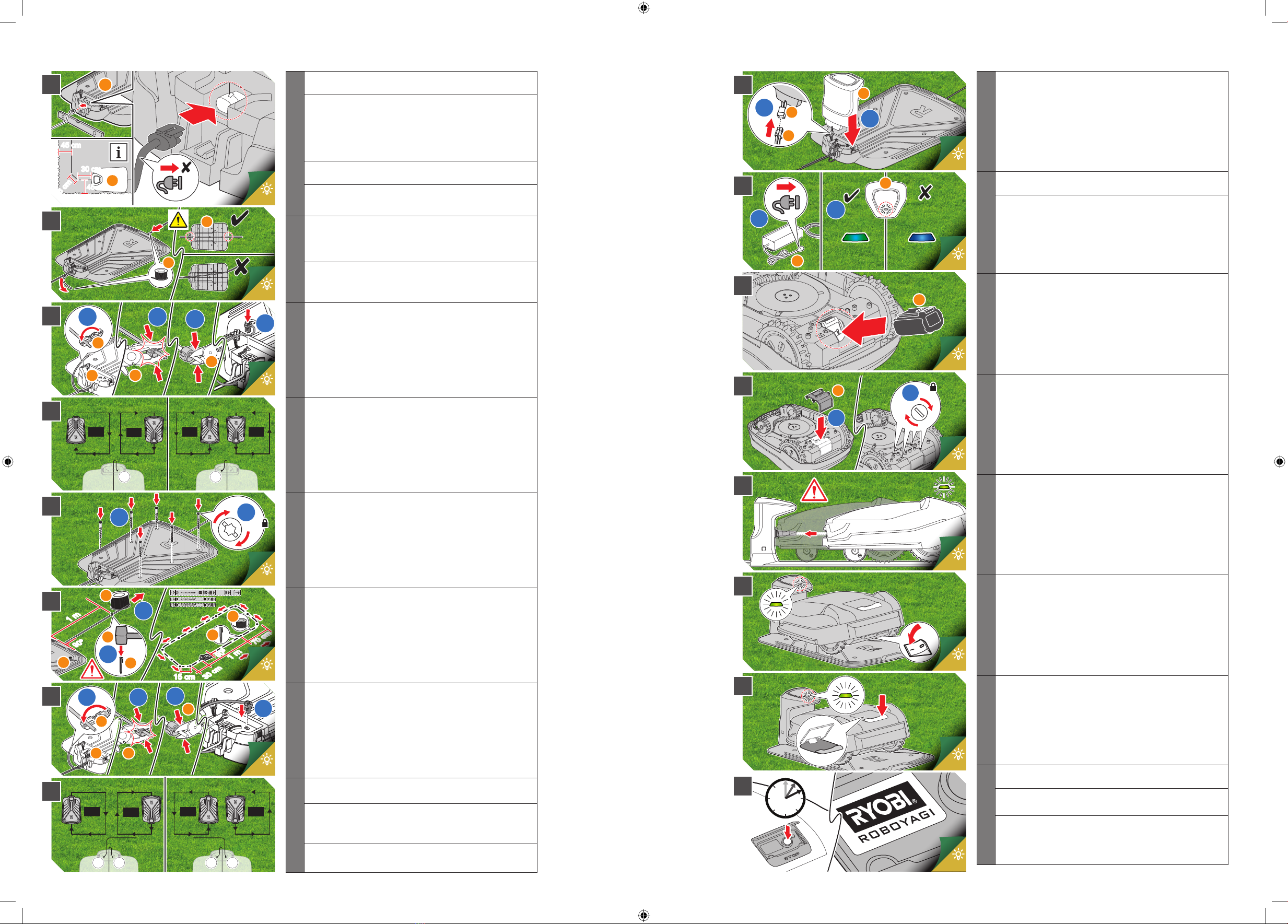
1
Plan the charging pad placement and perimeter wire placement
carefully.
Note: The charging pad may be positioned to have a docking
direction of either clockwise (CW) or counterclockwise (CCW).
ROBOYAGI drives in this direction along the perimeter wire
when returning to the charging station. Use the supplied ruler
to allow a space of 30 cm plus 15 cm at 45° cutting the corner
behind the charging station.
Place the charging pad (c) in a at area convenient to the power
source.
Plug in the power supply (d) from the transformer into the
charging pad. Do not plug into the mains electricity yet.
2
Run the perimeter cable under the base of the charging pad.
Note: Make sure that the perimeter cable is straight and within
the channel.
3
At the end of the perimeter cable running under the charging pad
– secure the wire connector (f) with pliers to ensure a very tight
t, breaking the insulating sleeve of the perimeter wires.
4
Note: Depending on your charging pad placement, you need
to connect the perimeter wire in either CW or CCW direction. If
CW, the perimeter wire going under the charging pad connects
into terminal 2 (T2). If CCW, the perimeter wire going under the
charging pad connects into terminal 1 (T1).
5
Secure the charging pad with the screws (i) provided.
6
Continue following the process of laying the perimeter cable
using the guidance rulers provided in the packaging lid, ensuring
that the rst metre of perimeter cable at the front of the charging
pad continues straight at a 90° angle for at least 1m. Apply
pegs (h) as detailed. Avoid laying the perimeter cable on slopes
greater than 36% or 24°. When laying the perimeter wire at a
corner, ensure that the angle of the wire is greater than 90°,
smoothing out the corners where possible.
7
On the perimeter cable leading to the charging pad – secure the
wire connector (f) with pliers to ensure a very tight t, breaking
the insulating sleeve of the perimeter wires.
8
Fix the connector onto the available terminal (T1 or T2).
Note: Failure to plug the perimeter wire connectors into the
correct terminal will result in a failure alert “Outside of the
boundary’’. If this happens, switch the terminals around.
Now you have completed the perimeter setup!
9
Connect the charging station to the charging pad, and ensure
that the clips are secure and the tower is rmly attached.
10
Plug the transformer into the mains electricity. The charging
station initialises and lights up CYAN for 10 seconds.
Conrm that the perimeter wire is a closed loop by observing a
solid green light on the top to the charging station.
11
Install the battery (e), and make sure that you hear a positive
CLICK.
12
Attach the battery cover (o) securely.
13
Place the ROBOYAGI onto the charging pad, ensuring that the
charging port is positively engaged.
14
Turn on the ROBOYAGI on the master on/o switch, located
underneath the unit.
15
Press the stop button to open the cover.
16
Press the round selector knob for 3 seconds to activate the
display.
Follow the on-screen instructions on how to customise the set up
your ROBOYAGI.
Note: Your ROBOGYAGI may need to be charged before it starts
cutting.
g
1
2
m
h
h
c
1 m
1 m
70 cm
30 cm
90º
90º
15 cm
g
1
2
3
4
5
6
7
8
10-13
13
13
13
13-14
14
9
10
11
12
13
14
15
16
14-15
14-15
15
15
15-16
15-16
16-17
16-17


