S-Lighting S-BLINDER User manual

S-BLINDER
USER MANUAL

TABLE OF CONTENTS
1. IntroductIon 3
2. Safety InformatIon 3
3. Product InformatIon 4
3.1 SPecIfIcatIon 4
3.2 cleanIng and maIntenance 5
3.3 dMX-512 7
4. dISPlay menu 9
5. dMX functIonS and valueS 10

3 www.slservice.pl S-LIGHTING S-BLINDER
1. IntroductIon
2. Safety InformatIon
Thank you for choosing our product! Please consult
this manual for any safety reasons, to ensure a painless
and trouble-free operation, as well as for any reference
needed.
We encourage you to check out our other products at our
website: http://slservice.pl/ !
To maintain this device’s condition and to ensure a safe
operation, it is absolutely necessary for the user to follow
these safety instructions and warning notes written in this
user manual.
- This device falls under protection-class I. Therefore it is essential
that the device should be earthed.
- The electric connection and installation should be done
by qualied personnel in order to minimize the risk
of accidental electric shock and damaging the device.
- Always disconnect from the mains, when the device is not
in use or before cleaning it. Only handle the power cord by the plug.
Never pull out the plug by tugging the power cord.
- Make sure the power cord is never crimped or damaged
by sharp edges - if this would be the case, immediately
replace the cable for the exact same type.
- Before connecting the unit to the mains, make sure it is not
damaged mechanically. If you notice any signs of damage,
you should contact your dealer immediately. In this case
do not connect the device to the mains.
- Make sure that the available voltage is not higher than 240V.
- Never look directly into the light source (especially if you have
any epileptic past)!
- The device must be installed on a stable structure. Always use steel
security cable to attach the device to a stable structure.
- Do not use this device in high humidity conditions and at tempera-
tures above 40°C.
- Do not cover the ventilation slots when operating to avoid internal
overheating.

S-LIGHTING S-BLINDER www.slservice.pl 4
Power supply voltage: 100-240V
Power consumption: 400W
Voltage frequency: 50/60Hz
Diode type and power: 100W LED
Number of diodes: 4pcs
Color temperature: 3000K
Brightness: 1300 lm @5m
Beam angle: 60° per beam
Scan rate: 7000 Hz
Dimming: 16-bit dimmer
DMX standard: DMX 512
DMX channels: 1/3/4/9/10
AC IN: powerCON
AC OUT: powerCON
DMX IN: XLR - 3 pin
DMX OUT: XLR - 3 pin
IP Rating: IP65
Cooling: Passive
Height [cm]: 37.3
Width [cm]: 37.3
Depth [cm]: 19.3
Weight [kg]: 9
3. Product InformatIon
3.1 SPecIfIcatIon
- CAUTION: This product’s housing may be hot when lights
are operating.
- DO NOT connect this product to a dimmer or rheostat.
In case of a serious operating problem stop using this product
immediately!
Important:
Damages caused by a disregard of this user manual are not subject
to warranty or any liability.
5 www.slservice.pl S-LIGHTING S-BLINDER
3.2 cleanIng and maIntenance
There are no servicable parts inside the device. Maintenance and
service operations are only to be carried out by authorized dealers.
If you need any spare parts, please use only genuine parts.
If the power supply cable of this device becomes damaged,
it has to be replaced by authorized dealers only, in order
to avoid hazards.
Never remove the ground pins from power cord nor spin
any cooling fan with compressed air, as this can damage the compo-
nents in your xture.
If you have further questions, please contact your dealer.
We recommend a frequent cleaning of the device, as dust,
smoke and other debris will build up on the optics and ho-
using. After disconnecting the power wipe the devi-
ce with a soft, lint-free and damp cloth. Never use alcohol
or solvents, as these may damage the nish. A dry paint brush is an
excellent tool to remove surface dust.
Be sure to periodically check for loose parts that could damage the
device or potentially allow the device to cause injury. Make sure all
overhead and wall installations have a secondary safety accessory
installed, such as safety cable rated for your device type and size.
Check the power cord as well, make sure there is no damage that
could cause electrical shock, never remove the ground pin. There are
no user-servicable parts in this device. Do not attempt to open and
repair the xture.
CAUTION! Always disconnect from mains before
starting any maintenance operation!
Before replacing a fuse, disconnect the power
cord! Always replace with the same type
and rating of fuse!
S-LIGHTING S-BLINDER www.slservice.pl 6
Mounting & rigging
This device can be mounted in any orientation (vertical, horizontal).
Always make sure there is adequate ventilation and no ammable
surfaces within 2 feet (0.6 meters) of the device. You can mount
the device using clamps or with threaded bolt type hardware.
Always install the included safety eyebolt and cable when mounting
in overhead or wall locations.
Expected LED lifespan
LEDs gradually decline in brightness over time, mostly because
of heat. Packaged in clusters, LEDs exhibit higher operating
temperatures than in ideal, single LED conditions. For this
reason, using clustered LEDs at their fullest intensity signicantly
reduces the LEDs’ lifespan. Under normal conditions, this lifespan
can be 40’000 to 50’000 hours.
If extending this lifespan is vital, lower the operating temperatu-
re by improving the ventilation around the product and reducing
the ambient temperature to an optimal operating range. In addition,
limiting the overall projection intensity may also help to extend
the LEDs’ lifespan.
Warning: Do not mount the xture in the
ventilation path of a nearby heating supply
duct. The heated airow will cause device
failure due to overheating.
7 www.slservice.pl S-LIGHTING S-BLINDER
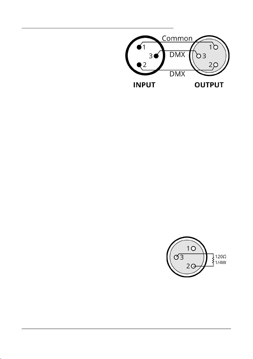
3.3 dMX-512
- 2-conductor twisted pair plus a shield,
- maximum capacitance between conductors - 30pF/ft,
- maximum capacitance between conductor & shield - 55 pF/ft,
- maximum resistance of 20 ohms / 1000 ft (304.8m in normal),
- nominal impedance 100 - 140 ohms.
Cable connectors:
Cables must have a male XLR connector on one end and a female
XLR connector on the other end (duh!).
A word on termination: DMX is a resilient communication protocol,
however errors still occasionally occur. Termination reduces signal
errors, and therefore best practises include the use of terminator
in all circumstances. If you are experiencing problems with erratic
device behavior, especially over long cable runs, a terminator may
help improve performance.
CAUTION: Do not allow contact between the common and the
device’s chassis ground. Grounding the common may cause
a ground loop, and your device may perform erratically. Test cables
with an ohm meter to verify correct polarity and to make sure
the pins are not grounded or shorted to the shield or each other.
To build your own DMX Terminator:
Obtain a 120-ohm, 1/4-watt resistor and
wire it between pins 2 & 3 of the last
xture. They are also readily available from
specialty retailers. A DMX terminator
To link devices together you’ll
need data cables. You should use
data grade cables that can carry
a high quality signal and are
less prone to electromagnetic
interference. For instance,
Belden© 9841 meets the
specications for EIA RS-485 applications. Standard microphone
cables will probably be OK, but note that they cannot transmit
DMX data as reliably over long distances. In any event, the cable
should have the following characteristics:

S-LIGHTING S-BLINDER www.slservice.pl 8
First device
in chain
Signal IN
To the
next
device
Next device
in chain
Step 1: Connect the male
connector of the DMX cable
to the female connector (output)
on the controller.
Step 2: Connect the female
connector of the DMX cable
to the rst device’s male
connector (input).
Note: It doesn’t matter which device address
is the rst one connected. We recommend
connectingthe devicein termsof theirproximi-
ty to the controller, rather than connecting
the lowest device number rst, and so on.
Setting up DMX control
Step 3: Connect other devices in the chain from output to input
as above. Place a DMX terminator on the output of the nal device
to ensure the best communication.
Fixture linking (Master/Slave Mode)
1. Connect the (male) 3-pin connector side of the DMX cable to the
output (female) 3-pin connector of the rst device.
2. Connect the end of the cable coming from the rst device, which
will have a (female) 3-pin connector to the input connector of the
next device consisting of a (male) 3-pin connector. Then, proceed
to connect from the output as stated above, to the input
of the following device (and so on).
3-Pin / 5-Pin
If you use a controller with a 5 pin DMX output connector, you will
need to use a 5 pin to 3 pin adapter. They are widely available over
the Internet and from specialty retailers, but if you’d like to build
your own, the table below details a proper cable conversion:
Conductor 3-Pin female (Output) 5-Pin male (Input)
Ground/Shield Pin 1 Pin 1
DMX Data (-) Pin 2 Pin 2
DMX Data (+) Pin 3 Pin 3
Not used. no connector Pin 4
Not used. no connector Pin 5

9 www.slservice.pl S-LIGHTING S-BLINDER
Address
Cong
System Info
Color Menu
DMX Mode
Temp
LED1
LED3
Set DMX Address
Channel 2CH
Channel 9CH
Disable
Fast Mode Able
Channel 4CH
Channel 10CH
Manual Mode
Hour
LED2
LED4
Channel 1CH
4. dISPlay menu
S-LIGHTING S-BLINDER www.slservice.pl 10
1 0-255 Master Dimmer
1 0-255 Master Dimmer
2 0-255 Master Dimmer Fine
3 Strobe
0-015 No Function
16-255 Strobe (slow <--> fast)
1 0-255 Master Dimmer
2 0-255 Master Dimmer Fine
3 Strobe
0-015 No Function
16-255 Strobe (slow <--> fast)
4 0-255 Dimmer LED Head 1
5 0-255 Dimmer LED Head 2
6 0-255 Dimmer LED Head 3
7 0-255 Dimmer LED Head 4
8 0-035 No Function
36-071 Round Up
72-107 Round Down
108-143 Round Up and Down
144-179 SIN Up
180-215 4-colors
216-255 Random Eect
9 Dimmer Mode
0-063 Linear
64-127 Square
128-191 Invert Square
192-255 S-Curve
1 0-255 Dimmer LED Head 1
2 0-255 Dimmer LED Head 2
3 0-255 Dimmer LED Head 3
4 0-255 Dimmer LED Head 4
CH1 Mode
3CH Mode
9CH Mode
4CH Mode
5. dMX functIonS and valueS
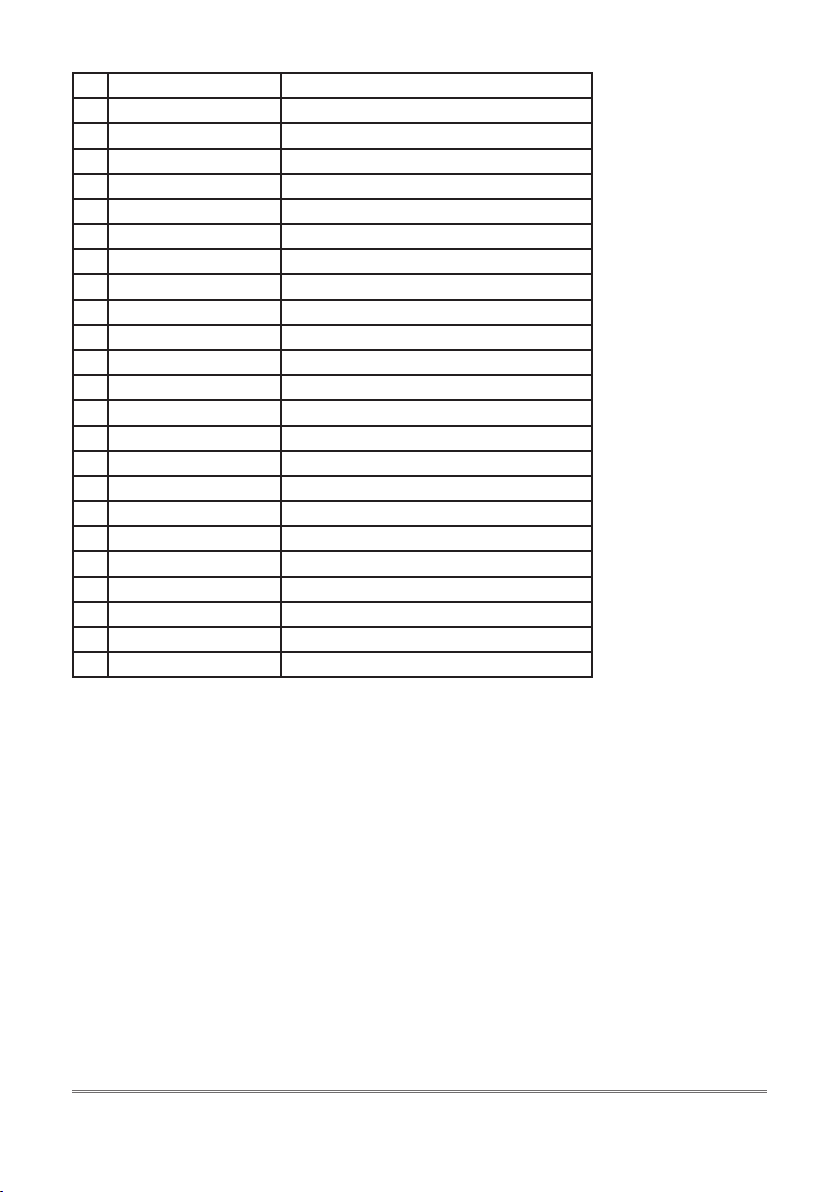
11 www.slservice.pl S-LIGHTING S-BLINDER
1 0-255 Master Dimmer
2 0-255 Master Dimmer Fine
3 Strobe
0-015 No Function
16-255 Strobe (slow <--> fast)
4 0-255 Dimmer LED Head 1
5 0-255 Dimmer LED Head 2
6 0-255 Dimmer LED Head 3
7 0-255 Dimmer LED Head 4
8 0-035 No Function
36-071 Round Up
72-107 Round Down
108-143 Round Up and Down
144-179 SIN Up
180-215 4-colors
216-255 Random Eect
9 Dimmer Mode
0-063 Linear
64-127 Square
128-191 Invert Square
192-255 S-Curve
10 Dimmer Speed
0-254 No Tungsten Eect
255 Tungsten Eect (fast <--> slow)
10CH Mode
Table of contents


