Energetic Lighting ZDL1132 User manual

2
1
Please read and understand this entire manual before attempting to assemble, operate or
install the product. Failure to do so could lead to electric shock, fire or other injuries that
could be hazardous or even fatal.
• Be sure the electricity to the wires you are working on is shut off. Either remove the fuse
or turn off the circuit breaker.
• This product must be installed in accordance with local, state and national electrical
codes.
• Changes or modifications not expressly approved by the party responsible for compliance
could void the user’s authority to operate the equipment.
• This fixture is NOT suitable for use on a dimming circuit.
NOTICE
• This device complies with Part 15 of the FCC Rules. Operation is subject to the following
two conditions: (1) This device may not cause harmful interference, and (2) this device
must accept any interference received, including interference that may cause undesired
operation.
• This equipment has been tested and found to comply with the limits for a Class B digital
device, pursuant to part 15 of the FCC Rules. These limits are designed to provide
reasonable protection against harmful interference in a residential installation. This
equipment generates, uses and can radiate radio frequency energy and, if not installed and
used in accordance with the instructions, may cause harmful interference to radio or
television reception, which can be determined by turning the equipment off and on. The
user is encouraged to try to correct the interference by one or more of the following
measures:
- Reorient or relocate the receiving antenna.
- Increase the separation between the equipment and the receiver.
- Connect the equipment into an outlet on a circuit different from that to which the receiver
is connected.
- Consult the dealer or an experienced radio/TV technician for help.
LED Landscape Lighting
Installation Instructions
Questions, problems, missing parts? Before returning to your retailer, call our customer
service department at 1-866-381-2688 from 9 a.m. - 5 p.m., CT, Monday - Friday, English and
Mandarin.
www.yankon-lighting.com
Part Item Name Qty.
APower supply / controller 1
PACKAGE CONTENTS
SAFETY INFORMATION
BPathlight fixture 4
CDirectional spotlight fixture 2
DDirect burial cable 60-ft
LIGHTING
C
B
A
D
ITM./ ART. 1573171
IMPORTANT, RETAIN FOR FUTURE REFERENCE: READ CAREFULLY
MODEL # ZDL1132

WARNING
• Risk of Electric Shock - when used outdoors, install only to a covered Class A GFCI
protected receptacle that is weatherproof with the power unit connected to the receptacle. If
one is not provided, contact a qualified electrician for proper installation. Ensure that the
power unit and cord do not interfere with completely closing the receptacle cover.
• The low voltage direct burial cable shall
(a) be protected by routing in close proximity to the luminaire or fitting, or next to a building
structure such as a house or deck;
(b) not be buried except for a maximum 6 inches (15.2 cm) in order to connect to the main
low voltage cable; and
(c) have the length cut off so that it is connected to a connector within 6 inches (15.2 cm)
from a building structure, a luminaire, or fitting.
• Expansion sets are available for additional luminaires to be installed on the same power
supply circuit, note that each power supply can only allow a maximum of ten (10)
luminaires to be linked on the same circuit cable; total luminaire wattage not to exceed
48W per power supply circuit.
3
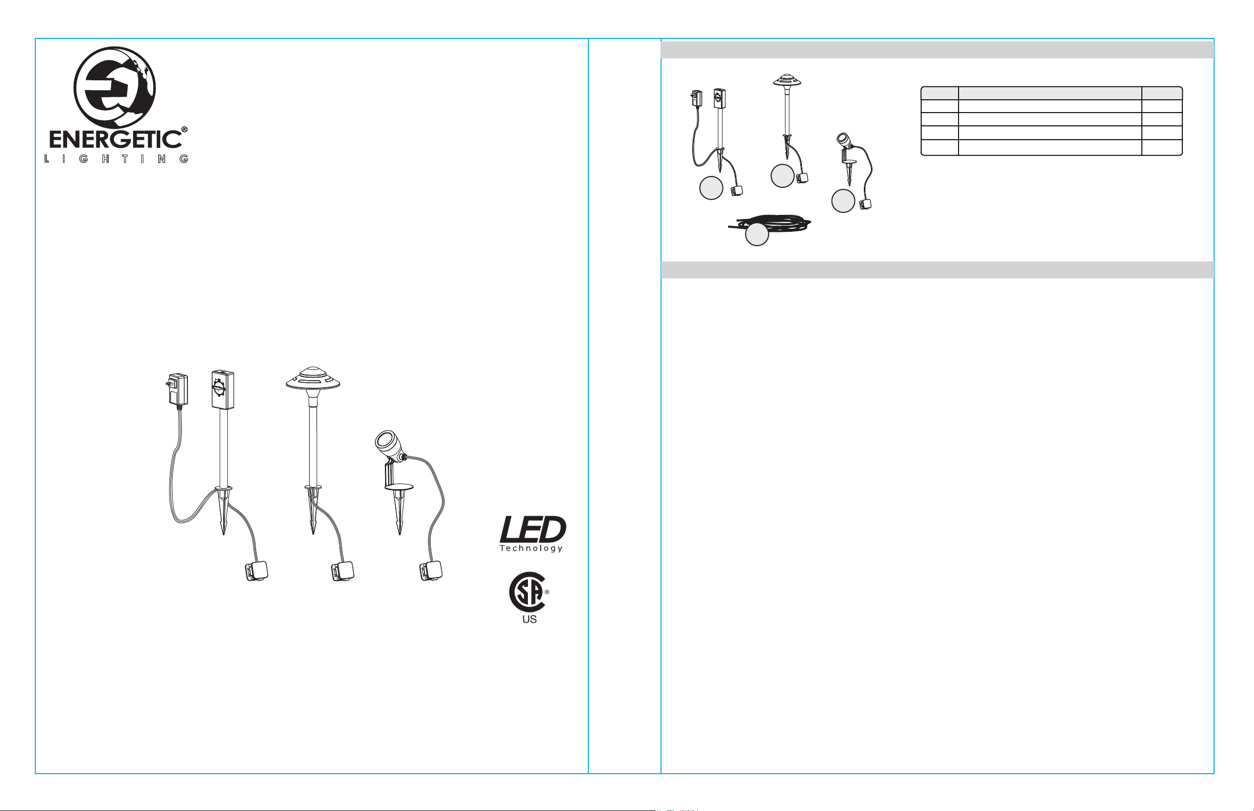
Before beginning assembly of product, make sure all parts are present. Compare parts with
package contents list and hardware contents list. If any part is missing or damaged, do not
attempt to assemble the product.
Estimated Assembly Time: 20 minutes
SAFETY INFORMATION
PREPARATION
4
INSTALLATION INSTRUCTIONS
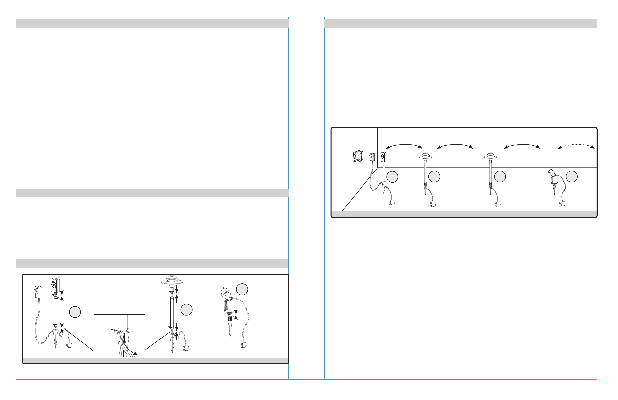
1. Assemble the power supply/controller (A), pathlight fixtures (B) and directional spotlight
fixtures (C) by turning each component into it’s corresponding adjacent part’s threaded fitting.
The power supply/controller (A) consists of 3 parts: controller body, extension tube, and
mounting stake.
The pathlight fixtures (B) each consist of 3 parts: light head, extension tube, and mounting
stake.
The directional spotlight fixtures (C) each consist of 2 parts: light head and mounting stake.
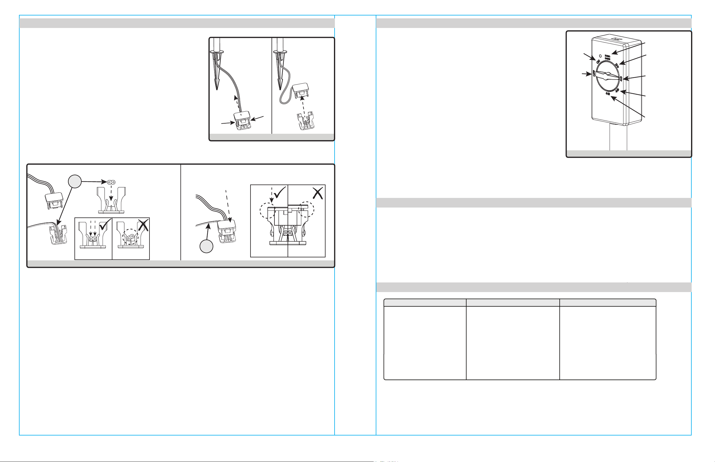
NOTE: The power supply/controller (A) and pathlight fixture (B) requires that the cord at the
base of the extension tube be passed through the slot opening before the stake can be
attached to the extension tube threading.
Fig. 2
2. Determine the desired location for each piece of the kit. Note that the power supply / controller
(A) assembly will need to be located near a power outlet within the distance provided by the
power cord to the outlet plug adapter.
NOTE: Do NOT push the fixture top when inserting the stakes into the ground, press down only
on the round base of the stake as shown in fig. 2 above. If the ground is too hard-packed,
use a screw driver or similar tool (not provided) to loosen the soil and pre-punch the stake
path.
60-ft of direct burial cable is provided with each kit package, however, expansion sets are
available (sold separately) providing additional fixtures and direct burial cable.
NOTE: A maximum of 10 fixtures can be installed on a single power supply circuit.
AB B C
Fig. 1
INSTALLATION INSTRUCTIONS
Slot
Opening
Cord
Path
AB
C

5
INSTALLATION INSTRUCTIONS (CONT’D)
Press
Press back
together
IncorrectCorrect
Press
Lift up
3. Each fixture will need to be connected to the power
supply/controller through the wire connector at the
end of each lead cord. Release the connector cover
by squeezing the latches on opposite sides of the
connector as shown in the figure, while lifting the
cover to separate into two halves.
Fig. 3
4. Lay the direct burial cable (D) so that the orientation is as shown in the figure, ensure that the
cable sits flush at the base of the connector. Snap back together the previously removed upper
half of the connector to complete the connection of the fixture to the direct burial cable (D) line.
Pay attention to the upper seams between the two halves of the connector, firmly press
together until the seam is closed without any gaps. Repeat this for each fixture connector to
complete the circuit.
NOTE: Cut any excess cable slack so that the cable ends are within 6-inches of a connector.
Route the cable in close proximity to the fixtures, connectors, or next to a building structure,
such as a house or deck.
Bury the direct burial cable (D) not more than 6-inches from the surface.
Fig. 4
D
6
INSTALLATION INSTRUCTIONS (CONT’D)
OFF
ON
Dusk-to-Dawn
Timer 2 hours
after dusk
Timer 4 hours
after dusk
Timer 6 hours
after dusk
Timer 8 hours
after dusk
5.
Once all fixtures have been connected to the power
supply / controller, test the connection by plugging in
the power adapter to building power source and turning
the controller dial to “ON”. Ensure that all connected
lights turn on appropriately.
Bury all exposed lead wire at a depth of maximum
6-inches.
Turn the controller dial to the desired setting:
ON: Always on
Dusk-to-Dawn: photocell self-regulated on/off
2Hr Timer: Lights stay on for 2-hours after dusk
4Hr Timer: Lights stay on for 4-hours after dusk
6Hr Timer: Lights stay on for 6-hours after dusk
8Hr Timer: Lights stay on for 8-hours after dusk Fig. 5
Clean with a mild, non-abrasive glass cleaner and soft cloth. Do NOT use solvents or cleaners
containing abrasive agents. When cleaning the fixture, make sure the power is turned off, and
any liquid spray should be applied to the cleaning cloth and not sprayed directly onto the fixture
itself.
CARE AND MAINTENANCE
TROUBLESHOOTING
Problem Possible Solution Corrective Action
Fixture does not light.
1. Power is off.
2. Incomplete wire
connection.
3. Light flicker
1. Check circuit breaker
or wall switch.
2. Check wire splices at each
connector.
3. Check if photocell sensor
is periodically blocked by
shade from a moving object.
D
IncorrectCorrect

7
WARRANTY
This fixture has a 5-year warranty. If it fails or you are not satisfied with its performance,
please contact Yankon Lighting Inc. for instructions on replacement. This replacement is the
sole remedy available. Customer Service: Yankon Lighting, Inc. 1581 Corporate Dr.
Contact customer service : 1-866-381-2688
(9 a.m. - 5 p.m., CT, Monday - Friday, English and Mandarin)
Made in China
Distributed by:
Costco Wholesale Corporation
P.O. Box 34535
Seattle, WA 98124-1535
USA
1-800-774-2678
www.costco.com
Costco Wholesale Canada Ltd.*
415 W. Hunt Club Road
Ottawa, Ontario
K2E 1C5, Canada
1-800-463-3783
www.costco.ca
*faisant affaire au Québec sous
le nom les Entrepôts Costco
Importado por:
Importadora Primex S.A. de C.V.
Blvd. Magnocentro No. 4
San Fernando La Herradura
Huixquilucan, Estado de México
C.P. 52765
RFC: IPR-930907-S70
(55)-5246-5500
www.costco.com.mx
Costco Wholesale Australia Pty Ltd
17-21 Parramatta Road
Lidcombe NSW 2141
Australia
www.costco.com.au
Costco Wholesale UK Ltd /
Costco Online UK Ltd
Hartspring Lane
Watford, Herts
WD25 8JS
United Kingdom
01923 213113
www.costco.co.uk
Costco Wholesale Spain S.L.U.
Polígono Empresarial Los Gavilanes
C/ Agustín de Betancourt, 17
28906 Getafe (Madrid) España
NIF: B86509460
900 111 155
www.costco.es
Costco Wholesale Iceland ehf.
Kauptún 3-7, 210 Gardabaer
Iceland
www.costco.is
Costco France
1 avenue de Bréhat
91140 Villebon-sur-Yvette
France
01 80 45 01 10
www.costco.fr
Costco Wholesale Japan Ltd.
3-1-4 Ikegami-Shincho
Kawasaki-ku, Kawasaki-shi,
Kanagawa 210-0832 Japan
0570-200-800
www.costco.co.jp
Costco Wholesale Korea, Ltd.
40, Iljik-ro
Gwangmyeong-si
Gyeonggi-do, 14347, Korea
1899-9900
www.costco.co.kr
Costco Wholesale New Zealand Limited
2 Gunton Drive
Westgate
Auckland 0814
New Zealand
Costco (China) Investment Co., Ltd.
Room 1003, Block 2, 2388 Xiupu Road,
Pudong New Area, Shanghai
China 201315
+86-21-6257-7065
Costco Wholesale Sweden AB
Saluvägen 5
187 66 Täby
Sweden
This manual suits for next models
1
Other Energetic Lighting Lighting Equipment manuals

Energetic Lighting
Energetic Lighting E1WPA Series User manual

Energetic Lighting
Energetic Lighting E1PL Series User manual

Energetic Lighting
Energetic Lighting E1WPM Series User manual

Energetic Lighting
Energetic Lighting ELYRTD Series User manual

Energetic Lighting
Energetic Lighting E4FMR Series User manual

Energetic Lighting
Energetic Lighting E1ALB Series User manual

Energetic Lighting
Energetic Lighting E2WPA Series User manual

Energetic Lighting
Energetic Lighting E2FMA Series User manual

Energetic Lighting
Energetic Lighting E2WPC Series User manual

Energetic Lighting
Energetic Lighting E1ALB30 User manual