SABINE SWASS-EXT User manual

Included with the SWASS-EXT
• Onepairofantennas(left&right),eachwith
micstandmountsattached
• TwoEuropeanmicstandadaptorinserts
• FourstraightTNCmalecrimpconnectors
• Two right angle TNC male to female con-
nectors
• Operating Guide
2.4 GHz Smart Spectrum®
Extension Antenna Kit
SWASS-EXT
SWASS-EXT-2
Operating Guide
foruse withmodels:
SWA6SS, SW71-R, SW72-R, & SW72-NDR
SWASS-EXT benefits
• Wallmountormic-standmount
• StraightandrightangleTNCconnectors
• 130degreereceptionpattern
• +18 dB gain (SWASS-EXT)
• +22/+44dBswitchablegain(SWASS-EXT-2)
• Wood-tonefinish
• Phantom-poweredfrom either thereceiveror
the distribution amp; Power LED indicator
(SWA-EXT-2)

2
OVERVIEW
The SWASS-EXT Antenna Extension Kit is designed for use with Sabine SWM7000 2.4
GHz wireless microphone receivers and antenna distribution amplifiers. The SWASS-
EXTallowsfor optimalplacementof externalantennasfor maximumwirelessperformance.
One SWASS-EXT kit can accommodate up to 70 receiver channels. (See block diagram
detail on page 10).
A
NTENNA
P
LACEMENT
Extension antennas should be placed in an open area within visual range of the intended
transmitterlocations.Note that therangeofaTrue Mobilitytransmitterisabout 100 meters,
but that structural objects can reduce that range.
C
AUTIONS
• Sincetheinstallation of the antennas influences theoperatingefficiencyof the receiver,
the most important rule is to minimize the distance between receiving antenna and
transmitter for better reception and performance. Make sure the antennas can “see”
the transmitter.
• Keep the system away from electrical-noise sources (electric motors, refrigerators, arc
welders, etc.). Place the SWM7000 receiver or SWA6SS Antenna Distribution Ampli-
fier at least 1.5 meters above floor level. Keep all transmitters at least 3 meters away
from a receiver antenna.
A
NTENNA
C
ABLING
& C
ABLE
L
OSS
While an extension antenna affords the opportunity to increase the distance from trans-
mitter to receiver, there is a loss of signal in the interconnecting cable that limits that
distance. The maximum connection length is determined by the type of cable used, and
the degree of signal attenuation acceptable.
Let’s presume that an acceptable degree of loss over the total cable run is 6 dB. Without
external signal boosts, the different cables shown in the table would then allow maximum
lengths ranging from less than 4 M (RG-58) to 24 M (RG8/U). Thus, for a passive exten-
sion antenna, your choices are to limit the cable run, or increase your budget and buy the
more expensive, thicker cable.
RG58 9203 Polyethylene #20 Stranded -16.29 14 TNC
RG58/AU 9311 Foam #20 Stranded -11.10 20 TNC
Polyethylene
RG212/U 9861 Polyethylene #15.5 solid, -6.11 36 N
silver plated
RG8/U 9913 Semi-solid #10 solid -2.50 88 N
Polyethylene
RG142 83242 Teflon #18 solid, -6.54 34 TNC
silver plated
Coaxial Cable Attenuation Table
Cable
Type Belden
# Insulation Center
Conductor
10 Meter
Attenuation
(in dB)
MaximumPractical
Distance
(usingSWASS-EXT-2
at +22dB, in meters) Connector
Type

3
LIT-SWASS-EXT-OP-051123.pmd
© 2005 Sabine, Inc
Fortunately, Sabine’s SWASS-EXT Active Extension Antenna offers a far better, more
cost-effective solution, due to its built-in active 18 dB signal boost. In the case of low-cost
RG-58 cable, adding an SWASS-EXT to your setup increases the acceptable maximum
cable run by more than 4 times, to 14 meters. With RG-8 cable, the maximum length is
extended to 88 meters!
Powerforthe ExtensionAntennaisdelivered fromanySabineSWM7000 seriesreceiveror
SWA6SSAntennaDistributionAmplifier.
Anadditionaladvantage of usingSabine’sSWASS-EXTExtensionAntennastemsfrom its
morefocused,directionalnature. Sabinereceiver’scoaxialdipoleantennas(standardequip-
mentthatmountdirectlyonthefrontorrearpanelsofthereceiverorSWA6SS)aremoreomni
directionalinnature. Incontrast,theSabine’sExtensionAntennaissensitivetoRFreception
ina180-degree arcinfrontofitsmountedposition. It extendssensitivitytothe frontandoff-
axissidelocationsasit increasesrearRF rejection.
Themultiplefunctions(relocationofantenna,boostofsignal,directionalsensitivity)ofSabine’s
ExtensionAntennameantherearemanyapplicationsinwhichitsadditiontoyoursystemcan
greatlyenhanceperformance. Here’sapartial listofsuch applications:
1. Antennarepositioning. Providessolutionswhenreceiverplacementoptionsarelimitedor
challenging. Sabine’sExtensionAntenna’smultiplemountingoptions allowhigherplace-
ment(wallmountormicrophonestandmount).
2. Barriersinterrupting transmission. Anytimeabarrierinterfereswith transmissionand
reception,Sabine’sSWA-SSEXTcanbemountedonthetransmittersideofthebarrierwith
cableconnectionsmade onthereceiverside. The mostcommonsituationof thisnature
wouldarisewhenreceiverandtransmitterarelocatedinseparaterooms.
3. Expandedordirectionalsensitivity required. Sabine’sExtensionAntennapicksupina
180-degreearc,focusedtowardsthe front. Receptioninthis arcisenhanced.
4. Rear RF rejection required. Because Sabine’s ExtensionAntenna is less sensitive to
signals received from the rear, it can be positioned to reject any such directional RF
interference.
5. Extendedoperationalrange. Givenapotentialmaximumcablelengthofalmost90meters
fromExtensionAntennatoreceiver,Sabine’sSWASS-EXTallowsmoreoptionsforextend-
ingthedistancebetweentransmitterandreceiver.ConsiderthatRFsignalstrengththrough
airis diminishedbythesquareofthedistance(twice asfaraway=¼ thesignalstrength),
whilesignallossthrough cableis(roughly)inverselyproportional (twice asfaraway= ½
thesignal). Thatmeansyoucanuseanextensionantennatoreplacetransmission-through-
airwithtransmission-through-cable,tohelpminimizesignalloss.
6. SwitchingGain (SWASS-EXT-2). Thismodel allowsfortwodifferentgainsettings. “LO”
is+22dB,and“HI”is+44dB. Thereshouldbeaminimumof12dBofcablelossbeforethe
antennaisswitchedinto high gain mode. If highgainisactivatedwith less than 12dBof
cableloss thereceiverfrontendmaygetoverloaded. Theswitchshouldbethoughtofas
high = long cable, low = short cable. Refer to the chart at left and use high gain only for
extendingthemaximumpracticaldistanceofthecableyouareusing.

4
SWASS-EXT 2.4 GH
Z
E
XTERNAL
A
NTENNA
Exterior case
(wood-grained) Antenna
component Spacer Mic stand
mounting
bracket
Wall
mount
metal
bracket
TNC
connector
Mic stand
connector
White
plastic
nut
2
1
Line-of-sight path
GENERAL INSTRUCTIONS
Locate and install the Left and Right antennas so that they are within line-of-sight of
intended wireless microphone locations.
Connect the SWASS-EXT “Left” and “Right” Antennas to either antenna input on
yourSWM7000 receiverorSWA6SSAntennaDistributionAmplifier. NOTE:SWASS-
EXT antennas are sold in Left / Right pairs and must be installed as such. Do not
install a “Right” antenna with another “Right” antenna; or conversely, a “Left” an-
tenna with other another “Left” antenna.

5
LIT-SWASS-EXT-OP-051123.pmd
© 2005 Sabine, Inc
1
4
3
2
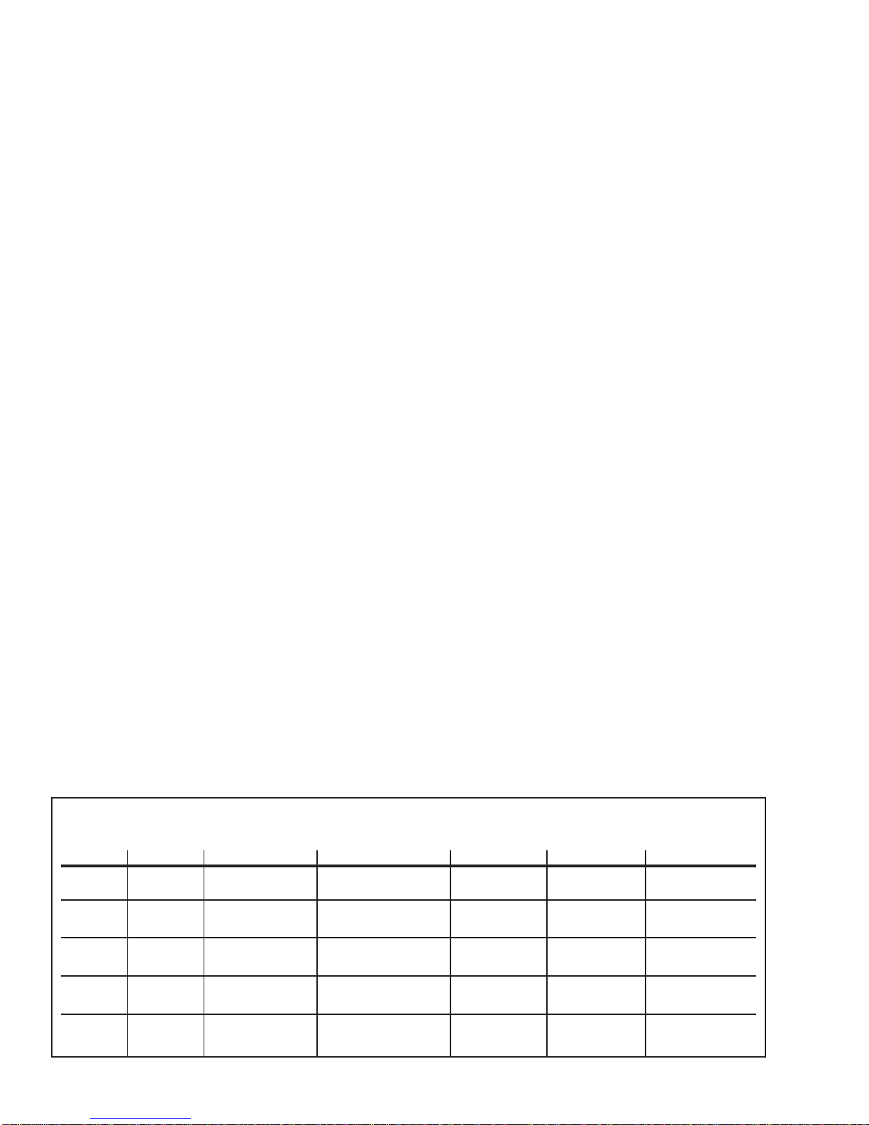
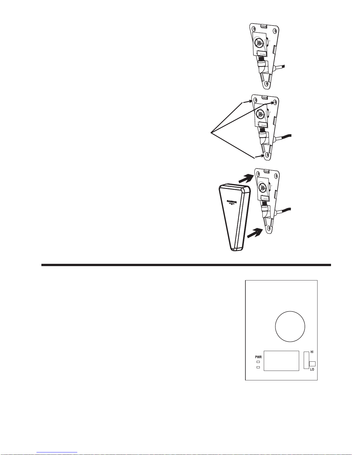
MOUNTING INSTRUCTIONS
SWASS-EXT Antennas can be permanently mounted on wall surfaces, or affixed to the
top of microphone stands for convenient re-positioning.
M
ICROPHONE
S
TAND
M
OUNTING
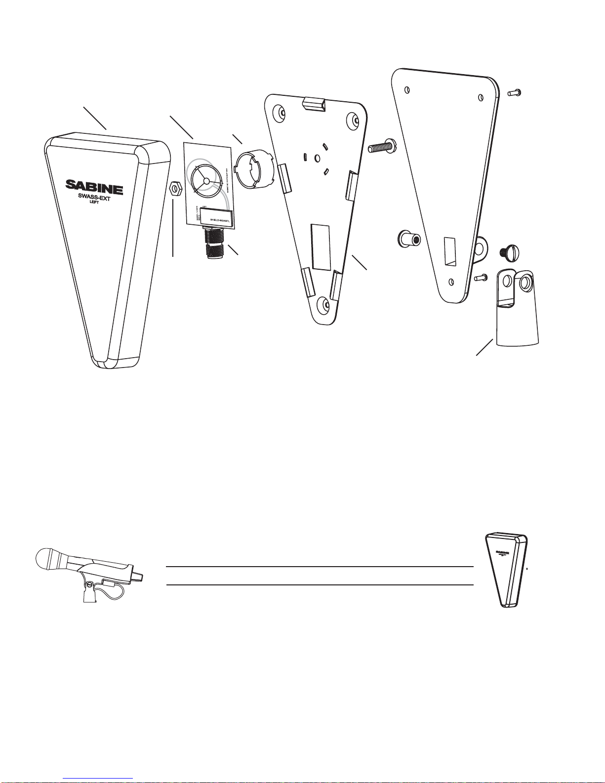
Attach SWASS-EXT Antenna Kits to
microphone stands and position
stands in desired locations.
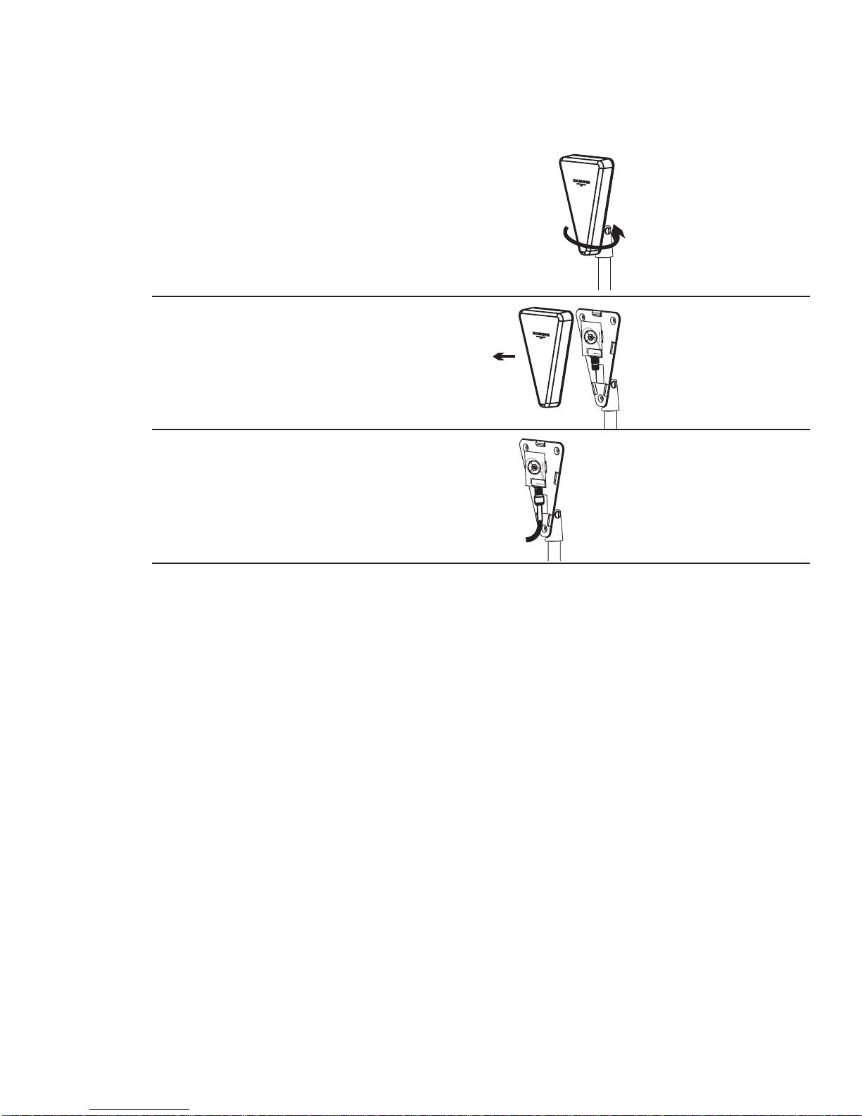
Gently pry the wood-grained exterior
case from the rest of the antenna as-
sembly.
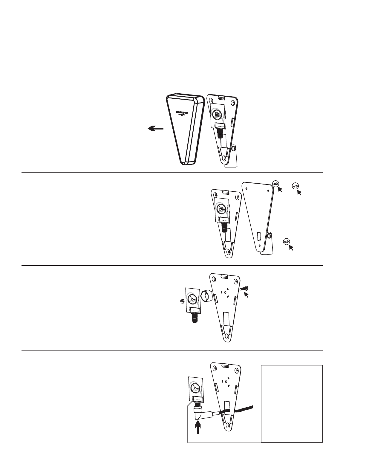
AttachantennacabletoTNCconnec-
tor on the antenna assembly. Hand
tightenonly. Reattachthe wood-grain
exterior case
Placing Extension Antennas
Position the one marked LEFT at
stage left (on the left hand side of a
performer facing the audience) and
so on. When you mount the
extension antennas on a stand or on
a wall, make sure the short end of
the triangle is up.
In order for the system to be effective,
both extension antennas should
be in a good pickup position at all
times but separated by about ten or
fifteen feet if the antennas are within
100 or so feet. Separate them about
20 to 25 feet in very large rooms or
fields.
If you put the antennas too far apart, i.e.,
at opposite ends of the room, or in
separate rooms, to improve
coverage, diversity is defeated and
you will get dropouts. In other words,
diversity is more important that
coverage. If you mount the
extension antennas in the ceiling,
the antennas metallic backplane must be
orientated parallel to the floor and the
antennas must not be blocked by pillars,
lights or similar obstructions. Aim the hole
in the plastic cover toward the podium.
Do not daisy-chain extension antennas
together in series. Receivers and the
antenna distribution amp are only designed
to use one left and one right antenna.
Extension Antenna Cables: Use coax cable to
connect the extension antennas to the
receiver or to the ADA. See the chart on
the previous page for cable specifications.
Use the SWATNC-N step-down cable to
connect thicker RG8 cables to the
extension antenna.
The SWASS-EXT extension antennas add
between 10 and 18dB signal strength to
overcome cable loss. Bad crimp
connections are a common cause of
dropouts. Check them carefully!

6
1
2
3
4
W
ALL
M
OUNTING
CAUTION: Be careful not to scratch or damage the interior components of the SWASS-
EXT Antenna Kit. Interior components can be disassembled and reassembled using fin-
gers. Do not use metal pliers, wrenches, screwdrivers or knives to unscrew or tighten
interior antenna components to the metal antenna bracket frame.
Gentlyprythewood-grained ex-
terior case from the rest of the
antenna assembly.
Unscrewtheblackmicrophonemount
from the antenna assembly.
Using fingers only, unscrew the white
plastic nut and remove the antenna
component from the metal bracket.
AttachtheTNCelbowtoyourantenna
cable and thread the elbow through
the rectangular metal cutaway in the
wall-mount bracket. Screw the TNC
elbow onto the separated antenna
component so that the cable end will
go through the cutaway. Tighten fin-
ger tight only.
NOTE: Make sure
the rectangular
silver shield case
(SHIELD-W2ANTL) will
face away from the
bracket when the
component has
been remounted.

7
LIT-SWASS-EXT-OP-051123.pmd
© 2005 Sabine, Inc
6
5
7
NOTE:
wall-mounting
screws not supplied
Reconnectthe antennacomponentto
themetalbracketwiththeTNC elbow
positioned through the cutaway.
Tighten the white plastic nut finger
tight only.
Mount the metal wall-mount bracket
to the predetermined location on the
wall.
Replace the wood-grain antenna ex-
terior case.
SWASS-EXT-2 INSTRUCTIONS
TheSWASS-EXT-2hastwofeaturesnotfoundonthestan-
dardSWASS-EXT: switchablegainandaphantompower
LEDindicator.
1. To switch gain settings, start by removing the cover.
The HI/LO switch is easy to see at the lower right of the
antenna assembly. CAUTION: HI gain is only for ex-
tremelylongcable runs. Refer topage3of thisguidefor
instructionson usingtheHIgainsetting.
2. The Power LED indicates the presence of phantom
power from either the SWA6SS distribution amp or an
SW70 series receiver. Use this LED to verify a good
connectionfromeither ofthese. Ifthe LEDdoesnotlight
afteryoupowerup the receiver or distributionamp,then
youhavea badconnectioninyour RFcabling.

8
INSTALLATION CAUTIONS
Extension Antenna cables — For best results, use high quality coaxial cable with a 50
Ohm impedance. Specifications will vary by cable manufacturer. For best results, use
cable with minimal attenuation. The longer your cable, the more you will reduce the 100-
meter range between transmitter and receiver antenna. A well-placed pair of extension
antennas will eliminate trouble spots and generally improve overall performance of the
wireless.
C
OMMON
S
OURCES
OF
RF I
NTERFERENCE
The typical sources of interference for conventional wireless mics can be high-powered
broadcasters such as radio stations and TV transmitters, or other short-range wireless
devices, including multiple radio microphones operating at the same location (either by
design, or by coincidence), that operate in proximate (or harmonically related) bands.
Lesscommonly, interference may arisefromspuriousoutputsemittedbyelectronic equip-
ment (notably computers, printers, or similar devices with digital clocks), faulty electrical
equipment, neon signs, dimmers and lighting controllers, and so forth.
Many UHF and VHF mics are especially vulnerable because they share the RF spectrum
with the very high-powered transmitters for television. The coming conversion to digital
and high-definition broadcast will increase the problems for UHF and VHF.
The 2.4 to 2.4835 GHz frequency band is not only well above the fundamental (nominal)
transmissionfrequencies ofsuchstronganaloganddigitalbroadcasts, butalsohighenough
to escape interference problems occurring at the strong first harmonic of even the highest
digital television broadcast. The band is approved worldwide for a variety of uses, includ-
ing such diverse transmitters as baby monitors, garage door openers, wireless LANs,
amateur satellite, cordless telephones, etc. Compared to RF broadcast sources like tele-
vision and radio stations, these low power devices produce very localized, short range
interference; furthermore, many of the devices working in the 2.4 GHz range use spread
spectrum transmission and reception. Both of these facts mean such uses of the RF
spectrum are less likely to cause interference with, or suffer from interference from the
use of, Sabine’s systems.
Your first step in checking for interference should be utilizing the Scan function in the
SWM7000RemoteControlSoftware.RFscanningwill reveal potential RF sources in your
location and allow you to make an informed choice of channels to use. The scanner can
scan for long periods of time and will give you a report of RF activity over time for each of
the 70 channels available on your Smart Spectrum system. See Section 13.4.2.5 RF
Scan of the SWM7000 Operating Guide for more details on RF scanning.

9
LIT-SWASS-EXT-OP-051123.pmd
© 2005 Sabine, Inc
1. Microwave ovens
In the vast majority of situations, interference from microwave ovens will not affect perfor-
mance of your SWM7000 series microphone systems. Since barriers such as walls work
to block interference, a microwave oven will likely present a problem only when located in
fairlycloseproximitywithinthe same room as thewirelessreceiver(orreceptionantenna).
See caution below.
Commercial quality microwave ovens present a bigger potential problem. They sweep
over a wider band of frequencies than the limited band affected by consumer units, and
use two magnetron tubes which alternate to avoid inactivity during a power cycle. Fortu-
nately, Sabine systems are only affected by such ovens in close proximity to receiver
antennas. That protection, plus the availability of 70 different RF channels to choose from,
makes serious interference problems arising from microwave ovens avoidable and un-
likely. See caution below.
2. Wireless Local Area Networks (WLANS)
Thesecomputernetworkdevicesallowcomputersto connect via wireless devices that act
as both receivers and transmitters. These low-powered transceivers often have select-
able channels and can utilize the entire 2.4 GHz band. In general, Sabine microphones
should not be affected by these WLANS because their spread spectrum technology does
not present a problem for the Sabine Smart SpectrumTM system. See caution below.
3. Cordless phones
These home telephones broadcast at very low power and should not present interference
problems for your Sabine wireless. This is especially true if the telephone uses spread
spectrum technology. See caution below.
4. Wireless Video Cameras
Certain wireless video cameras (X10, for example) use the 2.4 GHz band. These devices
are also very low power and, in general, should not present a problem when using the
SWM7000 system. See Section 5 Receiver Operation for methods of optimizing clear
reception and minimizing interference. See caution below.
As a general precaution, keep 2.4 GHz cordless telephones, microwave ovens,
WLAN antennas and 2.4 GHz wireless video camera transmitters twice the dis-
tancefromyourSabinewireless microphonesystem antennasasthatofyourSabine
2.4 GHz transmitters.
Antenna Placement Caution

10
SWASS-EXT B
LOCK
D
IAGRAM
SWASS-EXT “Left” External Antenna SWASS-EXT “Right” External Antenna
NOTE: SWASS-EXT antennas are sold in Left / Right pairs and must be
installed as such. Do not install a “Right” antenna with another “Right” an-
tenna; or conversely, a “Left” antenna with other another “Left” antenna.
IMPORTANT
Active Electronics Antenna
Sabine wireless receivers provide antennas with active
electronics.The inputs to the receiver & antenna distributor
amplifier have phantom ower available for this purpose.
DO NOT SHORTTO GROUND
! !

11
LIT-SWASS-EXT-OP-051123.pmd
© 2005 Sabine, Inc
FBXandFBXFeedbackExterminator® are registeredtrademarks of Sabine,
Inc., and are the brand names of its line of automatic feedback controllers.
Covered by U.S. Patent No. 5,245,665, Australian Patent No. 653,736, Ca-
nadian Patent No. 2,066,624-2, German Patent No. 69118486.0, and U.K.
Patent No. 0486679. Other patents pending. True Mobility® is a trademark
of Sabine, Inc. Copyright 2004 Sabine, Inc. All rights reserved.
THIS LIMITED WARRANTY VALID ONLY WHEN PURCHASED AND
REGISTERED IN THE UNITED STATES OR CANADA. ALL EXPORTED
PRODUCTS ARE SUBJECT TO WARRANTY AND SERVICES TO BE
SPECIFIED AND PROVIDED BY THE AUTHORIZED DISTRIBUTOR
FOR EACH COUNTRY.
Ces clauses de garantie ne sont vaiables qu’aux Etats-Unis et au Canada.
Dans tous les autres pays, les clauses de garantie et de maintenance sont
fixees par le distributeur national et assuree par lui selon la legislation en
vigueur.
Diese Garantie ist nur in den USA and Kanada gultig. Alle Export-Produkte
sind der Garantie und dem Service des Importeurs des jewelligen Landes
untervorfen.
Esta garantia es valida solamente cuando el producto es comprado en E.U.
continentales o en Canada. Todos los productos que sean comprados en el
extranjero, estan sujetos a las garantias y servicio que cada distribuidor
autorizado determine y otrezca en los diferentes paises.
ONE-YEAR LIMITED WARRANTY/REMEDY
SABINE, INC. ("SABINE") warrants this product to be free from defects in
material and workmanship for a period of one (1) year from date of pur-
chase PROVIDED, however, that this limited warranty is extended only to
the original retail purchaser and is subject to the conditions, exclusions and
limitations hereinafter set forth:
CONDITIONS, EXCLUSIONS & LIMITATIONS OF LIMITED WARRANTIES
These limited warranties shall be void and of no effect if:
a. The first purchase of the product is for the purpose of resale; or
b. The originalretailpurchaseis notmade from anAUTHORIZED SABINE
DEALER; or
c. The product has been damaged by accident or unreasonable use,
neglect, improper service or maintenance, or other causes not arising
out of defects in material or workmanship; or
d. The serialnumber affixedto the productis altered, defacedorremoved;
or
e. The power supply grounding pin is removed or otherwise defeated. In
the event of a defect in material and/or workmanship covered by this
limited warranty, Sabine will repair the defect in material or workman-
ship or replace the product, at Sabine's option; and provided, however,
that, in any case, all costs of shipping, if necessary, are paid by you,
the purchaser.
THE WARRANTY REGISTRATION CARD SHOULD BE ACCURATELY
COMPLETED, MAILED TOAND RECEIVED BY SABINE WITHIN FOUR-
TEEN (14) DAYS FROM THE DATE OF YOUR PURCHASE.
In order to obtain service under these warranties, you must:
a. Bring the defective item to any Authorized SABINE DEALER and
present therewith the ORIGINAL PROOF OF PURCHASE supplied to
you by the AUTHORIZED SABINE DEALER in connection with your
purchase from him of this product. If the DEALER is unable to provide
the necessary warranty service, you will be directed to the nearest
other SABINE AUTHORIZED DEALER which can provide such ser-
vice.OR:
b. Ship the defective item, prepaid, to:
SABINE, INC.
13301 NW US HIGHWAY 441
ALACHUA, FL 32615-8544
Include therewith a complete, detailed description of the problem, together
with a legible copy of the original PROOF OF PURCHASE and a complete
return address. Upon Sabine’s receipt of these items:
If the defect is remedial under the limited warranties and the other terms
and conditions expressed have been complied with, Sabine will provide the
necessary warranty service to repair or replace the product and will return it,
FREIGHT COLLECT, to you, the purchaser.
Sabine’s liability to the purchaser for damages from any cause whatsoever
and regardless of the form of action, including negligence, is limited to the
actual damages up to the greater of $500.00 or an amount equal to the
purchase price of the product that caused the damage or that is the subject
of or is directly related to the cause of action. Such purchase price will be
that in effect for the specific product when the cause of action arose. This
limitation of liability will not apply to claims for personal injury or damage to
real property or tangible personal property allegedly caused by Sabine’s
negligence. Sabine does not assume liability for personal injury or property
damage arising out of or caused by a non-Sabine alteration or attachment,
nor does Sabine assume any responsibility for damage to interconnected
non-Sabine equipment that may result from the normal functioning and
maintenance of the Sabine equipment.
UNDERNOCIRCUMSTANCES WILLSABINE BE LIABLE FORANYLOST
PROFITS, LOST SAVINGS, ANY INCIDENTAL DAMAGES OR ANY CON-
SEQUENTIAL DAMAGES ARISING OUT OF THE USE OR INABILITY
TO USE THE PRODUCT, EVEN IF SABINE HAS BEEN ADVISED OF
THE POSSIBILITY OF SUCH DAMAGES.
THESE LIMITED WARRANTIES ARE IN LIEU OF ANY AND ALL WAR-
RANTIES, EXPRESS OR IMPLIED, INCLUDING BUT NOT LIMITED TO,
THE IMPLIED WARRANTIES OF MERCHANTABILITY AND FITNESS
FORAPARTICULARUSE;PROVIDED, HOWEVER,THAT IFTHE OTHER
TERMS AND CONDITIONS NECESSARY TO THE EXISTENCE OFTHE
EXPRESS LIMITED WARRANTIES, AS HEREINABOVE STATED, HAVE
BEEN COMPLIED WITH, IMPLIED WARRANTIES ARE NOT DIS-
CLAIMED DURING THEAPPLICABLE ONE-YEAR PERIOD FROM DATE
OF PURCHASE OF THIS PRODUCT.
SOME STATES DO NOT ALLOW LIMITATION ON HOW LONG AN IM-
PLIED WARRANTY LASTS, OR THE EXCLUSION OR LIMITATION OF
INCIDENTAL OR CONSEQUENTIAL DAMAGES, SO THE ABOVE LIMI-
TATIONS OR EXCLUSIONS MAY NOT APPLY TO YOU. THESE LIM-
ITED WARRANTIES GIVE YOU SPECIFIC LEGAL RIGHTS, AND YOU
MAYALSO HAVE OTHER RIGHTS WHICH MAY VARY FROM STATE TO
STATE.
THESE LIMITED WARRANTIES ARE THE ONLY EXPRESS WARRAN-
TIES ON THIS PRODUCT, AND NO OTHER STATEMENT, REPRESEN-
TATION, WARRANTY OR AGREEMENT BY ANY PERSON SHALL BE
VALID OR BINDING UPON SABINE.
In the event of any modification or disclaimer of express or implied warran-
ties, or any limitation of remedies, contained herein conflicts with applicable
law, then such modification, disclaimer or limitation, as the case may be, shall
be deemed to be modified to the extent necessary to comply with such law.
Your remedies for breach of these warranties are limited to those remedies
provided herein, and Sabine gives this limited warranty only with respect to
equipment purchased in the United States of America.
INSTRUCTIONS for WARRANTY REGISTRATION
1. Mail the completed Warranty Registration Card to:
SABINE, INC.
13301 NW US HIGHWAY 441
ALACHUA, FLORIDA 32615-8544 USA
OR: Register online at www.Sabine.com
2. Keep the PROOF OF PURCHASE. In the event warranty service is
required during the warranty period, you will need this document. There
will be no identification card issued by Sabine, Inc.
IMPORTANCE OF WARRANTY REGISTRATION & NOTIFICATION OF
CHANGES OF ADDRESS:
a. Completion and mailing of Warranty Registration Card — Should noti-
fication become necessary for any condition that may require correc-
tion, the Registration Card/Online Registration will help ensure that
you are contacted and properly notified.
b. Notice of address changes - If you move from the address shown on
theWarranty Registration Card,youshould notify Sabineofthe change
of address so as to facilitate your receipt of any bulletins or other forms
of notification which may become necessary in connection with any
condition that may require dissemination of information or correction.
3. You may contact Sabine directly by telephoning (386) 418-2000.
4. Please have the Sabine product name and serial number available
when communicating with Sabine Customer Service.
WARRANTY

13301 NW US Highway 441 • Alachua, Florida 32615-5-8544 USA
+USA (386) 418-2000 • +USA (386) 418-2001 (fax) • www.Sabine.com
IMPORTANT
Active Electronics Antenna
Sabine wireless receivers provide antennas with active
electronics.The inputs to the receiver & antenna distributor
amplifier have phantom ower available for this purpose.
DO NOT SHORTTO GROUND
! !
This manual suits for next models
6
Table of contents
Other SABINE Antenna manuals
Popular Antenna manuals by other brands

A.H. Systems
A.H. Systems SAS-542 Operation manual

AXIOMTEK
AXIOMTEK OPS882 NFC Quick installation guide

Hirschmann Car Communication
Hirschmann Car Communication AUTA 6000 Series Instructions for use and maintenance

SureCall
SureCall SC-550W datasheet

Ubiquiti
Ubiquiti airMAX Sector AM-2G16-90 quick start guide

Maxview
Maxview 5G/4G 4X4 MIMO installation instructions