Product
1.1 Safety Notice:
Make sure the main power is switched off before installing, wiring or maintenance.
Keep
T
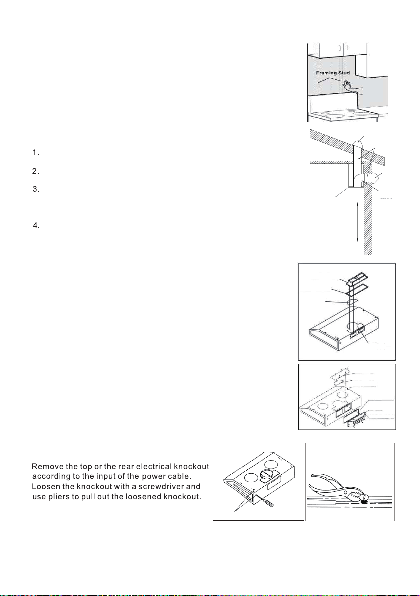
should be 26”~34”.
A
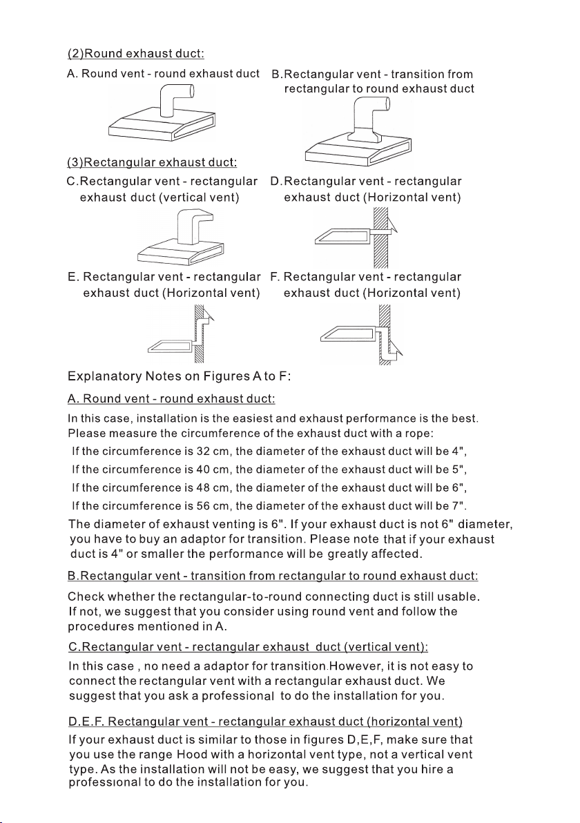
CAUTION duct air outside.
Do not vent exhaust air into spaces within walls or ceilingsor into attics, crawl spaces, or garages.
“CAUTION”-”For general ventilating use only.Do not use to exhaust hazardousb or explosive
materials and vapors.Take care when using cleaning agents or detergents.
Suitable for use in household cooking area. “
WARING
WARING
a) Use If you have questions,
contact the manufacturer.
b) Before service panel to
prevemt power from being switched on accidentally.
When the service disconnecting means cannot be locked, securely fasten a prominent warning
device, such as a tag, to the service panel.
c) Ins
per
inc
d) Su through the flue
drafting. Fo
stan
Protection Association and Air
C
e) When wiring and other hidden
utilities.
f ) D
g) This product may have sharp edges. Be careful to avoid cuts and abrasions during installation
or cleaning.
WARNING-To reduce the risk of a range top grease fire:
a) Clean ventilation fans frequently. G accum
b) Always turn hood on when c foods.
(i.e. Crepes Suzette, Cherries jubilee, Peppercorn Beff Flambe.)
c) Never leave surface units unattended at cause smoking and greasy
s
is used. Heat oils slowly on low or medium settings.
d) D
e) Us the surface element.
WARNING-To reduce the risk of injury to persons in the event of a range top grease fire, observe the
following:
a) Smother flames with or
metal tray, then turn off the burner.
b) Never pick up a flaming pan-y
c) Do not use water,
d) Use an
W
l distance between the cook-top and the range hood
To reduce the risk of fire or electric shock, Do not use this fan with any solid-state
speed control device.
To reduce the risk of fire. Electric shock, or injury to persons, observe the following:
turn
A
explosion will result.
Only if
and safety
11.
12.
13.
14.
WARNING-To reduce the risk o
Do not install less than 26 inches above cooking surface.
A replacement SBCFL lamp be type that complies with UL 1993.
You know how to operate it.
T
T
Y
-1-
10.