Salda VEGA 350 E Manual

Subject to technical modication
VEGA_P0102_AZ_0002
AIR SUPPLY UNITS
Installation and maintenance manual
VEGA 350 E
VEGA 700 E
VEGA 1100 E/W

2www.salda.lt
VEGA 350E/700E/1100E/1100W
Contents 2
Marking 3
Unpacking 3
Standard package of components 3
General information 4
Transportation and storage 4
Description 4
Safety precautions 5
Components 5
Operating conditions 5
Maintenance 6
Cover opening VEGA 350 E, VEGA 700 E 7
Cover opening VEGA 1100 E/W 8
Filter 9
Fan 9
Electrical heater 10
Water heater 11
Control box 11
Dimensions 12
Mounting 13
Start-up 13
Technical data 14
Components 16
Accessories 17
Automatic control 18
On/O air supply unit 18
Weekly calendar 18
Fan control 18
Electric heater control 18
Operation of VEGA 1100 W water heater protection
function 18
Informational and protection circuits of the unit 18
Air damper actuator control 19
Fault alarms on FELX control panel 19
Fault alarms on Stouch control panel 19
Modbus connection and control panel 19
ModBus type – RTU 15 19
Technical characteristics of supply air temperature
sensor 19
Labeling, characteristics of the controller RG1 and the
system components 21
Fault indication on control panel 21
VEGA 350E AC 1k electrical connection diagram 22
VEGA 350E AC 1k electrical connection diagram 23
EH 1.2 1f VEGA 350E electrical connection diagram 24
EH 2,4 1f VEGA 350E electrical connection diagram 25
EH 5,0 2f VEGA 350E electrical connection diagram 26
VEGA 700E/1100E AC electrical connection diagram 27
VEGA 700E/1100E AC electrical connection diagram 28
EH 2,4 1f VEGA 700E electrical connection diagram 29
EH 5,0 2f VEGA 700E electrical connection diagram 30
EH 9,0 3f VEGA 700E electrical connection diagram 31
EH 6,0 2f VEGA 1100E electrical connection diagram 32
EH 9,0 3f VEGA 1100E electrical connection diagram 33
EH 15,0 3f VEGA 1100E electrical connection diagram 34
Fan electrical connection diagram 35
VEGA AC W electrical connection diagram 36
VEGA AC W electrical connection diagram 37
Fan electrical connection diagram 38
Selection of power supply cable and security device 39
Inspection of the ventilation system 39
Improper operation and repair 39
Warranty 40
Notes 41
Maintenance Table 42

3
www.salda.lt
VEGA 350E/700E/1100E/1100W
200003025238
IV
PV
KE
PE
M
0.084 kW; 0.92 A; 230/50 V/Hz; ~1
0.085 kW; 0.93 A; 230/50 V/Hz; ~1
kW; A; 0 V/Hz; ~0
kW; A; 0 V/Hz; ~0
0.005 kW; 0.021 A; 24/50 V/Hz; ~-
0.17 kW; 1.87 A; IP-34
TOTAL:
gu072489 / 2014.03 www.salda.lt
1
3
4
5
2
6
200003025238
IV
PV
KE
PE
M
0.084 kW; 0.92 A; 230/50 V/Hz; ~1
0.085 kW; 0.93 A; 230/50 V/Hz; ~1
kW; A; 0 V/Hz; ~0
kW; A; 0 V/Hz; ~0
0.005 kW; 0.021 A; 24/50 V/Hz; ~-
0.17 kW; 1.87 A; IP-34
TOTAL:
gu072489 / 2014.03 www.salda.lt
1
3
4
5
2
6
PAVYZDYS
EXAPLE
PAVADINIMAS
TITLE
M
200003025238
IV
PV
KE
PE
M
0.084 kW; 0.92 A; 230/50 V/Hz; ~1
0.085 kW; 0.93 A; 230/50 V/Hz; ~1
kW; A; 0 V/Hz; ~0
kW; A; 0 V/Hz; ~0
0.005 kW; 0.021 A; 24/50 V/Hz; ~-
0.17 kW; 1.87 A; IP-34
TOTAL:
gu072489 / 2014.03 www.salda.lt
1
3
4
5
2
6
ESEMPIO
TITOLO
200003025238
IV
PV
KE
PE
M
0.084 kW; 0.92 A; 230/50 V/Hz; ~1
0.085 kW; 0.93 A; 230/50 V/Hz; ~1
kW; A; 0 V/Hz; ~0
kW; A; 0 V/Hz; ~0
0.005 kW; 0.021 A; 24/50 V/Hz; ~-
0.17 kW; 1.87 A; IP-34
TOTAL:
gu072489 / 2014.03 www.salda.lt
1
3
4
5
2
6
MUSTER
TITEL
200003025238
IV
PV
KE
PE
M
0.084 kW; 0.92 A; 230/50 V/Hz; ~1
0.085 kW; 0.93 A; 230/50 V/Hz; ~1
kW; A; 0 V/Hz; ~0
kW; A; 0 V/Hz; ~0
0.005 kW; 0.021 A; 24/50 V/Hz; ~-
0.17 kW; 1.87 A; IP-34
TOTAL:
gu072489 / 2014.03 www.salda.lt
1
3
4
5
2
6
ПPИМEP
НАЗВАНИЕ
1 2 3 4
Stick here
Stick the auxiliary label on the unit (on an easily accessible place) or
on the dashed place of a technical manual in order to keep the important
information about the unit.
1 – Logo
2 – Internal usage code
3 – Brand name
4 – Technical data
5 – Unit number and date
6 – Web address
Standard package includes (without optional accessories):
1. Amortization pads with hanging bracket - 4 pcs. (VEGA
350E/700E), 6 pcs. (VEGA 1100 E/W);
2. Screws M5x16 DIN 7985, spring washers 5 DIN 127, washers 5
DIN 440R - 8 sets (VEGA 350E/700E), 12 sets (VEGA 1100 E/W);
3. Supply air sensor TJ - 1 pcs.
4. Outdoor air sensor TL - 1 pcs. (VEGA 1100W)

4www.salda.lt
VEGA 350E/700E/1100E/1100W
Air supply unit VEGA is specially designed for ventilation of the premises with suspended height installation possibilities. Units VEGA comply ErP 2016
norms and stand out with the best possible air tightness class in the market. Supply air ow from 350 to 1000 m3/h.
Easy installation:
• 6 possible mounting positions;
• extremely low height - space saving design.
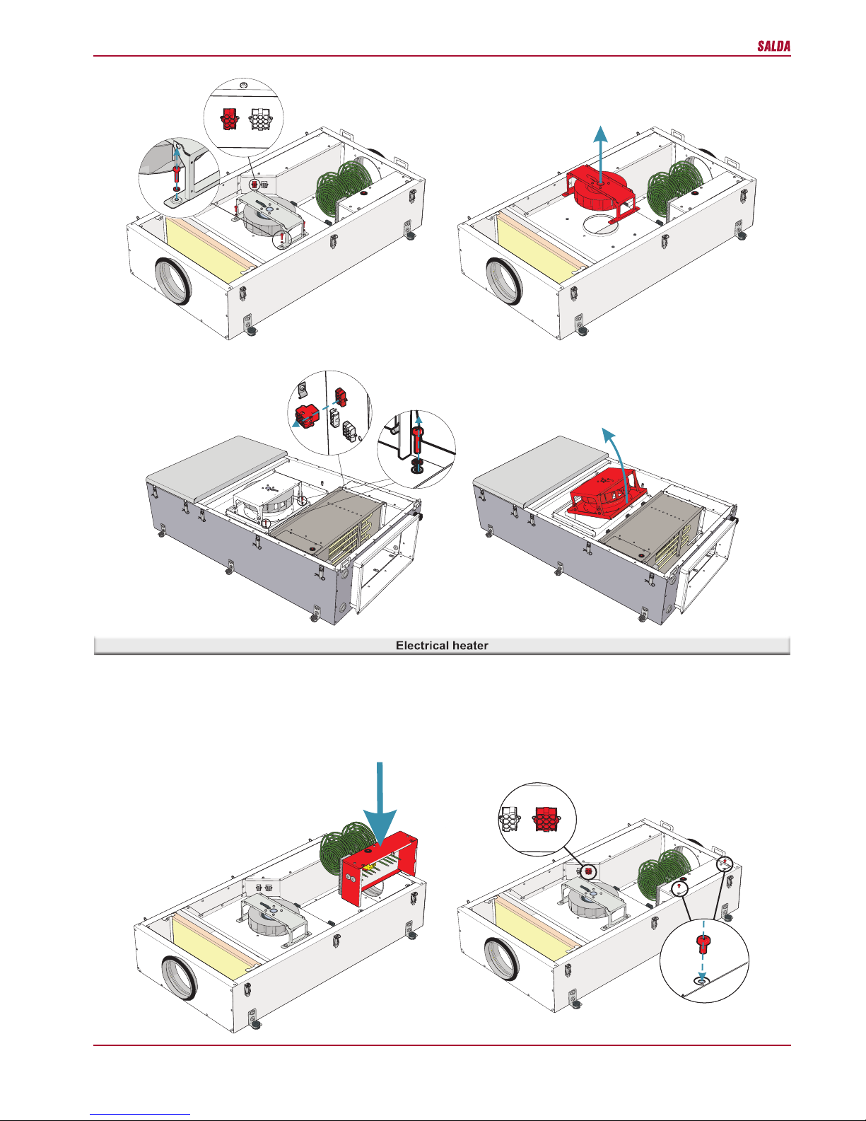
Simple service:
• qualitative and ergonomic design (integrated control box);
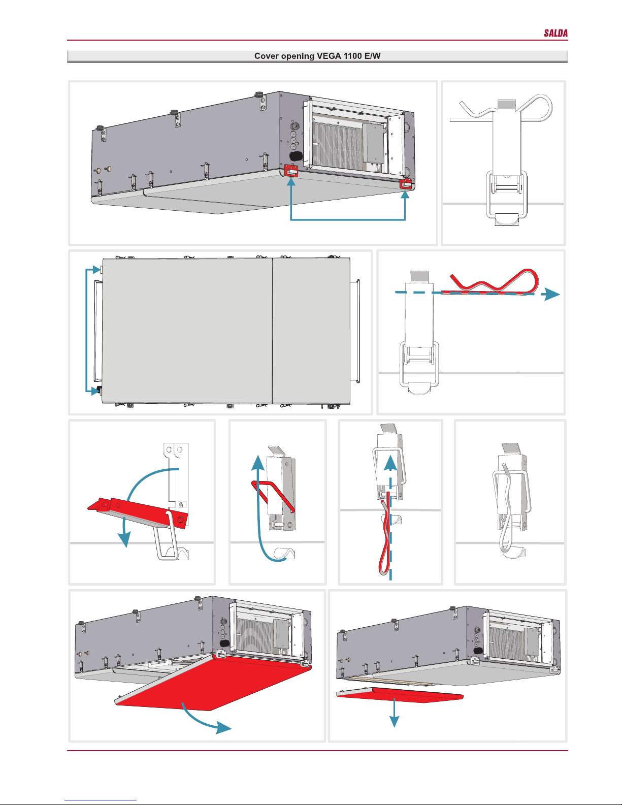
• safe and easy doors opening for lter replacement
Economical usage:
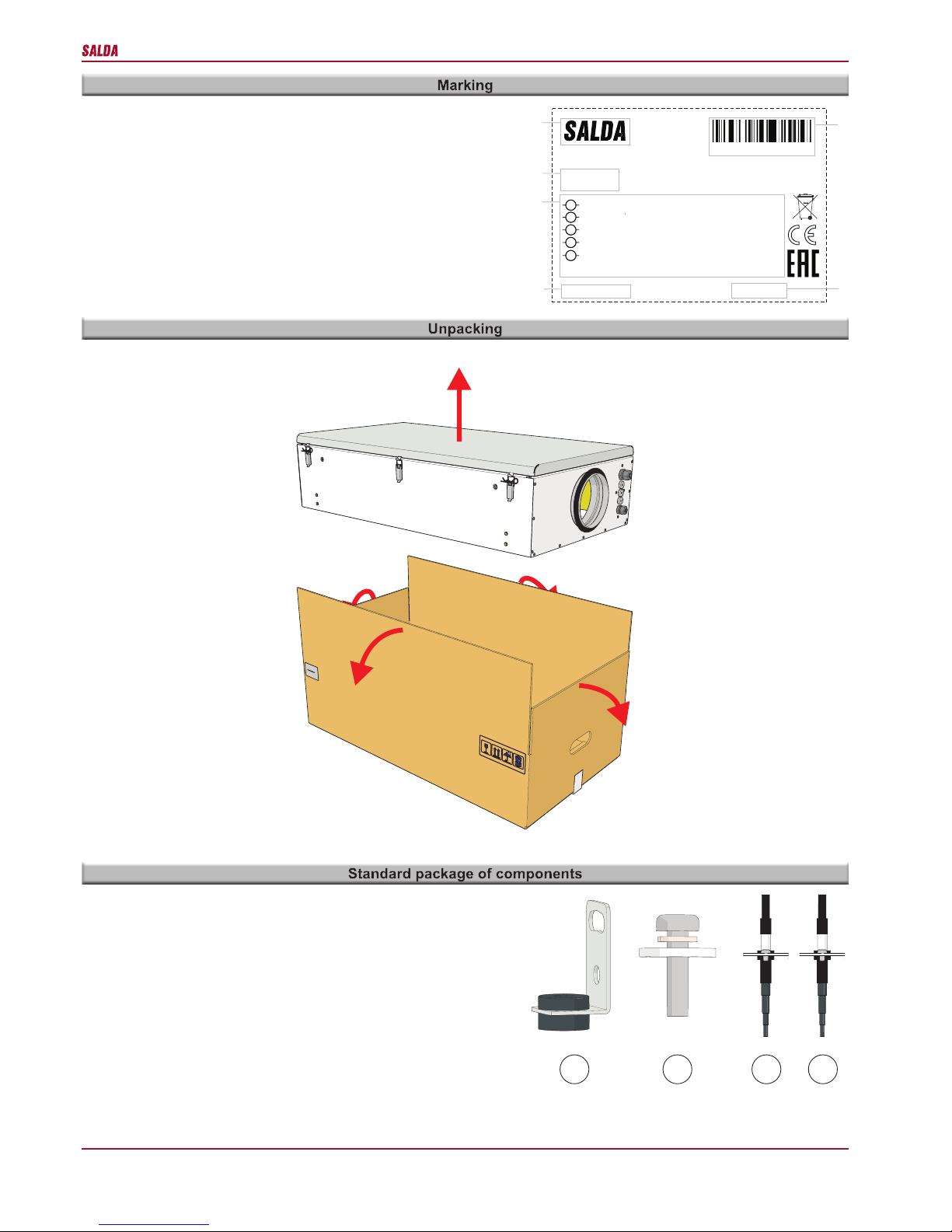
• All units are packed in the factory to withstand regular conditions of transportation.
• Upon unpacking, check the unit for any damages caused during transportation. It is forbidden to install damaged units!!!
• The package is only a protection means!
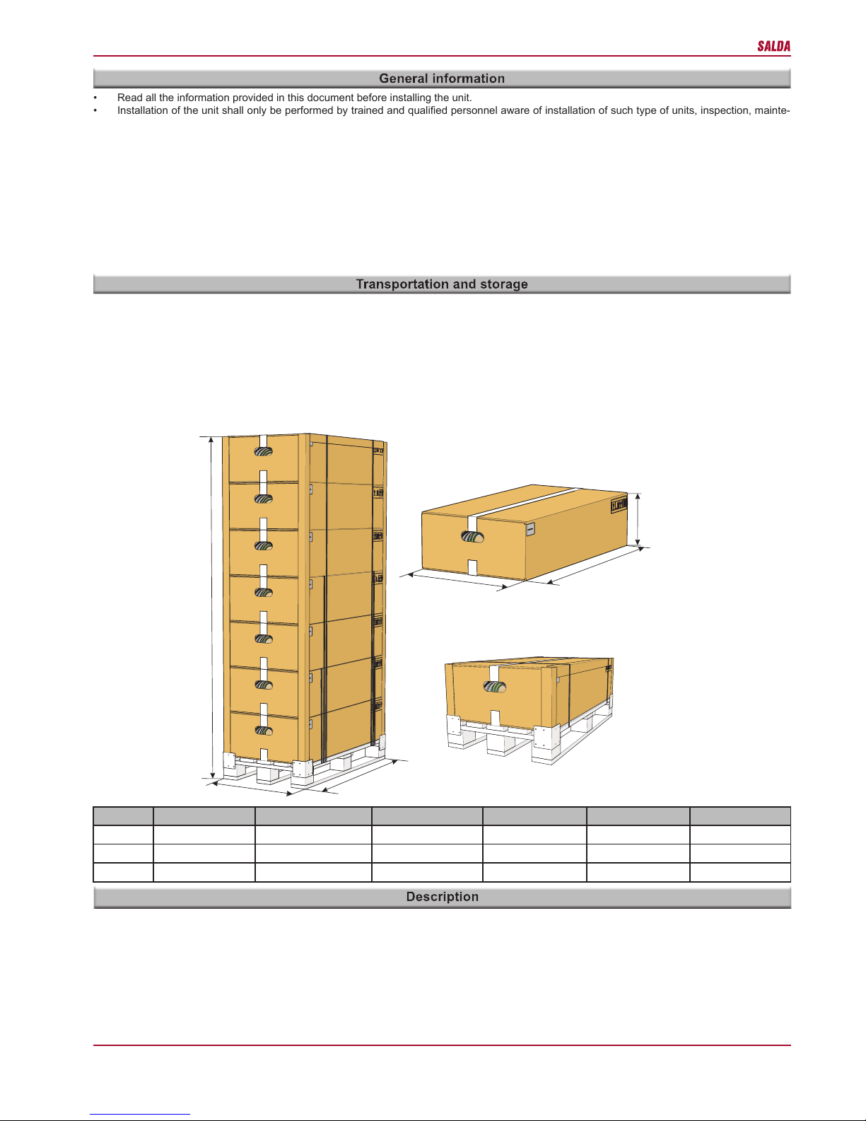
• At unloading and storing the units, use suitable lifting equipment to avoid damages and injuries. Do not lift units by holding on power supply
cables, connection boxes, air intake or discharge anges. Avoid hits and shock overloads. Before installation units shall be stored in a dry room
with the relative air humidity not exceeding 70% (at +20°C) and with the average ambient temperature ranging between 0°C and +30°C. The
place of storage shall be protected against dirt and water.
• During transportation and storage of the units, the connection anges must be in horizontal position.
• The storage is not recommended for a period longer than one year. In case of storage longer than one year, it is necessary to check free rotation
of bearings before installation (turn the impeller by hand).
• Read all the information provided in this document before installing the unit.
• Installation of the unit shall only be performed by trained and qualied personnel aware of installation of such type of units, inspection, mainte-
nance and tools required for installation works.
• While installing the unit, follow the international and national requirements of mechanical and electrotechnical safety of the country where the
product will be installed and used.
• If the provided information is unclear or any doubts arise regarding safe installation and operation, please contact the manufacturer or its repre-
sentative.
• The unit shall be operated only under the conditions listed below.
• It is strictly forbidden to use the unit for non-designed purposes or in contradiction to the specied working conditions without written permission
of the manufacturer or its representative.
• The manufacturer or its representative shall be notied about any fault, including description of the fault and data specied on the product’s label.
• Any repair or dismantle of the unit in case of fault is forbidden without previous written permission of the manufacturer or its representative.
• Dismantling, repair or modication of the unit shall be performed only upon prior written consent of the manufacturer or its representative.
• The end user shall ensure that the unit is suitable for environmental conditions before ordering and installing the unit.
W2
L2
H2
H1
L1
W1
VEGA L1, mm L2, mm W1, mm W2, mm H1, mm H2,mm
350 E 1090 1070 600 580 2150 287
700 E 1295 1275 600 580 2165 315
1100 E/W 1440 1415 840 821 2400 356

5
www.salda.lt
VEGA 350E/700E/1100E/1100W
• Unit is designed for indoor use only at temperature between 0°C and +40°C and relative humidity not exceeding 70%.
• It is forbidden to use the units in potentially explosive environment.
• Unit is designed for ventilation and conditioning systems to supply to a room only clean air (free of chemical compounds causing metal corrosion,
of substances aggressive to zinc, plastic and rubber, and of particles of solid, adhesive and bred materials).
• Minimum and maximum permissible air ow temperature between -20°C and +40°C.
• Maximum outside humidity 90%.
• Do not use this unit for purposes other than those provided in its design.
• Do not dismantle and modify the unit. Such actions can cause mechanical fault or even injury.
• Use special working clothes when installing and maintaining the unit. Be careful – angles and edges of the unit and its components can be sharp
and cause injuries.
• Being near the unit, do not wear free streaming clothes that could be sucked into the operating fan.
• All products packed in the factory are not prepared for eventual operation. The units can be used only by connecting them to air ducts or by
installing protection grating in air intake and discharge openings.
• Do not put ngers or any other objects into protection grating of air intake and discharge or into connected air duct. In case any foreign body get
into the unit, disconnect the power supply source immediately. Before removal of foreign body, make sure that any mechanical movement in the
unit has stopped. In addition, make sure that the accidental switching-on of the unit is impossible.
• Avoid direct contact with the ow of supplied and extracted air.
• Do not connect the unit to the mains other than indicated in the manufacturer’s label on the casing of the unit.
• Never use a damaged power supply cable.
• Never touch with wet hands the power supply cables connected to the mains.
• Never dip extension cords and plugs in water.
• Do not install and use the unit on uneven surfaces or other unstable planes.
• Never use this unit in the environment conducive to explosion and containing any aggressive materials.
10
22
14 1
21
18 19 20
6
1 2 34578
9
10
11 12 13
14
15 16 17 13
11 15
19
Supply air outdoor air
1. Cover holder - 2 pcs.
2. Cable holder
3. Heater button
4. Heating element
5. Electric heater (ordered and installed by the user) / or integrated water
heater for VEGA 1100W
6. Wire holder
7. Impeller holder
8. Filter G4
9. Filter retainer – 2 pcs.
10. Flange- 2 pcs.
11. Amortization pads with hanging brackets - 4 pcs. (VEGA 350E/700E),
6 pcs. (VEGA 1100 E/W)
12. GD collar- 2 pcs. (only VEGA 1100 E/W)
13. Casing
14. Cover fastening pins - 6 pcs. (VEGA 350E/700E), 10 pcs. (VEGA 1100
E/W)
15. Power supply cable collar
16. Control box
17. Heater and fan plug sockets
18. Fan
19. pressure switch - 2 pcs. (only VEGA 1100 E/W)
20. Control panel cable collar
21. Other collars
22. Cover
• complies with ErP 2016 directive norms;
• the highest possible tightness class A1/L1.
Simple design:
• fan with backward curved blades;
• panel G4 class lter;
• integrated electric heater in all models as an option;
• integrated water heater in models from size 1100 as an option.

6www.salda.lt
VEGA 350E/700E/1100E/1100W
• The maintenance works for ventilation unit shall be performed 3–4 times a year.
• Before start of maintenance works ENSURE THAT the unit is disconnected from the voltage and wait until the fan rotation stops and the heating
elements cool down.
CAUTION: Operation of the unit is designed so that the supply voltage is supplied to the fan for about 30 seconds after switching o the unit with the
remote controller, in order to cool down the heating elements.
• The maintenance works shall be performed by following the above safety rules.
Opening of the cover:
1. The cover is closed with the clips that are fastened with the pins to avoid spontaneous opening (b);
2. The cover has holders (a);
3. The cover has to be opened by retaining a certain order (c);
4. Firstly remove the pin (d);
5. Unfasten the clip (e);
6. Press the upper part of the clip and the hook to the casing (f) and fasten with the same pin as shown in pictures (g, h);
7. Open the cover and keep it hanging on the holders;
8. Retain the reverse order when closing the cover.

7
www.salda.lt
VEGA 350E/700E/1100E/1100W
Pav. 8
d
efgh
c
1
24
3
6
5
ab
i

8www.salda.lt
VEGA 350E/700E/1100E/1100W
d
efgh
c
ab
i
1
2
3
4
5
6
1
24
3
j

9
www.salda.lt
VEGA 350E/700E/1100E/1100W
Change the supply air lter after the alert of the control system.
The alert about lter contamination is active if the working hours of the unit till the lter change notice are set in Flex control panel.
• Fan must be inspected and cleaned at least once a year.
• High-eciency bearings are used in the motor. The bearings do not have to be lubricated during the entire operational period of the motor.
• Disconnect the fan from the unit.
• Carefully inspect the fan impeller for accumulated dust and other materials which could aect the balance of impeller. The misbalanced impeller
can cause vibration and premature wear of motor bearings.
• Clean the impeller and the interior of casing using mild, non-aggressive and non-corrosive detergent and water.
• For cleaning the impeller do not use high-pressure devices, cleaners, sharp tools or aggressive solvents which could scratch or damage the
impeller.
• When cleaning the impeller, do not immerse the motor in a liquid.
• Ensure that balancing weights of the impeller are in appropriate position.
• Ensure that the casing does not block the impeller.
• Allow the impeller to dry before mounting the fan.
• Mount the fan back to the unit.
• If the fan does not switch on after the maintenance works, contact the manufacturer.
12
12
VEGA 350 E, VEGA 700 E
VEGA 1100 E/W

10 www.salda.lt
VEGA 350E/700E/1100E/1100W
• Electrical heaters do not require additional servicing.
• The heater has 2 thermal protections: automatic restore which is activated at +50°C and manual restore which is activated at +100°C.
• If the manual restore protection is activated, disconnect the unit from the power supply source. Wait until the heating elements cool down and the
fan rotation stops. Press the Reset button and start the unit.
• The unit doesn’t work without electrical heater. It is necessary to choose and install electric heater according to the recommendations (see
“Selection of the power supply cable and safety device”)
x32 x29
12
12
x32 x29
2
1
VEGA 350 E, VEGA 700 E
VEGA 1100 E/W
VEGA 350 E, VEGA 700 E

11
www.salda.lt
VEGA 350E/700E/1100E/1100W
• It is not necessary to take o the screw that fastens the control box during the installation, it is enough to unfasten it a little.
23
1
VEGA 1100 E
VEGA 350 E, VEGA 700 E
12
VEGA 1100 W
12
- It is foreseen to connect 0-10 V actuator and circulation pump to control box for water heater control.
- Three anti-frost protections of water heater are used: outdoor air sensor, return water temperature sensor, air ow thermostat behind water heater.

12 www.salda.lt
VEGA 350E/700E/1100E/1100W
VEGA L1, mm L2, mm L3, mm W1, mm W2, mm W3, mm H1, mm H2,mm ø D,mm
350 E 1000 1060 825 578 606 268 125 250 160
700 E 1200 1260 1025 578 606 268 145 300 200
VEGA L1, mm L2, mm L3, mm W1, mm W2, mm W3, mm H1, mm H2,mm
1100 E/W 1300 1400 554 807 835 500 250 340
123
VEGA 1100 E/W

13
www.salda.lt
VEGA 350E/700E/1100E/1100W
VEGA L1, mm L2, mm L3, mm W1, mm W2, mm W3, mm H1, mm H2,mm
1100 E/W 1300 1400 554 807 835 500 250 340
180o
Mounting positions
• Operation start-up of the unit shall be performed only by trained and qualied personnel.
• The assembly is ready for work after the voltage, remote controller, selected accessories are connected and the ventilation unit is connected to
the air duct system.
• Before start-up, make sure that power supply circuit corresponds to the specication indicated in the label.
• Before start-up, make sure that the unit is connected to the mains in accordance with the wiring diagram shown in this document and under the
connection cover of automatic control board.
• Before start-up of the fan, make sure that the above instructions of safety and installation are applied.
• Upon start-up of the unit, make sure that the motor rotates evenly, without vibration and outside noise.
• Upon start-up of the unit, make sure that the air ow generated by the unit matches the direction of air indicated on the casing.
• MAKE SURE that the air intake damper opens and closes correctly.
• The current used by the unit shall be tested for compliance with the maximum allowed current indicated in this document.
• Using the remote controller select the necessary fan rotation speed and supply air temperature.
- Installing should only be performed by qualied and trained sta.
It is recommended to x the air supply unit using supplementary brackets.
- Mount the unit on safe and rm base.
- Connecting the duct system refer to air ow labels.
Standard package includes (without optional accessories):
1. Amortization pads with hanging bracket - 4 pcs. (VEGA 350E/700E), 6 pcs. (VEGA 1100 E/W);
2. Screws M5x16 DIN 7985, spring washers 5 DIN 127, washers 5 DIN 440R - 8 sets (VEGA 350E/700E), 12 sets (VEGA 1100 E/W);
3. Supply air sensor TJ - 1 pcs.
4. Outdoor air sensor TL - 1 pcs. (VEGA 1100W)

14 www.salda.lt
VEGA 350E/700E/1100E/1100W
VEGA 350
EH
1.2 1f
EH
2.4 1f
EH
5.0 2f
Heater* phase/voltage [50Hz/VAC] ~1/230 ~1/230 ~2/400
power consumption [kW] 1,2 2,4 5,0
weight [kg] 1,5 2 3
Fan phase/voltage [50Hz/VAC] ~1/230
power/current [kW/A] 0,07/0,30
speed [min-1]2800
protection class IP 44
Total power consumption (power/cur-
rent) [kW/A] 1,27 /
5,54
2,47 /
10,76
5,07 /
12,69
Insulation of walls [mm] 30
Color RAL balta (9016)
Weight (net, without packing) [kg] 33
Automatic control +
VEGA 700
EH
2.4 1f
EH
5.0 2f
EH
9.0 3f
Heater* phase/voltage [50Hz/VAC] ~1/230 ~2/400 ~3/400
power consumption [kW] 2,4 5,0 9,0
weight [kg] 3,5 4 9
Fan phase/voltage [50Hz/VAC] ~1/230
power/current [kW/A] 0,14/0,60
speed [min-1]2659
protection class IP 44
Total power consumption (power/cur-
rent) [kW/A] 2,54 /
11,04
5,14 /
12,85
9,14 /
13,19
Insulation of walls [mm] 30
Color RAL balta (9016)
Weight (net, without packing) [kg] 42
Automatic control +
VEGA 1100
EH
6.0 2f
EH
9.0 3f
EH
15.0 3f
Heater* phase/voltage [50Hz/VAC] ~2/400 ~3/400 ~3/400
power consump-
tion [kW] 6,0 9,0 15,0
weight [kg] 6,89 6,80 11,80
Fan phase/voltage [50Hz/VAC] ~1/230
power/current [kW/A] 0,28/1,25
speed [min-1]2762
protection class IP 44
Total power consumption (power/cur-
rent) [kW/A] 6,28 /
27,30
9,28 /
13,40
15,28 /
22,00
Insulation of walls [mm] 30
Color RAL pilka (7040)
Weight (net, without packing) [kg] 66
Automatic control +
Subject to technical modication.
* heater supplied separately.
0,000
0,020
0,040
0,060
0,080
0,100
0,120
0,140
0,160
0
50
100
150
200
250
300
350
400
0 100 200 300 400 500 600
P, KW
∆P, PA
QV, M3/H
140V + 1,2 kW
1
170V + 1,2 kW
2
230V + 1,2 kW
3
230V + 2,4 kW
4
230V + 5 kW
5
P1, kW
6
P2, kW
7
P3, kW
8
P4, kW
9
P5, kW
10
12345
8
7
6910
ρ=1,2 kg/m
3
140V + 2,4 kW
1
170V + 2,4 kW
2
230V + 2,4 kW
3
230V + 5 kW
4
230V + 9 kW
5
P1, kW
6
P2, kW
7
P3, kW
8
P4, kW
9
P5, kW
10
∆P, PA
P, KW
QV, M3/H
12345
8
7
6910
VEGA 350 E
VEGA 700 E
0,000
0,050
0,100
0,150
0,200
0,250
0,300
0
100
200
300
400
500
600
700
800
0 200 400 600 800 1000 1200 1400
ρ=1,2 kg/m
3
∆P, PA
P, KW
QV M3/H
VEGA 1100 E
v3 + 6 kW
1
v2 + 6 kW
2
v1 + 6 kW
3
v3 + 9 kW
4
v3 + 15 kW
5
P1, kW
6
P2, kW
7
P3, kW
8
P4, kW
9
P5, kW
10
VEGA 1100 W
1
2
3
4
5
6910
8
7
0,000
0,050
0,100
0,150
0,200
0,250
0,300
0
100
200
300
400
500
600
700
800
0 200 400 600 800 1000 1200 1400
v1 (max) v2 (mid) v3 (min) P1, kW P2, kW P3, kW
ρ=1,2 kg/m
3
∆P, PA
P, KW
QV, M3/H
123
4
56
1
2
3
4
6
5

15
www.salda.lt
VEGA 350E/700E/1100E/1100W
Subject to technical modication.
VEGA 350 E VEGA 700 E VEGA 1100 E/W
Air lter class G4 G4 G4
width L [mm] 469 469 700
height H [mm] 180 230 270
depth W [mm] 25 25 25
model MPL MPL MPL
w
VEGA 1100 W
Water heater power [kW] 16,11
water temperature [Co]+80/+60
water ow rate [l/s] 0,2
water pressure drop [kPa] 9,5
connection diameter DN 1/2”
Fan phase/voltage [50Hz/VAC] ~1
power/current [kW/A] 0,29/1,26
speed [min-1]2762
protection class IP 44
Total power consumption (power/current) [kW/A] 0,29/1,26
Insulation of walls [mm] 30
Color RAL gray (7040)
Weight (net, with water heater) [kg] 73
Automatic control +
0,000
0,020
0,040
0,060
0,080
0,100
0,120
0,140
0,160
0
50
100
150
200
250
300
350
400
0 100 200 300 400 500 600
P, KW
∆P, PA
QV, M3/H
140V + 1,2 kW
1
170V + 1,2 kW
2
230V + 1,2 kW
3
230V + 2,4 kW
4
230V + 5 kW
5
P1, kW
6
P2, kW
7
P3, kW
8
P4, kW
9
P5, kW
10
12345
8
7
6910
ρ=1,2 kg/m
3
140V + 2,4 kW
1
170V + 2,4 kW
2
230V + 2,4 kW
3
230V + 5 kW
4
230V + 9 kW
5
P1, kW
6
P2, kW
7
P3, kW
8
P4, kW
9
P5, kW
10
∆P, PA
P, KW
QV, M3/H
12345
8
7
6910
VEGA 350 E
VEGA 700 E
0,000
0,050
0,100
0,150
0,200
0,250
0,300
0
100
200
300
400
500
600
700
800
0 200 400 600 800 1000 1200 1400
ρ=1,2 kg/m
3
∆P, PA
P, KW
QV M3/H
VEGA 1100 E
v3 + 6 kW
1
v2 + 6 kW
2
v1 + 6 kW
3
v3 + 9 kW
4
v3 + 15 kW
5
P1, kW
6
P2, kW
7
P3, kW
8
P4, kW
9
P5, kW
10
VEGA 1100 W
1
2
3
4
5
6910
8
7
0,000
0,050
0,100
0,150
0,200
0,250
0,300
0
100
200
300
400
500
600
700
800
0 200 400 600 800 1000 1200 1400
v1 (max) v2 (mid) v3 (min) P1, kW P2, kW P3, kW
ρ=1,2 kg/m
3
∆P, PA
P, KW
QV, M3/H
123
4
56
1
2
3
4
6
5

16 www.salda.lt
VEGA 350E/700E/1100E/1100W
PV supply air fan
KE* electrical heater (supplied separately)
PF lter for outdoor air
TJ air temperature sensor
PS** external dierential pressure switch (optional)
*
*
VEGA 350 E, VEGA 700 E
VEGA 1100 E
PS**
VEGA 1100 W
TL
PS**
KV
SV1
M
Outdoor air Supply air
Supply air
Outdoor air
KV water heater
M Circulation pump of the heater
TL outdoor air temperature sensor
SV1 Heater’s valve actuator

17
www.salda.lt
VEGA 350E/700E/1100E/1100W
AKS
Silencer
RSK
Back draft shutter RSK
CM230
Actuator for damper
EH VEGA 1100 E
Electric heater
SSB
Electromotoric actuator
(VEGA 1100W)
PS
Pressure sensor
VEGA 350 E
EH 1.2 1f VEGA 350 ZESVEGA001
EH 2.4 1f VEGA 350 ZESVEGA002
EH 5.0 2f VEGA 350 ZESVEGA003
Remote control panel Stouch PRGPU051
Remote control panel FLEX PRGPU015
Filter MPL (469x180x25) G4 ZFEPF118
Actuator for damper CM230-1-F-L ZAKP0027
Shut-o damper SKG 160 GSKSKG003
Back draft shutter RSK 160 GSKRSK003
Mounting clamp AP 160 GAPAP004
Silencer AKS 160 - 9 GSOAKS006
VEGA 1100 E
EH 6.0 2f VEGA 1100 ZESVEGA010
EH 9.0 3f VEGA 1100 ZESVEGA011
EH 15.0 3f VEGA 1100 ZESVEGA012
Remote control panel Stouch PRGPU051
Remote control panel FLEX PRGPU015
Filter MPL (700X270X25) G4 ZFEPF130
Actuator for damper CM230-1-F-L ZAKP0027
Back draft shutter SSK 500-250 GSKSSK013
Silencer SKS 50-25 GSOSKS003
Pressure sensor PS600B ZAKJT003
VEGA 700 E
EH 2.4 1f VEGA 700 ZESVEGA004
EH 5.0 2f VEGA 700 ZESVEGA005
EH 9.0 3f VEGA 700 ZESVEGA006
Remote control panel Stouch PRGPU051
Remote control panel FLEX PRGPU015
Filter MPL (469x230x25) G4 ZFEPF123
Actuator for damper CM230-1-F-L ZAKP0027
Shut-o damper SKG 200 GSKSKG004
Back draft shutter RSK 200 GSKRSK004
Mounting clamp AP 200 GAPAP005
Silencer AKS 200 - 9 GSOAKS008
VEGA 1100 W
Remote control panel Stouch PRGPU051
Remote control panel FLEX PRGPU015
Filter MPL (700X270X25) G4 ZFEPF130
Actuator for damper TF230 ZAKP0063
Back draft shutter SSK 500-250 GSKSSK013
Silencer SKS 50-25 GSOSKS003
Pressure sensor PS600B ZAKJT003
Electromotoric actuator SSB61 200Nm PRGP005
Flex
Remote control panel
Stouch
Remote control panel
MPL
Filter
SSK
Dumper
EH VEGA 350E/700E
Electric heater
SKS
Silencer
TF230
Actuator for damper
SKG
Damper
AP
Mounting clamp
RMG
Mixing point
(VEGA 1100W)

18 www.salda.lt
VEGA 350E/700E/1100E/1100W
When the unit is being turned on, air damper opens for 90 seconds and afterwards the fan turns on. The controller measures supply air temperature
once a second and, if necessary, activates the heater so that supply air temperature is as close as possible to the desired set temperature. If the user
changes fan speed with the remote control panel, the controller changes fan speed and according to that adjusts the operation of the heater.
When the unit is being turned o, the fan runs for 60 seconds at lowest speed to cool the heater and afterwards turns o the fan and closes air damper.
Function of the calendar is supported by the remote control panel, so if you want to have this function, you should obtain remote control panel FLEX.
Calendar enables to set up to 8 events a day. Each event has an indicated its operation time, fan speed, and the desired supply air temperature. It is
possible to set the same events for all working days, weekends or an entire week.
When an event is being created, remote control panel once a minute checks if there are any other commands for that period. When the remote control
panel detects a command, it sends speed and temperature settings to the controller.
Regardless calendar settings the user can manually (with remote control panel) change fan speed and desired temperature at any time.
The controller changes motor speed with autotransformer by changing the voltage supplied to the motor. There are 3 xed motor speeds and one
additional - zero speed, which is used to stop the unit according to calendar or Modbus setting.
When fan speed is being changed by the remote control panel of Modbus, motor stops and after a few seconds switches to a dierent speed. Such a
delay is necessary to protect the motor from overloading.
1. FAN MOTOR PROTECTION
It is normally closed contacts A4, GND in connection X1. Contacts are for the connection of engine thermocontacts. When thermocontacts interrupts
the circuit, the controller displays an error A4 and stops the system. The same error A4 can be triggered by thermocontacts of engine transformer. If
the transformer’s temperature reaches 70°C or more, the controller responds the same: an error A4 occurs and stops the system.
2. HEATERS OVERHEAT PROTECTION
Control box has a potential free normally closed contacts A6, GND in connection X1. Input gives a signal about active electric heater protection. When
the circuit is interrupted, the controller displays an error A6 and stops the system.
3. OUTPUT FOR EXTERNAL ALARM
It is potential free normally closed contacts A1, GND in connection X1. Contacts are for the reception of the signal of an external alarm. Most often,
these contacts are connected to the re safety system. When the circuit is interrupted, the controller displays alarm A1 and stops the system.
4. FOR THE PRESSURE RELAYS OF THE FILTER
It is normally opened potential-free contacts Filter, GND in connection X1. Contacts are used to receive a signal from the pressure rely. When pressure
relay is activated, the circuit between the contacts is being closed. If the circuit remains closed for 60 sec., contaminated lter alarm (FIL) is displayed.
The system is not stopped.
5. FOR THE SUPPLIED AIR TEMPERATURE SENSOR
Contacts Ain1 are provided for the connection of supply air temperature sensor, GND in connection X1. Supply air temperature sensor’s technical
characteristics are provided in the table below.
Controller controls electric heater by PWM control signal. This control method allows consistent regulation of the supply air temperature, without big
temperature uctuations. Electric heaters are not included in standard package of supply units VEGA. Air supply units can control single or a two-
phase electric heaters.
These heaters can respectively be ordered for the units:
EH 1.2 1f VEGA 350 ZESVEGA001 EH 2.4 1f VEGA 700 ZESVEGA004 EH 6.0 2f VEGA 1100 ZESVEGA010
EH 2.4 1f VEGA 350 ZESVEGA002 EH 5.0 2f VEGA 700 ZESVEGA005 EH 9.0 3f VEGA 1100 ZESVEGA011
EH 5.0 2f VEGA 350 ZESVEGA003 EH 9.0 3f VEGA 700 ZESVEGA006 EH 15.0 3f VEGA 1100 ZESVEGA012
Controller version Ventik-W has a water heater frost protection function. This feature works dierently when the controller is in normal mode and when
in standby mode.
Protection in standby mode:
When active standby mode, the controller every second measures the air temperature and the return water temperature.
If the air temperature is higher than 0 oC, protection is not activated.
If the air temperature drops to or below 0 oC, the controller switches on the circulation pump and opens the three-way valve so that the return water
temperature will be 25 oC.
Protection in normal operation:
When the controller is in normal mode, the heater frost protection uses two parameters:
1. TAL critical return water temperature (-10 oC ... + 5 oC).
2. PBAND frost protection working zone (5 oC ... 10 oC).
TAL is a critical return water temperature. If the water temperature drops to or below this threshold, the controller stop the system and displays error A2.
PBAND enables the system react in water temperature drop, before error A2.
TAL + PBAND = TP
. TPis the lowest temperature of the water when the three-way valve and pump control is carried out under the normal supply air
temperature control mechanism. When run this mechanism, the controller is working so that the supply air temperature is as close as possible to the
set-point temperature.
If the water temperature drops below the TA, then higher priority have frost protection mechanism.

19
www.salda.lt
VEGA 350E/700E/1100E/1100W
Technical characteristics of supply air temperature sensor
Thermister NTC10K (10@25 oC; β = 3250÷3300K)
Measuring range -40…120 oC
Measurement accuracy, % ±1
RS485 connection X12 is used to connect Modbus;
(See. Flex technical manual II-6-6.2).
Meanings of X12 connections:
Parameter Possible values Set value
Device address 1-247 1
Connection speed 19200 19200
Parity EVEN EVEN
Stop bit 1 1
ModBus type – RTU, MB slave addres – 1.
Port settings: RS485, 19200bps, 1STOP, PARITY-NONE
Remote control don’t support MB protocol, not connect to MB line.
Data address from 0x00
The controller also responds to command 11h (slave id) and returns a response EKR-KE / Ver.1.4 or similar. Slave device is connected to the system.
Table includes Modbus parameters of the controller.
4 3 2 1
1 +24V
2 485 B
3 485 A
4 GND
X12 connection is used for communication with the remote control panel. The same connection is used for Modbus communication. This means that
the system can be simultaneously controlled by remote control panel or Modbus commands. Controller detects if the device (remote control panel
or Modbus) is connected to the connection X12. When the remote control panel is connected to the connection X12 the controller recognizes it and
starts constant checking the connection with the remote control panel. If there is no communication for 10 seconds, the controller stops the system
and shows the NC error.
When the controller is connected Modbus device, the controller recognizes it after the rst Modbus command. When the controller is connected Mod-
bus device, then within 10 seconds after the controller. After the last command a brake system.
A.01 Fan fault
A.02 Supply air temperature sensor fault
A.03 Return water temperature sensor fault
A.04 Outdoor air temperature sensor fault
A.05 Fire protection activated
A.06 Cold spell (exchanger). Tsupply temp. less than (Tset-10’C) alarm (A2)
A.07 Fan overheat. Alarm from A4 input (A4)
A.08 Any sensor fail alarm
A.09 Critical return water temper. alarm (A5)
A.10 Low voltage alarm (A7)
A.11 Overheat. Alarm from A6 input (A6)
A.12 Clogged lters
A.13 Overheat. Tsupply temp. higher than 40 ‘C alarm (A6)
Fault alarms on FELX control panelFault alarms on FELX control panel
Look for fault alarm list in FLEX technical manual.
When the controller is turned on for 90s it is opening the air damper and then starts the operation. When the controller is turned o, the air damper is
closed.
Contacts (N, L and Supply) in connection X13 are foreseen to connect air damper actuator. 230VAC voltage always is in contact L. When the control-
ler gives the command to open air damper, 230VAC voltage occurs in contact “Supply”. When the controller gives a command to close air damper,
voltage is switched o in contact “Supply”.

20 www.salda.lt
VEGA 350E/700E/1100E/1100W
* - default value
EKR-KRE:150202 added Holding register „time o“
Name ModBus function R/W
Data
address
(dec)
Data
address
(hex)
Description Value
0x....) Coils Read - 01h, Write – 05h, 0Fh ( Present value, Unsigned Word )
Fire alarm Coils R 1 0x01 Alarm from A1 input (A1) 1-active, 0-passive
Filter Coils R 2 0x02 Info from Filter input 1-active, 0-passive
Fan overheat Coils R 3 0x03 Alarm from A4 input (A4) 1-active, 0-passive
LowPower Coils R 5 0x05 Low voltage alarm (A7) 1-active, 0-passive
T limit Coils R 8 0x08 Supply air temperature sensor alarm 1-active, 0-passive
Reset Coils W 18 0x12 System restart Read =0
Overheat Coils R 44 0x2C Alarm from A6 input (A6) 1-active, 0-passive
(1x....) Discrete Read – 02h ( Present value, Unsigned Word )
Tsupplay Discrete R 2 0x02 Supply air temperature sensor alarm 1-active, 0-passive
Twater Discrete R 4 0x04 Return water temperature sensor alarm 1-active, 0-passive
Toutdoor Discrete R 5 0x05 Outdoor air temperature sensor alarm 1-active, 0-passive
Fire alarm Discrete R 9 0x09 Alarm from A1 input (A1) 1-active, 0-passive
Coldspell (ex-
changer) Discrete R 10 0x0A Tsupplytemp.lessthan(Tset-10’C)alarm (A2) 1-active, 0-passive
Fan overheat Discrete R 12 0x0C Alarm from A4 input (A4) 1-active, 0-passive
Sensors Discrete R 13 0x0D Any sensor fail alarm 1-active, 0-passive
Water Discrete R 18 0x12 Critical return water temper. alarm (A5) 1-active, 0-passive
LowPower Discrete R 19 0x13 Low voltage alarm (A7) 1-active, 0-passive
Overheat Discrete R 22 0x16 Alarm from A6 input (A6) 1-active, 0-passive
Filter Discrete R 23 0x17 Info from Filter input 1-active, 0-passive
Supply Discrete R 24 0x18 Air supply valve output active 1-active, 0-passive
Fan speed 1 Discrete R 25 0x19 Fan 1 speed output active 1-active, 0-passive
Fan speed 2 Discrete R 26 0x1A Fan 2 speed output active 1-active, 0-passive
Fan speed 3 Discrete R 27 0x1B Fan 3 speed output active 1-active, 0-passive
Water pump Discrete R 28 0x1C Water pump output active 1-active, 0-passive
Overheat Discrete R 30 0x1E Tsupply temp. higher than 40 ‘C alarm (A6) 1-active, 0-passive
Alarm Discrete R 31 0x1F Any alarms alarm 1-active, 0-passive
(3x....) Input Read - 04h ( Present value, Signed Word )
T supplay Input R 0 0x00 Supply air temperature sensor value Real =(value*10)
Speed Input R 1 0x01 Actual fan speed 0,1,2,3
T set Input R 2 0x02 Actual temperature setting 0-30’C
Heater output Input R 4 0x04 Heater output 0-100%
(4x....) Holdings Read – 03h, Write – 06h, 10h ( Present value, Unsigned Word )
Speed Holding_Register R/W 0 0x00 Fan speed setting 0,1,2,3 (0*)
T set Holding_Register R/W 1 0x01 Supply air temperature set 0-30’C (18*)
time o Holding_Register 8 0x08 Time to stop ventilator 30-120min.(50*)
SAF Low Holding_Register R/W 280 0x118 Analog output 0-10V = ( 1speed /10)V 20-SAF Midd (30*)
SAF Midd Holding_Register R/W 281 0x119 Analog output 0-10V = ( 2speed /10)V SAF Low – SAF High (60*)
SAF High Holding_Register R/W 282 0x11A Analog output 0-10V = ( 3speed /10)V SAF Midd -100 (100*)
MB addres Holding_Register R/W 301 0x12D Active ModBus addres on plate 0-247 (1*)
HeatPI:Kp Holding_Register R/W 310 0x136 Heating proportional coef. 1-100 (30*) (Kp=X/10)
HeatPI:Ki Holding_Register R/W 311 0x137 Heating integral coef. 1-200 (6*) (Ki=X/100)
Report SlaveID – 11h ( Present value, Unsigned Char )
RKE-AE/002/Ver.1.6(ACmotor) KE-EE/002/Ver.1.6
(EC motor) KE-AE:150318 KE-EE:150318
This manual suits for next models
3
Table of contents
Other Salda Air Conditioner manuals
Popular Air Conditioner manuals by other brands

Mitsubishi Electric
Mitsubishi Electric PLA Sseries Service manual

Fujitsu
Fujitsu AUT12 operating manual

Gree
Gree E-TAC Installation and operation instructions

Cooler Master
Cooler Master Silent Pro Gold 450W user manual

Hitachi
Hitachi RAK-18PSPA installation manual

hawa
hawa 3122 Series operating instructions

LG
LG MT11AH installation manual

Movair
Movair MOV10-07-SF Installation and owner's manual

Allied Air
Allied Air 4SCU14LE SERIES Installation and maintenance instructions

Samsung
Samsung AQ09F Series user manual

Electrolux
Electrolux KSV26HRC Diagnostic manual

Panasonic
Panasonic CW-1406BU operating instructions