Sam4s SPT-3700 series User manual

HOME LIST HELP PRINT END
?
SPT - 3700series
POS System Electronic Manuals
Rev. 1.00.1211.E
This manual consists of system introduction, system expansion and appendix A/B

HOME LIST HELP PRINT END
?
Guideline of POS e-manuals
You can see a Table of Contents list.
End manual
You can print.
Move on to next page
Page Number
Move on to previous page
This button will close the manual. Acrobat Reader
will remain open until closed separately or enter
(CTRL)+(Q) to end both.
You can move on to each
chapter by clicking them.
You can turn back to the first page.
You can get advice about the manual.
e-Manual
SPT-3700
System Introduction
System Installation
System Utilization
System Expansion
Appendix A
BIOS Set up
Appendix B
System Configuration
PART 1. System Introduction
01. Intro
◀ 1 - 1 ▶
HOME LIST HELP PRINT END
?
e-Menual
SPT-3700
System Introduction
Intro
Safety Notices Before
Installation or Use
Contents
System features
Specification(Options)
Name and
Function of Each Component
System Installation
System Utilization
System expansion
appendix A
BIOS set up
appendix B
System configuration
This manual provides technical information about the circuits, components and construction of the SAM4S POS System SPT-3700.
The contents of this mamnual may be changed without prior notice.
Images and contents of this manual may not be copied without permission.
Please notice that product damages from the use of non-standard components or mishandling cannot be compensated .
The copyright of the manuals belongs to SHC.
If you have any question, please contact your dealer.
[Guideline for users]
Class-A equipment (Broadcast/telecommunication equipment for business)
This product is registered for conformity of electromagnetic wave. Please be advised that this product be used out of home.
[Broadcasting communication certification mark]
Product name(model name) : POS system(SPT-3700)
Certification number : EMC-CE-3295 / EMC-FCC-1636
Company name : Shin Heung Precision Co., Ltd
Manufacturer/Country : Shin Heung Precision Co., Ltd/Republic of Korea

LIST
PDF electronic manual consists of system introduction, system Installation, system utilizing, system expansion, appendix A(BIOS set up), appendix B(System configuration)
SPT-3700series
Electronic Manuals
e-Manual
SPT-3700
System Introduction
Intro
Safety Notices Before
Installation or Use
Contents
System features
Specification(Options)
Name and
Function of Each Component
e-Manual
SPT-3700
System Installation
Remove The Cable Cover
Remove Cable Tidy Dummy
Keyboard/Mouse Connection
Printer Connection
Serial Ports Connection
RJ-11 Cash Drawer Connection
RJ-45 LAN Cable Connection
USB Connection
DC Power Connection
e-Manual
SPT-3700
System Utilization
Use of Touch Screen
POS Driver and
Utility Introduction
Use of Dual Monitors
e-Manual
SPT-3700
System Expansion
System Disassembly
System Reassemble
Upgrading Memory Module
HDD Replacement
MSR Removal
Internal Speaker Removal
Touch MSR Board Removal
LED Board Removal
LPT Board Removal
Joint Harness Removal
I/O Extension Board Removal
Main Board Removal
Touch Panel Removal
LCD Panel Removal
e-Manual
SPT-3700
Appendix A
BIOS Set up
Understanding BIOS Set Up
Main Menu
Advanced Menu
Chipset Menu(Host Bridge)
Chipset Menu(South Bridge)
Boot Menu
Security Menu
Save & Exit Menu
e-Manual
SPT-3700
Appendix B
System Configuration
System Block Diagram
Main Board Configuration
A Deal Drawing
HOME LIST HELP PRINT END
?

PART 1. System Introduction
01. Intro
◀ 1 - 1 ▶
This manual provides technical information about the circuits, components and construction of the SAM4S POS System SPT-3700.
The contents of this mamnual may be changed without prior notice.
Images and contents of this manual may not be copied without permission.
Please notice that product damages from the use of non-standard components or mishandling cannot be compensated .
The copyright of the manuals belongs to SHC.
If you have any question, please contact your dealer.
[Guideline for users]
Class-A equipment (Broadcast/telecommunication equipment for business)
This product is registered for conformity of electromagnetic wave. Please be advised that this product be used out of home.
e-Manual
SPT-3700
System Introduction
Intro
Safety Notices Before
Installation or Use
Contents
System features
Specification(Options)
Name and
Function of Each Component
System Installation
System Utilization
System Expansion
Appendix A
BIOS Set up
Appendix B
System Configuration
[Broadcasting communication certification mark]
Product name(model name) : POS system(SPT-3700)
Certification number : EMC-CE-3295 / EMC-FCC-1636
Company name : Shin Heung Precision Co., Ltd
Manufacturer/Country : Shin Heung Precision Co., Ltd/Republic of Korea
HOME LIST HELP PRINT END
?

PART 1. System Introduction
01. Intro
◀ 1 - 2 ▶
Warning messages and symbols
This symbol means there may be a risk of serious injury if not used properly.
This symbol mans that there may be risk of damage or injury if not used properly.
This symbol means that there may be a risk of minor injury or damage if not used properly.
This symbol highlights important information.
Warning messages are expressed by several symbols in this manuals. Warning messages are imperative sentences as below.
HOME LIST HELP PRINT END
?
e-Manual
SPT-3700
System Introduction
Intro
Safety Notices Before
Installation or Use
Contents
System features
Specification(Options)
Name and
Function of Each Component
System Installation
System Utilization
System Expansion
Appendix A
BIOS Set up
Appendix B
System Configuration

PART 1. System Introduction
02. Safety Notices Before Installation or Use
◀ 1 - 3 ▶
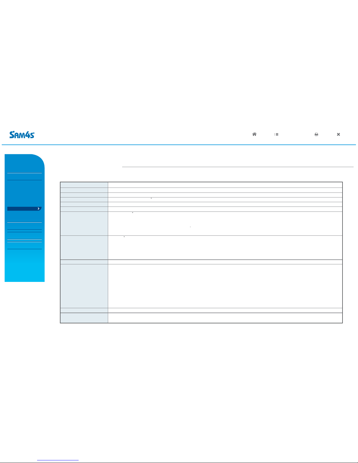
Read these cautions to avoid damage or injury.
Keep rated voltage.
The product can be damaged or burned by overvoltage.
Do not use damaged components.
The product may be damaged unless it is repaired at service center.
Install the product in a clean and dry place.
The product may not work properly in moist or dusty environments.
Always copy important files.
Always copy important files because data loss cannot be guaranteed by manufacturer.
Turn off the system and remove the power cable before the product is removed.
You may get an electric shock.
Do not use loose or damaged power cables.
There may be electric shock or fire.
Always connect power cable to a grounded 3-wire outlet.
It prevents electric shock from electrical short.
Install the product at an airy place.
The product may be transformed or burned by overheating if air vent is blocked.
Use multi consent which is only for computers.
There may be fire caused by overvoltage.
Use the cleaner which is only for computer.
Do not use benzene, thinner and alcohol or the procust may be damaged.
Keep the product away from heaters.
The product may be damaged, overheated or burned.
Turn on the system after turning on peripheral device. Turn off peripheral device after turn off the system.
The product may be damaged.
Install the product in a safe, stable place.
The product may be damaged or you may get injured if the product is dropped.
Keep the product away from magnetic materials.
The contents of HDD may be erased or the electronic components may be damaged.
Carefully store or dispose of plastic packing material .
It is dangerous if children put their head on it.
Do not touch the power plug with wet hands.
You may get an electric shock.
Do not touch modem, telephone line or exposed terminal during electrical storms.
There may be electric shock or fire.
Upgrade the system after shutting off the power of system and its peripheral device.
The product may be damaged.
Cautions!
!
HOME LIST HELP PRINT END
?
e-Manual
SPT-3700
System Introduction
Intro
Safety Notices Before
Installation or Use
Contents
System features
Specification(Options)
Name and
Function of Each Component
System Installation
System Utilization
System Expansion
Appendix A
BIOS Set up
Appendix B
System Configuration

PART 1. System Introduction
03. Contents
◀ 1 - 4 ▶
<Main body> <Quick manuals> <Magnetic DALLAS(option)> <Power Cable/Adaptor>
<Keyboard(option)>
<Mouse/Mouse pad(option)>
HOME LIST HELP PRINT END
?
e-Manual
SPT-3700
System Introduction
Intro
Safety Notices Before
Installation or Use
Contents
System features
Specification(Options)
Name and
Function of Each Component
System Installation
System Utilization
System Expansion
Appendix A
BIOS Set up
Appendix B
System Configuration

PART 1. System Introduction
04. System Features
◀ 1 - 5 ▶
System Introduction
System Features
This product has passed rigorous quality testing.
This product has a sophisticated design to arrange power and peripheral cables neatly and safely in any environment.
The all-in-one design incorporates the touch screen, credit card reader, smart card reader and various customer displays for clean and simple installations.
It is convenient to change Hard disk and memory.
It offers basic supports like OS restore, anti-virus vaccine.
15 TFT LCD Touch Screen
MSR(Magnetic Stripe Reader) (Option)
Wall Mount Bracket (Option)
All-in-One 15 or 7 or VFD Customer Display (Option)
Fingerprinter Reader (Option)
Cfast module (Option)
HOME LIST HELP PRINT END
?
e-Manual
SPT-3700
System Introduction
Intro
Safety Notices Before
Installation or Use
Contents
System features
Specification(Options)
Name and
Function of Each Component
System Installation
System Utilization
System Expansion
Appendix A
BIOS Set up
Appendix B
System Configuration

PART 1. System Introduction
05. System Specification(Options)
◀ 1 - 6 ▶
Processor
Chip sets
Graphic
Data storage device
Memory
BIOS
Display
Touch panel
OS
I/O Interface
Booting device
Power supply
Intel Atom Cedarview D2550 1.86GHZ Without FAN
Intel NM10
Intel Embedded Graphics
SATA-ll (3.0Gb/s) 2.5 HDD / SSD / Cfast
DDR lll SODIMM 2 Slot (Up to 4GB)
AMI (America Megatrends Inc.) UEFI BIOS
Size: 15 (38.1cm) 1024 * 768 resolution TFT LCD
Support Colors : 32 bit Color
Contrast Ratio : 450 : 1
Viewing Angle: Left-Right 150' / UP-DOWN 130
Backlight : 250 cd/㎡, 50,000hours of product life (CCFL type)
15 5-Wire Resistive Type
Interface : Serial COM5
Transparency : 80%
Surface Hardness : 3H
Hitting Life : 35 million times
Windows XP / 2000 / WEPOS / POSReady 2009 / POSReady 7
COM(Serial) port : D-SUB 9P x 3ports / RJ-45 x 2ports (COM6 is not allowable when using Option CDP)
5V or 12V or RI outputs through COM 1. 2. 3. 4 (BIOS setup)
PARALLEL port : D-SUB 25P x 1port
USB port : USB 2.0 side x 2Ports / back x 4Ports
Ethernet port : 10M / 100M / 1GB LAN RJ-45 x 1Port
Cash drawer port : RJ-11 x 1Port with options 12/24V
VGA Port : D-SUB 15P x 1
DC-OUTPUT port : 12 V DC-OUT 2.5 Φx 1Port
Audio port : Line-in x 1 / Line-out x 1 / Mike-in x 1Port
HDD, SSD, Cfast memory, external CD / DVD-ROM, USB memory etc.
AC INPUT : AC 100~240V / 50~60Hz, 1.5A
DC OUTPUT : 12V / 5.0A (60W)
General Specifications
HOME LIST HELP PRINT END
?
e-Manual
SPT-3700
System Introduction
Intro
Safety Notices Before
Installation or Use
Contents
System features
Specification(Options)
Name and
Function of Each Component
System Installation
System Utilization
System Expansion
Appendix A
BIOS Set up
Appendix B
System Configuration

PART 1. System Introduction
05. System Specification(Options)
◀ 1 - 7 ▶
Magnetic Swipe Reader(MSR)
Wall Mount
DALLAS Key
Customer display
Read Track: ISO track 1,2,3
Interface: Internal USB
Performance: 10~150CM/Sec
Head Reliability: 500,000 times
Error rate: Less than 0.5%
The device for attaching SPT-3700 on the wall
Magnet Type
VFD : 5 x 7 Dot 20 x 2 Character type
256 x 32 Graphic type
LCD : 7 (17.78cm) 800 x 480 16:9 type
15 (38.1cm) 1024 x 768 4:3 type
Optional Specifications
HOME LIST HELP PRINT END
?
e-Manual
SPT-3700
System Introduction
Intro
Safety Notices Before
Installation or Use
Contents
System features
Specification(Options)
Name and
Function of Each Component
System Installation
System Utilization
System Expansion
Appendix A
BIOS Set up
Appendix B
System Configuration

PART 1. System Introduction
06. Name and Function of Each Component
◀ 1 - 8 ▶
Front View
MSR(Magnetic Stripe Reader)
The device for recognizing credit cards
Magnetic cards recognition lamp
The light is on when recognizing credit cards.
Indicating lamp for LAN connection
The light is on when internet is connected.
Indicating lamp for HDD
The light is on when data in HDD is being used or read..
Indicating lamp for power supply
The light is on when the system is on.
Touch LCD
Stand
Dallas Key(Option)
Using for Dallas security
HOME LIST HELP PRINT END
?
e-Manual
SPT-3700
System Introduction
Intro
Safety Notices Before
Installation or Use
Contents
System features
Specification(Options)
Name and
Function of Each Component
System Installation
System Utilization
System Expansion
Appendix A
BIOS Set up
Appendix B
System Configuration

PART 1. System Introduction
06. Name and Function of Each Component
◀ 1 - 9 ▶
Side View
USB Connector
USB Devices can be used through this port, i.e.
USB scanner, USB Keyboard, USB Printer, etc.
SD CARD SLOT (Option)
SD Card, MMC Card can be used.
POWER BUTTON
Dummy for cable arrangement STAND
Turns On-Off your system.
ANGLE ADJUSTMENT LEVER
HOME LIST HELP PRINT END
?
e-Manual
SPT-3700
System Introduction
Intro
Safety Notices Before
Installation or Use
Contents
System features
Specification(Options)
Name and
Function of Each Component
System Installation
System Utilization
System Expansion
Appendix A
BIOS Set up
Appendix B
System Configuration

PART 1. System Introduction
06. Name and Function of Each Component
◀ 1 - 10 ▶
I / O
1. RJ-45 8pin COM(Serial) Port (CDP sharing COM6)
2. RJ-45 6pin Cash Drawer port
3. Setting switch of Cash drawer voltage. Select 12V or 24V(Factory status)
4. Cfast memory slot (option)
5. Audio port (Line-in / Line-out/ Mike-in)
6. USB 2.0 port
7. RJ-45 LAN (ETHERNET) port
8. D-SUB 9pin COM (Serial) port
9. D-SUB 25pin printer (LPT) port
10. D-SUB 15pin VGA port
11. 2.5Φ 12V DC Output (for Rear display)
12. DIN 4pin 12V DC Input (Input power connection)
1 2
35
6 8
9
6
1
10
8
11 12
7
4
HOME LIST HELP PRINT END
?
e-Manual
SPT-3700
System Introduction
Intro
Safety Notices Before
Installation or Use
Contents
System features
Specification(Options)
Name and
Function of Each Component
System Installation
System Utilization
System Expansion
Appendix A
BIOS Set up
Appendix B
System Configuration

PART 1. System Introduction
06. Name and Function of Each Component
◀ 1 - 11 ▶
Rear View
ANGLE ADJUSTMENT LEVER
Dummy for cable arrangement
Dual monitor expansion cover
7Inch Display or CDP(option)
CDP(all-in-one customer display) - option
It shows advertisements or calculation.
HOME LIST HELP PRINT END
?
e-Manual
SPT-3700
System Introduction
Intro
Safety Notices Before
Installation or Use
Contents
System features
Specification(Options)
Name and
Function of Each Component
System Installation
System Utilization
System Expansion
Appendix A
BIOS Set up
Appendix B
System Configuration

01. Remove The Cable Cover
◀ 2 - 1 ▶
Tilt its monitor back to see hooks fixing cable cover.
Push these hooks to remove the cover in order to see IO ports necessary for connecting peripherals.
Cover fixing hook
PART 2. System Installation
HOME LIST HELP PRINT END
?
e-Manual
SPT-3700
System Introduction
System Installation
Remove The Cable Cover
Remove Cable Tidy Dummy
Keyboard/Mouse Connection
Printer Connection
Serial Ports Connection
RJ-11 Cash Drawer Connection
RJ-45 LAN Cable Connection
USB Connection
DC Power Connection
System Utilization
System Expansion
Appendix A
BIOS Set up
Appendix B
System Configuration
1.
2.

◀ 2 - 2 ▶
* Remove the cable tidy dummy if necessary to route cables.
Remove dual monitor expansion cover for when a dual monitor is installed.
dual monitor expansion cover
Cable tidy dummy
02. Remove Cable Tidy Dummy
PART 2. System Installation
HOME LIST HELP PRINT END
?
e-Manual
SPT-3700
System Introduction
System Installation
Remove The Cable Cover
Remove Cable Tidy Dummy
Keyboard/Mouse Connection
Printer Connection
Serial Ports Connection
RJ-11 Cash Drawer Connection
RJ-45 LAN Cable Connection
USB Connection
DC Power Connection
System Utilization
System Expansion
Appendix A
BIOS Set up
Appendix B
System Configuration

◀ 2 - 3 ▶
Connect USB type keyboard & mouse.
This system supports parallel, serial & USB interface printers.
Connect the cable suitable to interface.
<Mouse>
<COM port
connection>
<Key board>
<parallel port
connection>
<USB Connection>
03. Connecting Keyboard & Mouse
04. Connecting Printer
PART 2. System Installation
HOME LIST HELP PRINT END
?
e-Manual
SPT-3700
System Introduction
System Installation
Remove The Cable Cover
Remove Cable Tidy Dummy
Keyboard/Mouse Connection
Printer Connection
Serial Ports Connection
RJ-11 Cash Drawer Connection
RJ-45 LAN Cable Connection
USB Connection
DC Power Connection
System Utilization
System Expansion
Appendix A
BIOS Set up
Appendix B
System Configuration

◀ 2 - 4 ▶
Connect a barcode scanner and serial interface device to the serial port.
Each serial device a different specification of power supply.
COM voltage can be set RI/5V/12V.
Voltage setup can be done in BOIS, referring to Appendix A (BIOS set up).
Use RJ-11 drawer port in system when Cash Drawer is needed.
(Use SAM4S Cash Drawer).
Cash drawer has 12V/24V that you can choose by the switch.
Refer to the setup method and name and function of each component on page B-7.
You must check the used voltage of the cash drawer before connection.
Cash drawer may not work or could be damaged if you connect it with different setup.
Note!
<Barcode Scanner>
<Cash Drawer>
05. Connecting Serial Port Device Such as a Barcode Scanner
06. Connecting RJ-11 Cash Drawer
PART 2. System Installation
HOME LIST HELP PRINT END
?
e-Manual
SPT-3700
System Introduction
System Installation
Remove The Cable Cover
Remove Cable Tidy Dummy
Keyboard/Mouse Connection
Printer Connection
Serial Ports Connection
RJ-11 Cash Drawer Connection
RJ-45 LAN Cable Connection
USB Connection
DC Power Connection
System Utilization
System Expansion
Appendix A
BIOS Set up
Appendix B
System Configuration

◀ 2 - 5 ▶
Connect LAN cable to RJ-45 LAN port to use internet.
It supports 100Mbps/1Gbps.
USB connectors are located on the side of the LCD panel and the connection
panel located under the display. You can connect various USB devices such
as keyboard, mouse, CCD camera, printer, etc.
(Separate device drivers may be required.)
<LAN Herb>
<Mouse> <Key Board>
<CCD Camera>
<USB Memory>
PART 2. System Installation
07. Connecting RJ-45 LAN Cable
08. Connecting USB device
HOME LIST HELP PRINT END
?
e-Manual
SPT-3700
System Introduction
System Installation
Remove The Cable Cover
Remove Cable Tidy Dummy
Keyboard/Mouse Connection
Printer Connection
Serial Ports Connection
RJ-11 Cash Drawer Connection
RJ-45 LAN Cable Connection
USB Connection
DC Power Connection
System Utilization
System Expansion
Appendix A
BIOS Set up
Appendix B
System Configuration

09. Connecting DC Power Supply Cable
◀ 2 - 6 ▶
Connecting DC power supply cable to the bottom of system.
(Free Voltage system adapter is used. Both 100V and 220V can be used.)
▶ Adapter for this system should be only from SAM4S .
▶ SAM4S cannot be responsible for the damage caused by
using other products except SAM4S.
Cautions!
!
PART 2. System Installation
HOME LIST HELP PRINT END
?
e-Manual
SPT-3700
System Introduction
System Installation
Remove The Cable Cover
Remove Cable Tidy Dummy
Keyboard/Mouse Connection
Printer Connection
Serial Ports Connection
RJ-11 Cash Drawer Connection
RJ-45 LAN Cable Connection
USB Connection
DC Power Connection
System Utilization
System Expansion
Appendix A
BIOS Set up
Appendix B
System Configuration
Table of contents