Pag. 10/14
axial piston
R
axial pistonaxial piston
R
Flussaggio del circuito chiuso
Dopo aver completato la procedura di primo avviamento
occorre procedere al flussaggio del circuito chiuso: negli
impianti nuovi, dopo ogni manutenzione di pompa o mo-
tore o quando una delle due linee di pressione fra pom-
pa e motore sia stata sostituita e/o scollegata. Questa
precauzione è fondamentale per rimuovere i contami-
nanti introdotti durante il montaggio e quelli presenti in
tubi e raccordi. Sia la pompa che il motore funzioneran-
no anche senza procedere al flussaggio del circuito
chiuso, ma la loro durata potrebbe esserne seriamente
compromessa.
Per poter effettuare il flussaggio è necessario un filtro in
linea con pressione di funzionamento nominale e porta-
ta adeguate alle caratteristiche della pompa. Il setto fil-
trante deve essere almeno da 10µm assoluti - racco-
mandati 4µm assoluti.
Dal momento che il filtro ha una direzione di flusso ob-
bligata, nell’eseguire il flussaggio il regolatore della
pompa dovrà essere azionato in modo da ottenere la
direzione di mandata richiesta (nel dubbio, il ramo A o B
a pressione più alta è il ramo di mandata!).
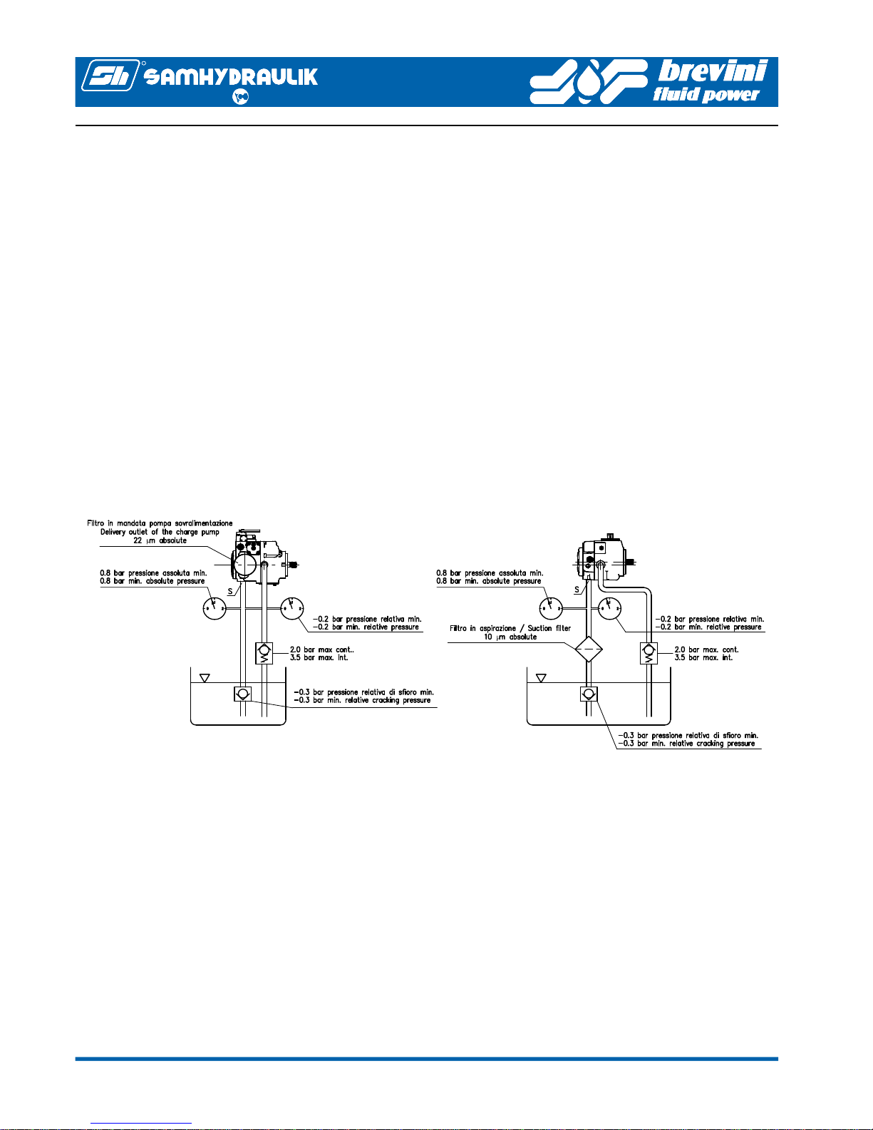
Due possibili montaggi del filtro in linea sono possibili
(vedi figura 5).
A Collegando il filtro al posto del motore.
B Collegando il filtro sul ramo di ritorno alla pompa pri-
ma che esso ritorni alla pompa e escludendo il moto-
re per mezzo di un collegamento temporaneo
(soluzione preferibile).
Il flussaggio è da considerarsi soddisfacente quando il
livello di contaminazione dell’olio nel circuito chiuso se-
condo la norma ISO 4406 è almeno pari a 18/16/13 o
inferiore.
Lo stesso livello massimo di contaminazione accettabi-
le, 18/16/13, si applica a tutto l’impianto.
ATTENZIONE: nel caso in cui vi siano nel circuito più
motori in parallelo, è necessario fare in modo di flussare
correttamente ciascun “ramo” del circuito, ovvero i con-
dotti che collegano ciascun motore al punto in cui il flus-
so viene diviso. Per fare ciò, raccomandiamo di inserire
in serie al tubo di corto circuito di ciascun motore (come
da montaggio B - vedi sopra) una valvola di esclusione
a sfera per alta pressione. Il corrispondente ramo di cir-
cuito verrà flussato con la valvola aperta, mentre le altre
sono chiuse. Ripetendo la medesima operazione per
ogni ramo si riesce a flussare completamente il circuito.
Una volta completato il flussaggio, il filtro e gli eventuali
tubi ausiliari impiegati devono essere rimossi e l’impian-
to ripristinato nella configurazione di funzionamento nor-
male.
A questo punto è possibile procedere con il collaudo
sotto carico della macchina ed all’effettuazione delle
eventuali tarature.
Closed loop flushing procedure
After the first starting is completed, the closed loop
flushing must be done. This procedure applies to brand
new machines, after a major maintenance work or when
the pressure lines between pump and motor have been
changed or disconnected. This procedure is mandatory
to remove any presence of contaminant in hoses, pipes
and fittings. Both pump and motor will function even if
the flushing procedure is not performed, but the service
life of both could be seriously reduced.
To flush the closed loop it must be used an in line filter
with suitable pressure and flow rate rating. The filter
element must be preferably 4µm absolute - 10µm
absolute can be used as an alternative.
Since the filter has only one possible flow direction, the
pump control must be operated to achieve the correct
flow direction (if one it’s not sure of it, check the highest
pressure side between A or B: this will be the output
flow side!).
The in line filter can be mounted in two different position
on option (see figure 5):
A Connecting the pressure lines of the motor to the
filter.
B Connecting the filter on the return line before the oil
goes back to the pump and by passing the motor by
the means of an additional hose (preferable
solution).
The flushing can be stopped as the oil contamination
level in the closed loop according to ISO 4406 is at least
18/16/13 or lower.
The same maximum 18/16/13 acceptable oil
contamination level applies to the whole circuit.
WARNING: When two or more motors are connected in
parallel layout to the pump, it is necessary to ensure the
correct flushing of each of the circuit sections
connecting the motors. To do so, it is advisable to
bypass each of the motors connecting a ball type high
pressure valve (two way-two positions, manually
operated) to the by pass line (as per position B - see
above). By opening one of said valves while the others
are closed and starting the above mentioned flushing
procedure it is possible to ensure the correct flushing of
the correspondent circuit section. The procedure must
be repeated for each of the circuit sections.
When the flushing is completed, the in line filter and the
eventual auxiliary hoses must be removed to configure
the circuit to the design layout.
After the circuit has been restored to the design layout,
the machine can be tested under load, and the eventual
pressure adjustments and final tests can be done.