GHIBLI 10:1 HYDRO CLEANER
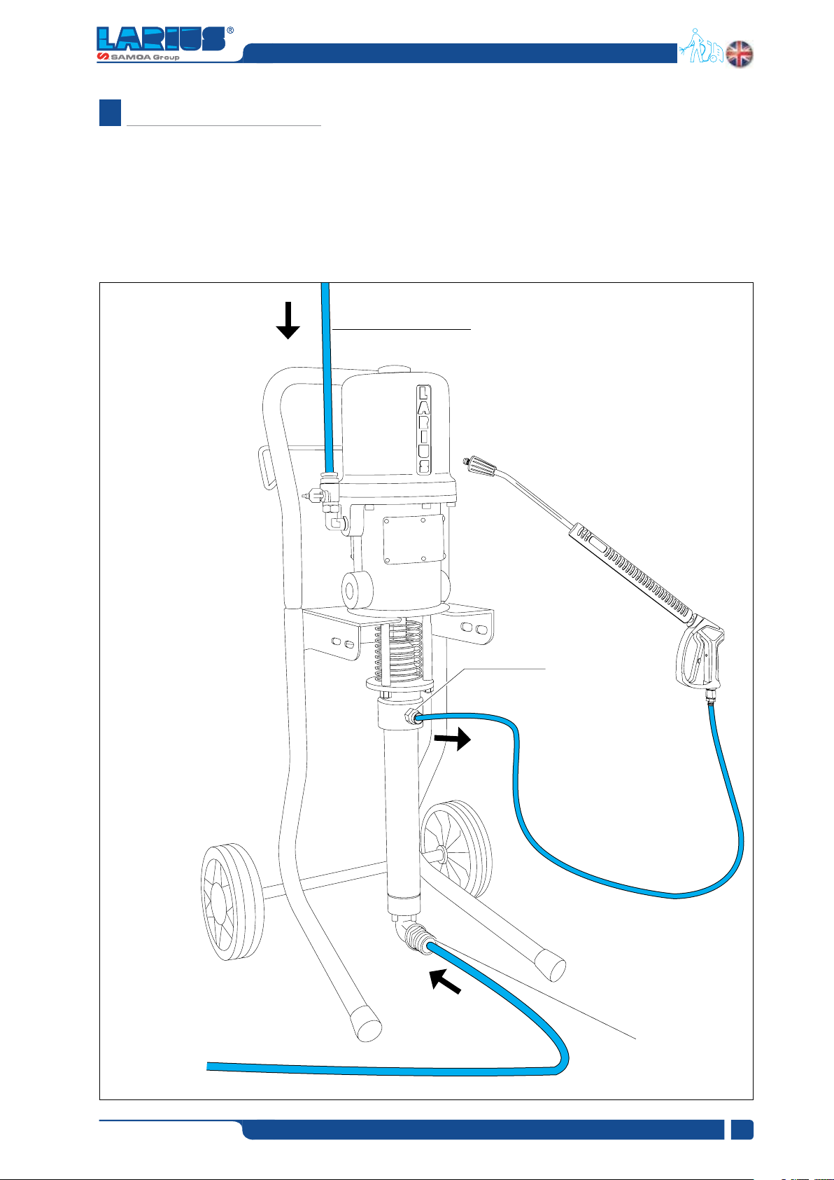
TRANSPORT AND
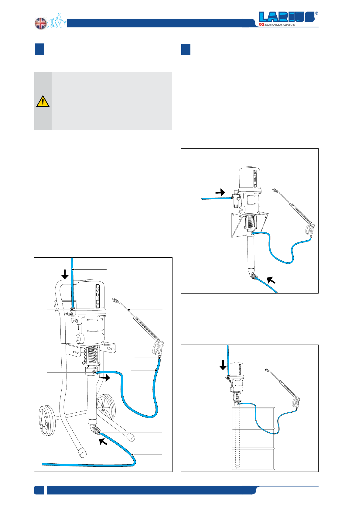
UNPACKING
EG
F
www.larius.com
6
REV. 01 - 12/2020 - Cod. 150186
and markings on the outside of the packing.
used is large enough for such purposes, is properly lit and has
a clean, smooth oor surface.
handling and should use the maximum care so as not to damage
the individual parts or injure anyone.
To perform the unloading operation, use only qualied and
trained personnel (truck and crane operators, etc.) and also
suitable hoisting equipment for the weight of the installation
or its parts.
Follow carefully all the safety rules.
The personnel must be equipped with the necessary safety
clothing.
operations and transport to the workplace of the machine.
Unpack the machine and verify if there has been any damage
due to transportation.
In case of damage, call immediately LARIUS and the Shipping
Agent. All the notices about possible damage or anomalies must
arrive timely within 8 days at least from the date of receipt of
the plant through Registered Letter to the Shipping Agent and
to LARIUS.
The conditions of guarantee do not apply in the
following situations:
- improper washing and cleaning of components
causing malfunction, wear or damage to the
equipment or any of its parts;
- improper use of the equipment;
- use that does not conform with applicable
national legislation;
- incorrect or faulty installation;
-modifications,interventionsandmaintenancethat
have not been authorised by the manufacturer;
- use of non-original spare parts or parts that do
not correspond to the specific model;
- total or partial non-compliance with the
instructions provided.
CONDITIONS OF GUARANTEE
The disposal of packaging materials is a customer’s
competence and must be performed in accordance
with the regulations in force in the country where
the plant is installed and used.It is nevertheless
sound practice to recycle packaging materials in an
environment-friendly manner as much as possible.
THOSE RISKS STEMMING FROM ACCIDENTS, ABOUT THE
USE OF SAFETY DEVICES FOR THEIR OWN SAFETY AND
ABOUT THE GENERAL RULES FOR ACCIDENT PREVENTION
IN COMPLIANCE WITH INTERNATIONAL REGULATIONS AND
WITH THE LAWS OF THE COUNTRY WHERE THE PLANT IS
USED.
COMPLY WITH THE ACCIDENT PREVENTION AND ALSO
ENVIRONMENTAL REGULATIONS IN FORCE IN THE COUNTRY
WHERE THE PLANT IS INSTALLED AND USED.
WHERE YOU ARE WORKING CREATES A POTENTIAL RISK
OF ACCIDENTS.
STANCE.
DAMAGED PARTS AND THE MACHINE CAN WORK PROPERLY.
THE REGULATIONS IN FORCE.
EQUIPMENT OUT OF THE WORK AREA.
NEVER EXCEED THE MAXIMUM WORKING PRESSURE
INDICATED.
(IF PROVIDED) NEVER POINT THE SPRAY GUN AT
YOURSELVES OR AT OTHER PEOPLE. THE CONTACT WITH
THE CASTING CAN CAUSE SERIOUS INJURIES. NEVER
UNDERVALUE A WOUND CAUSED BY THE INJECTION OF
A FLUID.
PERFORMING ANY CHECK OR PART REPLACEMENT OF
THE EQUIPMENT.
REGULARLY THE COMPONENTS OF THE SYSTEM.
REPLACE THE PARTS DAMAGED OR WORN.
(IF PROVIDED) TIGHTEN AND CHECK ALL THE FITTINGS
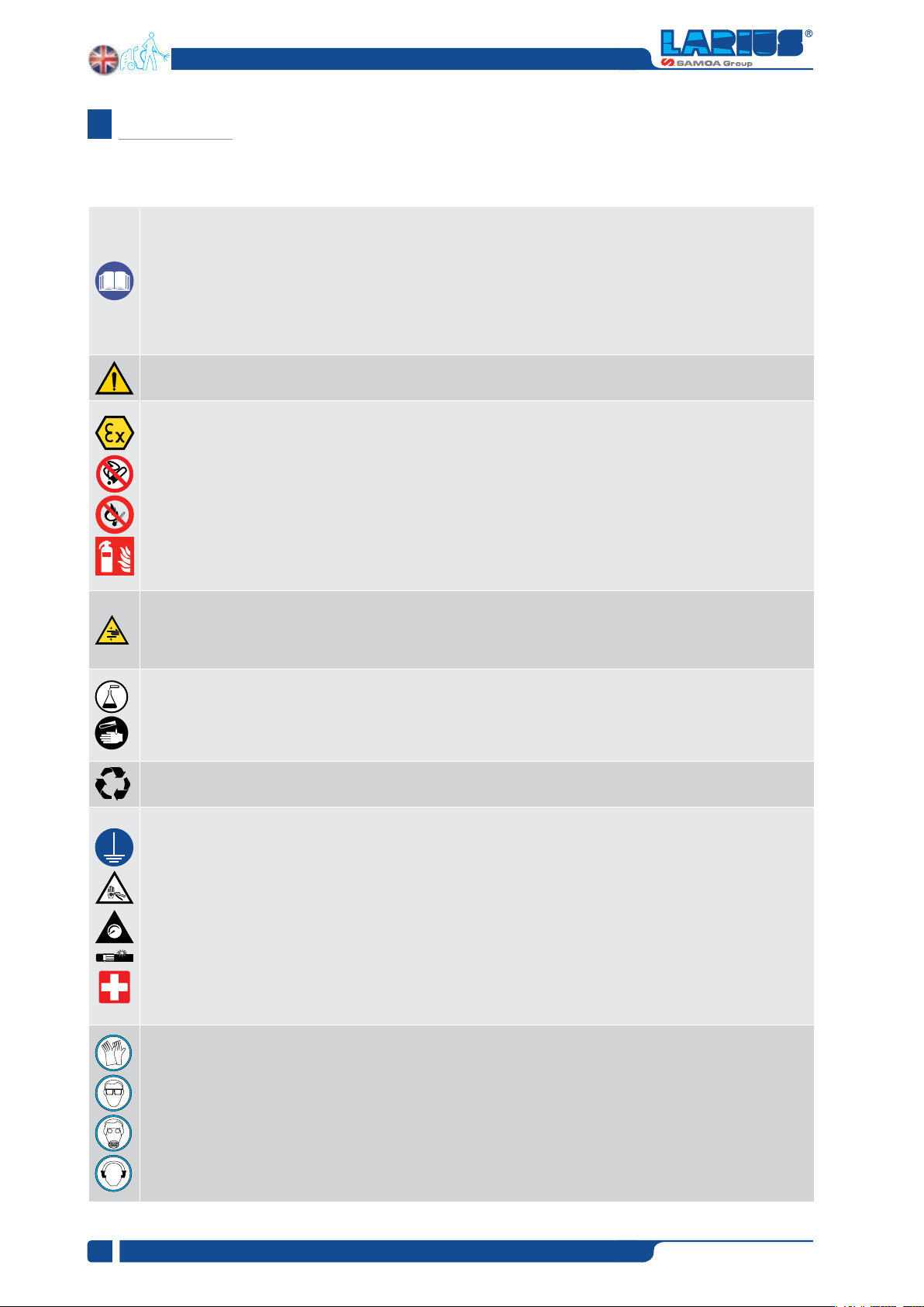
SAFETY RULES
Readcarefullyandentirelythefollowinginstructions
before using the product. Please save these
instructions in a safe place.
The unauthorised tampering/replacement of one
or more parts composing the machine, the use of
accessories, tools,expendable materialsother than
those recommended by the manufacturer can be a
danger of accident.
The manufacturer will be relieved from tort and
criminal liability.