Samson Trovis 5475-2 Service manual

Automation System TROVIS 5400
Heating and District Heating Controller
TROVIS 5475-
Edition January 001
Firmware Version 1.10
Mounting and operating instructions
EB 5475- EN
Fig. 1 ⋅ TROVIS 5475-2
®
Electronics from SAMSON

Contents . . . . . . . . . . . . . . . . . . . . . . . . . . . . . . . . . . . . . Page
1. General . . . . . . . . . . . . . . . . . . . . . . . . . . . . . . . . . . . . 4
1.1 Notes for the user . . . . . . . . . . . . . . . . . . . . . . . . . . . . . . . . 4
1.2 Te hni al data . . . . . . . . . . . . . . . . . . . . . . . . . . . . . . . . . 5
1.3 Sensor resistan e values . . . . . . . . . . . . . . . . . . . . . . . . . . . . 6
. Installation . . . . . . . . . . . . . . . . . . . . . . . . . . . . . . . . . . 7
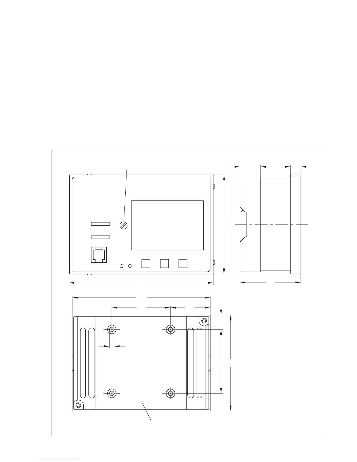
2.1 Installing the ontroller . . . . . . . . . . . . . . . . . . . . . . . . . . . . . 7
2.2 Installing the sensors . . . . . . . . . . . . . . . . . . . . . . . . . . . . . . 8
3. Electrical connections . . . . . . . . . . . . . . . . . . . . . . . . . . . . . 8
3.1 General . . . . . . . . . . . . . . . . . . . . . . . . . . . . . . . . . . . . 8
3.2 Conne ting the ontroller . . . . . . . . . . . . . . . . . . . . . . . . . . . . 9
3.3 Conne ting the sensors . . . . . . . . . . . . . . . . . . . . . . . . . . . . . 9
3.4 Terminal wiring diagrams . . . . . . . . . . . . . . . . . . . . . . . . . . . . 9
4. Description of the controller functions . . . . . . . . . . . . . . . . . . . . . . 13
4.1 Optimize . . . . . . . . . . . . . . . . . . . . . . . . . . . . . . . . . . . 13
4.2 Adaptation . . . . . . . . . . . . . . . . . . . . . . . . . . . . . . . . . . 13
4.3 Redu ed operation . . . . . . . . . . . . . . . . . . . . . . . . . . . . . . . 14
4.4 Summer time operation . . . . . . . . . . . . . . . . . . . . . . . . . . . . . 14
4.5 Automati lo k reset summer time/winter time . . . . . . . . . . . . . . . . . . 15
4.6 Publi holidays and va ations . . . . . . . . . . . . . . . . . . . . . . . . . . 15
4.7 Delayed outdoor temperature adaptation . . . . . . . . . . . . . . . . . . . . 15
4.8 Limitation of the return flow temperature . . . . . . . . . . . . . . . . . . . . . 16
4.9 Limitation of the system deviation for OPEN signal . . . . . . . . . . . . . . . . 17
4.10 For ed harging of the drinking water storage tank . . . . . . . . . . . . . . . . 17
4.11 Thermal disinfe tion of the drinking water storage tank . . . . . . . . . . . . . . 17
4.12 Frost prote tion . . . . . . . . . . . . . . . . . . . . . . . . . . . . . . . . . 17
4.13 Defe tive sensors . . . . . . . . . . . . . . . . . . . . . . . . . . . . . . . . 18
4.14 For ed operation of the pumps . . . . . . . . . . . . . . . . . . . . . . . . . 18
4.15 Limitation of flow rate or apa ity . . . . . . . . . . . . . . . . . . . . . . . . 19
5. System descriptions and diagrams . . . . . . . . . . . . . . . . . . . . . . . 20
5.1 System ode number 1.0 . . . . . . . . . . . . . . . . . . . . . . . . . . . . 20
5.2 System ode number 2.0 . . . . . . . . . . . . . . . . . . . . . . . . . . . . 21
System ode number 2 .0 with hangeover valve . . . . . . . . . . . . . . . . . 21
System ode number 2.1 . . . . . . . . . . . . . . . . . . . . . . . . . . . . 23
5.3 System ode number 3.0 . . . . . . . . . . . . . . . . . . . . . . . . . . . . 24
5.4 System ode number 4.0 . . . . . . . . . . . . . . . . . . . . . . . . . . . . 26
System ode number 4 .1 . . . . . . . . . . . . . . . . . . . . . . . . . . . . 27
System ode number 4.2 . . . . . . . . . . . . . . . . . . . . . . . . . . . . 28
5.5 System ode number 5.0 . . . . . . . . . . . . . . . . . . . . . . . . . . . . 29
5.6 System ode number 6.0 . . . . . . . . . . . . . . . . . . . . . . . . . . . . 30
2

6. Operation . . . . . . . . . . . . . . . . . . . . . . . . . . . . . . . . . . 32
6.1 Operating ontrols . . . . . . . . . . . . . . . . . . . . . . . . . . . . . . 32
6.2 Sele ting the operating modes . . . . . . . . . . . . . . . . . . . . . . . . . 32
6.2.1 Remote ontrolling the heating system . . . . . . . . . . . . . . . . . . . . . 33
6.3 Control levels . . . . . . . . . . . . . . . . . . . . . . . . . . . . . . . . . 34
6.3.1 Configuration level . . . . . . . . . . . . . . . . . . . . . . . . . . . . . . 34
6.3.2 Parameter level . . . . . . . . . . . . . . . . . . . . . . . . . . . . . . . . 34
6.3.3 Operating level . . . . . . . . . . . . . . . . . . . . . . . . . . . . . . . . 34
Increasing/decreasing the room temperature . . . . . . . . . . . . . . . . . 37
7. Starting up and configuring the controller . . . . . . . . . . . . . . . . . . . 38
7.1 Configuration . . . . . . . . . . . . . . . . . . . . . . . . . . . . . . . . 38
7.1.1 Setting the ode number . . . . . . . . . . . . . . . . . . . . . . . . . . . 38
7.1.2 Setting the system ode number (Anl) . . . . . . . . . . . . . . . . . . . . . 39
7.1.3 Setting the fun tion blo ks . . . . . . . . . . . . . . . . . . . . . . . . . . . 39
7.1.4 Fun tion blo k list . . . . . . . . . . . . . . . . . . . . . . . . . . . . . . . 42
7.1.4 Sensor alibration . . . . . . . . . . . . . . . . . . . . . . . . . . . . . . 46
7.2 Parameterization . . . . . . . . . . . . . . . . . . . . . . . . . . . . . . . 47
7.2.1 Resetting to default values . . . . . . . . . . . . . . . . . . . . . . . . . . . 47
7.2.2 Entering and modifying user data . . . . . . . . . . . . . . . . . . . . . . . 48
Entering urrent time and date . . . . . . . . . . . . . . . . . . . . . . . . . 48
Entering parameters for heating circuit:
Heating hara teristi s and temperatures . . . . . . . . . . . . . . . . . . . 48
Time s hedule for heating . . . . . . . . . . . . . . . . . . . . . . . . . . . 51
Publi holidays . . . . . . . . . . . . . . . . . . . . . . . . . . . . . . . . 53
Va ations . . . . . . . . . . . . . . . . . . . . . . . . . . . . . . . . . . 53
Entering parameters for drinking water circuit:
Temperatures . . . . . . . . . . . . . . . . . . . . . . . . . . . . . . . . . 54
Time s hedule for drinking water heating . . . . . . . . . . . . . . . . . . . . 56
Time s hedule for ir ulation pump . . . . . . . . . . . . . . . . . . . . . . 56
7.3 Personal ode numbers, lo king the mode swit h for manual operation and
enabling the write prote t fun tion for the onfiguration level . . . . . . . . . . 57
7.4 Configuring the orre tion swit h . . . . . . . . . . . . . . . . . . . . . . . 58
8. Data transfer using memory module . . . . . . . . . . . . . . . . . . . . . 59
9. Configured data . . . . . . . . . . . . . . . . . . . . . . . . . . . . . . . 60
Assembly, start-up and operation of the devi e may only be performed
by trained and experien ed personnel familiar with this produ t. Proper
shipping and appropriate storage are assumed.
The ontroller is designed for use in power installations. For onne tion
and maintenan e you are required to observe the relevant safety regula-
tions.
!
3

1. General
The heating and distri t heating ontroller is designed for weather- ompensated flow tempera-
ture ontrol. This means it ontrols the flow temperature of a heating system based on a heating
hara teristi so that the room temperature is always maintained at the desired level regardless
of the outdoor temperature. When used as a distri t heating ontroller, the ontroller an limit
the return flow temperature variably a ording to the outdoor temperature.
A drinking water heating system may be operated from the primary heating ir uit, using a se -
ond ontrol loop, or from the se ondary heating ir uit.
A differential temperature ontrol featuring a meter tra king the operating hours of the solar
ir uit pump is in luded in three system onfigurations for the solar heating of drinking water
storage tanks.
The onne ted sensors allow the ontroller to measure the respe tive temperatures whi h are
transmitted to the entral signal pro essing system. Subsequently, this system issues a three-step
or on/off ontrol signal orresponding to the preset set points for ea h of the two ontrol loops.
In addition, the ontroller ontrols the heating ir ulation pump and the pumps for drinking
water heating. The signal from a heat meter that is proportional to the flow rate or apa ity an
be onne ted to a pulse or urrent input. This enables the limitation of a maximum and/or mini-
mum flow rate or apa ity.
These mounting and operating instructions are valid for:
Firmware version 1.0 upwards
(The firmware version installed appears for 2 se onds in the display when the ontroller is
swit hed on)
Whats new compared to the previous version?
The ir ulation pump ZP runs on a time s hedule in all systems.
1.1 Notes for the user
The installation of the ontroller and its ele tri al onne tion des ribed in the following and,
must be arried out by authorized personnel only.
The settings for onfigurations des ribed in hapter 7.1 also require spe ialized knowledge of
heating systems and should only be performed by an expert. This also applies for the des rip-
tion of the ontroller fun tions and system onfigurations des ribed in hapter 4 and 5.
The start-up of the ontroller is normally arried out by authorized personnel all onfiguration
data should be entered into the onfigured data tables in hapter 9.
The ontroller is programmed with default temperature values and time s hedules that an be
hanged on start-up or by the user at a later date over the menu des ribed in hapter 7.2.2.
The settings for the end user and non-expert should be restri ted to hanging the heatings flow
temperature to in rease or de rease room temperatures ( hapter 6.3.3 on page 37) and
hanging the set times-of-use ( hapter 7.2.2 on page 51).
The current time and date are saved in memory for at least 4 hours when the controller is
left unconnected to the power supply. Other configuration data are stored in memory indefi-
nitely and cannot be lost.
4

1.1 Technical data
Inputs
Sensor inputs Max. 7 PTC and Pt 100 or NTC and Pt 100, or Pt 1000 and Pt
100 sensors
2-wire ir uit
(heating ir uit/drinking water ir uit)
2 flow temperature sensors, alternatively 1 solar olle tor sensor
1 room temperature sensor
1 outdoor temperature sensor1)
1 return flow temperature sensor ( 2 in system ode no. 4)
2 storage tank temperature sensors
Binary inputs Storage tank thermostat
Additional inputs Current input 4(0)...20 mA for flow rate limitation or pulse
ounting input for limitation of apa ity or flow rate
Current input 4(0)...20 mA for outdoor temperature
Remote ontrol option for orre ting flow temperature and
sele ting the operating mode
Outputs
Control signal y Three-step signals: max. load 250 V AC, 2 A;
min. 10 mA, varistor suppression 300 V
On/off signal: max. load 250 V AC, 2 A;
min. 10 mA, varistor suppression 300 V
Binary outputs Max. 4 outputs for pump ontrol
Load: max. 250 V AC, 2 A min. 10 mA, varistor
suppression 300 V
Control parameters Kp = 0.1...50; Tn = 1...999 s; valve transit time Ty = 15...240 s
Operating voltage 230 V AC (+10 %/15 %), 48 to 62 Hz,
Power failure: All parameter and onfiguration data are saved
in an EEPROM.
Power onsumption Approx. 1.5 VA
Temperature range Operation: 0...40 Storage: 20 to 60 °C1)
Degree and lass of prote tion IP 40 a ording to IEC 529 and II a ording to VDE 0106
Degree of ontamination 2 a ording to VDE 0110
Overvoltage ategory II a ording to VDE 0110
Humidity rating F a ording to VDE 40040
Noise immunity Corresponding to EN 50082 Part 1
Noise emission Corresponding to EN 50081 Part 1
Weight approx. 0.5 kg
1) On using Pt100 or Pt100 resistan e thermometers, permissible temperature
range down to −65 °C, however, display only indi ates down to −40 °C
5

CAUTION
Safety features su h as frost prote tion monitoring and ex ess temperature prote tion are not
a tive in the following ases:
•Defe tive heating ontroller and failure of its fun tions
•Sensors are faulty, not onne ted or have not been dea tivated
•No power supply to the ontroller
•Mode swit h set to manual operation
1. Sensor resistance values
Resistance thermometer with PTC measuring element
Sensors for outdoor temperature Type 5224, for flow and return flow temperature Types 5264
and 5265, for storage tank temperature Type 5264, sensor for room temperature with remote
ontrol Type 5244
°C 20 10 0 +10 +20 +25 +30 +40 +50 +60 +70 +80 +90 +100 +110 +120
Ohm 694 757 825 896 971 1010 1050 1132 1219 1309 1402 1500 1601 1706 1815 1925
Room temperature
sensor with remote
ontrol Type 5244
Swit h position " lo k", terminals 1 and 2 °C +10 +15 +20 +25 +30
Ohm 679 699 720 741 762
Resistance thermometer with Pt 100 measuring element
Sensors for outdoor temperature Type 5225, for flow and return flow temperature Types 5204
and 5205-47, for storage tank temperature Types 5205-46 and 5205-48, sensor for room tem-
perature Type 5255
°C -35 -30 - 5 - 0 -15 -10 -5 0 5 10
Ohm 86.25 88.22 90.19 92.16 94.12 96.09 98.04 100.00 101.95 103.90
°C15 0 530354045505560
Ohm 105.85 107.79 109.73 111.67 113.61 115.54 117.47 119.40 121.32 123.24
°C 65 70 75 80 85 90 95 100 105 110
Ohm 125.16 127.07 128.98 130.89 132.80 134.70 136.60 138.50 140.39 142.29
°C 115 1 0 1 5 130 135 140 145 150
Ohm 144.17 146.06 147.94 149.82 151.70 153.58 155.45 157.31
Resistance values with Pt1000 measuring element
Use the resistan e values in the table for the Pt100 and multiply the values by the fa tor of 10.
Sensor for outdoor temperature Type 5227, for flow and return flow temperature Types 5207-
21, 5207-27, 5277 (thermowells required) and Type 5267 (surfa e sensor),
for storage tank temperature Type 5207-46 and Type 5207-48,
sensor for room temperature Type 5257-1,
room temperature sensor with remote ontrol Type 5257-4.
6

. Installation
.1 Installing the controller
The ontroller is made up of the ontroller asing whi h ontains the ele troni s omponents
and the rear asing se tion with the terminal blo ks. To onne t the ontroller, remove the s rews
on the front panel and separate the ontroller housing from the rear asing.
For wall mounting, use four s rews to mount the rear asing to a wall. The distan es between the
holes are shown in Fig. 2.
For top hat rail mounting, mount the ontroller onto the top hat rail using the spring-mounted
hook on the rear asing.
For panel mounting, push the ontroller asing through the panel ut-out (92 x 138 mm) and in-
sert the fastening lips (delivered with the ontroller) into the not hes at the top and bottom of
the asing. Then turn the threaded bolts in the dire tion of the ontrol panel so that the asing is
pressed with its front frame against the ontrol panel.
144 59
30 10
138
57 41
Ø 4.5
98
62
15
93
Fixing s rew on ontroller se tion
Fastening se tion on ontroller rear asing
Panel ut-out
92 x 138 mm
Fig. 2 ⋅ Dimensional diagram
7

. Installing the sensors
. .1 Outdoor sensor
Use two s rews to mount the outdoor sensor to the outside wall at an appropriate pla e. Make
sure that the sensor is mounted away from dire t heat sour es (windows, vents et .). In ase of
single family dwellings, preferably mount the sensor on the wall at the side of the house where
the most frequently o upied rooms are situated.
. . Flow/return flow sensor
Mount the sensor as du t sensor or surfa e sensor in an easily a essible lo ation near the on-
trol valve:
Duct sensor: Insert the du t sensor into a thermowell as far as it will go.
Surface sensor: Remove insulation from the flow pipe where the sensor is to be mounted and
polish the pipe lean. Firmly press the sensor onto the pipe and se ure it to the pipe using the en-
losed tightening strap.
. .3 Room sensor
Mount the sensor on the wall approx. 150 m above the floor at an appropriate pla e. Make
sure that the air ir ulation is not obstru ted by upboards, urtains or similar items.
3. Electrical connections
3.1 General
CAUTION!
For wiring and connection of the controller, you are required to observe the VDE
regulations and the regulations of the local power supply company. For this reason,
this type of work must be carried out by a specialist.
•Use separate ables for 230 V supply line and the signal lines!
•Also use separate ables for the digital signal lines (bus lines) and the analog signal lines
(sensor lines).
•In systems with a high ele tromagneti noise level, we re ommend that shielded ables be
used for the analog signal lines.
Ground the shield at the inlet or outlet of the ontrol abinet, using the largest possible ross
se tion and via the shortest possible route.
The entral grounding point must be onne ted to the grounding ondu tor using a min.
10 mm2 able.
As a rule, the shield needs only be grounded on one side at the ontrol abinet inlet, ex ept
when an equipotential bonding exists that has mu h lower resistan e than the shield resist-
an e.
•To in rease the noise immunity, make sure that there is a minimum distan e of 10 m be-
tween the power ables and signal lines. We re ommend that this distan e between these
lines is also kept in the ontrol abinet!
•Indu tan es in the ontrol abinet, e.g. onta tor oils, must be equipped with suitable inter-
feren e suppressors (RC elements)!
Control abinet elements with a high field strength, e.g. transformers or frequen y onver-
ters, should be shielded by means of separators that have good hassis ground.
!
8

Surge protection
The following measures must be taken if lines are installed outside of the building or over long
distan es:
•The shield of signal lines routed outside of buildings must have urrent arrying apa ity
and must be grounded on both sides.
•Surge diverters must be installed at the ontrol abinet inlet.
3. Connecting the controller
Conne t the ontroller on the basis of the relevant terminal diagrams of the asso iated system
ode numbers (Fig. 3 to 10).
The power supply se tion of the ontroller terminals 14 to 26 must be onne ted using wires
with a ross-se tion of 1.5 mm2 at the minimum.
Kno k out the holes marked on the rear asing for the able entries and insert the en losed self-
sealed grommets or suitable glands.
3.3 Connecting the sensors
Conne t the ables with a ross-se tion of min. 0.5 mm2 to the terminal strip terminals 1
to 13 on the rear asing. See hapter 7.1.4 for Pt100 (Pt1000/PTC) on sensor alibration.
3.4 Terminal wiring diagrams
Legend for ir uit diagrams:
AF Outdoor sensor SLP Storage tank harging pump
RF Room sensor UP Cir ulation pump of heating ir uit
RÜF Return flow sensor ZP Cir ulation pump of drinking water ir uit
SF Storage tank sensor WMZ Heat meter
VF Flow sensor Solar ir uit:
TW Drinking water ir uit CF Solar ir uit olle tor sensor
HK Heating ir uit CP Solar ir uit pump
2 PKT On/off
With 0 …20 mA
50 Ω onne t in parallel
Fig. 3
System ode no. 1 Option Type 5244
Type 5257-4
9

Fig. 6
System ode no. 3.0
Fig. 4
System ode no. 2.0
Fig. 5
System ode no. 2.1
Option Type 5244
Type 5257-4
Stage1
Stage 2
With 0 …20 mA
50 Ω onne t in parallel
Thermostat
Option Type 5244
Type 5257-4
With 0 …20 mA
50 Ω onne t in parallel
Thermostat
Changeover
valve
Option Type 5244
Type 5257-4
With 0 …20 mA
50 Ω onne t in parallel
10

With 0 …20 mA
50 Ω onne t in parallel
Fig. 7
System ode no. 4.0
Fig. 9
System ode no. 5.0
Fig. 8
System ode nos. 4.1,
4.2
Option Type 5244
Type 5257-4
Option Type 5244
Type 5257-4
Thermostat
With 0 …20 mA
50 Ω onne t in parallel
Option Type 5244
Type 5257-4
With 0 …20 mA
50 Ω onne t in parallel
11

With 0 …20 mA
50 Ω onne t in parallel
Fig. 10
System ode no. 6.0
Option Type 5244
Type 5257-4
* Fast-rea ting
sensor/a tuator
12

4. Description of the controller functions
The following fun tion des riptions are intended to help you understand the settings required for
operation.
The ontroller fun tions depend on the sele ted system ode numbers (1 to 6). See hapter 5 for
details.
4.1 Optimize
The ontroller is apable of automati ally determining the most favorable times for a tiva-
tion/dea tivation of the heating system in periodi ally o upied buildings. To a tivate this fun -
tion, sele t fun tion blo k setting FB 0 = ON (linked to FB 13 = ON).
In ontrast to the redu ed operation, the heating system is dea tivated at the latest when the
time of non-use starts. A referen e room with an installed room temperature sensor is moni-
tored in pla e of the entire building. Whenever the room temperature falls below an adjustable
Sustained temperature, the ontroller a tivates the heating until the temperature ex eeds the
sustained temperature (plus approx. 0.5°C differential gap) again. To a hieve this, the system
an be run at the maximum permissible flow temperature.
The ontroller determines when the heating should be a tivated to start rated operation of the
system so that the Room temperature set point (temperature adjustable at the ontroller) is just
rea hed when the set time-of-use begins. The heating may be a tivated up to 6 hours before the
set time-of-use begins (this is the ase on start-up as the ontroller has not yet stored any infor-
mation on erning the building hara teristi s).
Drinking water is not heated in system ode numbers 2 and 3 during the preheating time. The
ontroller determines when the heating is to be dea tivated so that the temperature does not fall
signifi antly below the desired room temperature towards the end of time-of-use due to the
heating being dea tivated before the time-of-use ends (e.g. dire t sunlight an ause an in-
rease in room temperature, espe ially if the flash adaptation is not used, and this in turn leads
to the system being dea tivated too soon). The heating may be dea tivated up to 2 hours before
the set time-of-use ends.
If 2 rated operation times are set for one day, the ontroller does not monitor the Sustained tem-
perature, but a Redu ed room temperature set point (the temperature adjustable at the on-
troller) between both time blo ks.
4. Adaptation
The ontroller is apable of automati ally adapting the heating hara teristi to the building
hara teristi s. Based on the default heating hara teristi (gradient value 1.8), a referen e
room with an installed room temperature sensor is monitored in pla e of the entire building. If
the measured room temperature deviates from the adjustable Room temperature set point on
the average during the time-of-use when the mode swit h is set to , the subsequent rated
operation time is based on the altered heating hara teristi gradient, provided the fun tion
blo k setting is set to FB 1 = ON. The orre ted value is displayed in the parameter level as
Gradient of the heating; this parameter annot be a essed to hange it manually when the
adaptation mode (FB = 1) is sele ted.
Immediate responses to deviations in room temperature an be a hieved using the fun tion
blo k setting FB 2 = ON: the flash adaptation ompensates for deviations in room temperature
during time-of-use when the mode swit h is set to , by lowering or raising the heating har-
a teristi by up to 30 °C (parallel displa ement of the heating hara teristi ). Combined with
adaptation mode (FB 1 = ON), a maximum displa ement of 5 °C is designated.
13

The displa ement is displayed as Level of the heating hara teristi ; this parameter annot be
a essed to adjust it manually when the flash adaptation mode (FB 2 = ON) is sele ted.
The options on the ontroller and remote ontrol to orre t the set point apply to the room tem-
perature set point in adaptation/flash adaptation mode.
4.3 Reduced operation
In redu ed operation, the heating ir uit generally operates on a flow temperature set point
value defined by the heating hara teristi and redu ed by the value set under Set-ba k of flow
temperature for redu ed operation. If, however, during times of non-use, the outdoor tempera-
ture ex eeds the value entered as the Outdoor temperature limit value for dea tivation in re-
du ed operation, the ontroller automati ally dea tivates the heating system by losing the
ontrol valve, and the heating ir ulation pump UP is dea tivated after the set lag time has
elapsed. If the outdoor temperature falls below the limit value (approx. 0.5 °C differential
gap), the heating system immediately starts operating again.
If the outdoor temperature falls below the Outdoor temperature limit value for rea tivation of
rated operation in redu ed operation during times of non-use, the value set under Set-ba k of
flow temperature for redu ed operation is ignored: the flow set point for rated operation is
used.
4.4 Summer time operation
In summer time operation, the ontroller automati ally dea tivates the heating system, by los-
ing the ontrol valve and the heating ir ulation pump UP is swit hed off after the set lag time
has elapsed.
The outdoor temperature is the de isive fa tor for the start of summer time operation. If it ex-
eeds the parameter Outdoor temperature limit value for summer time operation (default set-
ting: 22 °C; setting range: 0...50 °C), summer time operation is dire tly a tivated.
When this limit value (approx. 0.5 °C differential gap) is not rea hed, the heating immediately
starts operating again.
The Time- ontrolled summer time operation fun tion is linked to the setting the fun tion blo k
FB 3 = ON and only a tivated when the mode swit h is set to .
The de isive fa tors for time- ontrolled summer time operation to be ome a tive are:
The urrent date. If it lies within the effe tive time period of summer time operation
(settings in the onfiguration level linked to the fun tion blo k setting FB 3 = ON. Default:
01.06. to 30.09.)
The daytime mean temperature (measured between 7:00 and 22:00 hrs) ex eeds the out-
door temperature limit value on the orresponding number of subsequent days
(settings in the onfiguration level linked to the fun tion blo k setting FB 3 = ON. Default:
outdoor temperature limit value 18 °C setting range 0 to 30 °C and 2 days to a tivate
the time- ontrolled summer time operation setting range 1...3)
14

If the time- ontrolled summer time operation is a tive, heating operation will not start even at
lower outdoor temperatures when the time-of-use starts.
The time- ontrolled summer time operation is only dea tivated when the daytime mean tem-
perature falls below the outdoor temperature limit value on the orresponding number of sub-
sequent days.
(Setting in the onfiguration level linked to the fun tion blo k setting FB 3 = ON. Default: 1 day
to dea tivate the time- ontrolled summer time operation setting range 1...3)
If the heating system is also dea tivated due to the parameters Outdoor temperature limit value
for summer time operation and the Time- ontrolled summer time operation, the heating is not
rea tivated when the temperature falls by approx. 0.5 °C below the values in the above men-
tioned parameters.
Info display about the time- ontrolled summer time operation.
If the display of the outdoor temperature is sele ted (fun tion blo k FB 3 = ON) in the operating
level when the summer time operation is a tivated and the key is held down, the daytime
mean temperature is displayed.
The bars at the top of the display show the temperature urve over the past 8 days. The bla k
areas show where the temperature ex eeded the limit value and the empty areas where the tem-
perature fell below the limit value. A bla k area marked 1, for example, means that the outdoor
temperature limit was ex eeded on average on the previous day.
4.5 Automatic clock reset summer time/winter time
When you set the fun tion blo k FB 5 = ON, the ontroller automati ally resets the lo k on the
last Sunday in Mar h from 2:00 to 3:00 hrs and on the last Sunday in O tober from 3:00 to
2:00 hrs.
4.6 Public holidays and vacations
The ontroller lets you define 20 publi holidays and 10 va ation periods (parameter level).
There is no default setting for publi holidays.
On publi holidays, the heating system operates based on the data entered for Sundays (heat-
ing time s hedule); during va ations, the heating runs in redu ed or standby operation.
The drinking water heating is not affe ted by publi holidays and va ations when the ontroller
operates using default settings. When you a tivate the fun tion blo k FB 6 = ON, the drinking
water heating will then operate on publi holidays using the same time s hedule entered for
Sundays (time s hedule for drinking water heating). Subsequently, the drinking water heating is
then not a tive during va ations (frost prote tion monitoring from +5 °C downwards).
4.7 Delayed outdoor temperature adaptation
This fun tion is used to determine the flow temperature set point using a al ulated outdoor tem-
perature whi h is delayed either:
a) only when the outdoor temperature de reases, or
b) regardless of the outdoor temperature.
For instan e, if the outdoor temperature varies by 12 °C within a very short time , the Cal u-
lated outdoor temperature is adapted to the outdoor temperature in small steps over a time
period of 4 hours with a delay setting of 3 °C/hr. This fun tion helps to prevent heating system
overloads in ombination with overheated buildings, or temporarily insuffi ient heating due to
short-term outdoor temperature variations, e.g. aused by warm winds or ex essive solar radi-
15

ation on the outdoor temperature sensors.
An a tive delayed outdoor temperature adaptation is signalized in the operating level by a
blinking outdoor temperature in the display. When you keep key pressed down, the Cal u-
lated outdoor temperature is shown in the display.
If the fun tion Time- ontrolled summer time operation (FB 3 = ON) is a tivated, the al ulated
outdoor temperature is not indi ated in the display.
4.8 Limitation of the return flow temperature
For an e onomi al operation of a distri t heating system, it is required that as mu h heat as
possible be extra ted from the heat transfer medium (water) ir ulating through the system. The
differen e in temperature between the flow and return flow in the network is used to indi ate
how mu h energy is being onsumed: a large differen e in temperature indi ates a high level of
energy effi ien y and a small differen e indi ates a low level of energy effi ien y. One return
flow temperature sensor is suffi ient to evaluate the differen e in temperature when the flow
temperature in the network is predetermined.
The fun tion is as follows: the return flow temperature an either be limited depending on the
outdoor temperature (variable) or by a fixed value. If the return flow temperature measured at
the return flow sensor RüF1 ex eeds the limit value al ulated from the set return flow hara -
teristi or the fixed limitation value by the value x, the respe tive al ulated or fixed set point
(flow temperature of heating, harging temperature) is redu ed by the value x, multiplied by re-
turn flow temperature limitation fa tor. As a result, the primary flow rate is redu ed with the ef-
fe t that the return flow temperature drops. Both the measured value of the Return flow tem-
perature and the set point (flow temperature of heating, harging temperature) blink in the dis-
play when a limitation ase o urs. The fun tion is already a tivated by the fun tion blo k set-
ting FB 20 = ON.
In system ode numbers 2 and 3 (drinking water heating implemented in the se ondary ir uit),
the ontroller swit hes during the heating up of drinking water over to the parameter Return
flow limitation temperature during drinking water heating from the return flow temperature
limitation value ( al ulated from the return flow temperature limitation hara teristi ). This en-
sures that the return flow limitation temperature in the heating ir uit an be held low in the sea-
sonal interim period.
In system ode number 4, a separate return flow temperature limitation in the drinking water
ir uit is additionally possible, provided FB 21 = ON.
System ode number 5 allows you to in lude the return flow temperature of the drinking water
ir uit. For this purpose, the return flow temperature sensor must be mounted in a return flow
pipe used in both ir uits, and the fun tion blo k FB 21 must be a tivated (ON). When FB 21 is
a tivated (ON), the parameter Return flow limitation temperature during drinking water heat-
ing (the temperature is adjustable at the ontroller) is a tivated. When drinking water is being
heated, the highest value from both return flow temperature limitation values (heating ir uit
and drinking water ir uit) is used for the limitation ontrol. When a limitation o urs, both the
set point in the heating ir uit and the set point in the drinking water ir uit are redu ed. If the
priority for drinking water through set-ba k operation is additionally a tivated (FB 8 = ON, set-
ting "Ab"), the redu ed heating ir uit set point is also further redu ed when a limitation o urs!
In system ode number 6, a return flow temperature limitation is only possible in the heating ir-
uit.
16

4.9 Limitation of the system deviation for OPEN signal
When using the ontroller for steam pressure ontrol, we re ommend that you a tivate this fun -
tion. It limits the ontrollers rea tion to set point deviations whi h ause the ontrol valve to
open. This makes it mu h easier to start up su h systems without ompli ations. The ontrollers
response to set point deviations whi h ause the ontrol valve to lose are not affe ted by this
fun tion.
In the system ode numbers 1, 2 and 3, the fun tion must be a tivated via FB 11 = ON.
In the system ode numbers 4, 5 and 6 set
FB 11 = ON to a tivate the fun tion linked to the heating ir uit, and
FB 12 = ON to a tivate the fun tion linked to the drinking water ir uit.
4.10 Forced charging of drinking water storage tank
Systems 2, 3 and 5 are equipped with this fun tion as standard, provided that a storage tank
sensor (not a storage tank thermostat) is used.
To guarantee suffi ient harging of the drinking water storage tank at the time when the rated
operation of the heating ir uit begins (or when the preheating period in the optimize mode
begins), for ed harging ommen es one hour before the time-of-use set of the heating ir uit
begins (or one hour before the preheating period in the optimize mode), provided that the time-
of-use of the drinking water ir uit does not end as the time-of-use the heating ir uit starts.
The drinking water heating finishes as usual when the temperature Drinking water heating
OFF is rea hed.
4.11 Thermal disinfection of the drinking water storage tank
This fun tion annot be used in onjun tion with a storage tank thermostat.
The thermal disinfe tion is first a tivated by the fun tion blo k setting FB 7 = ON. You an sele t
whether the thermal disinfe tion should run on a ertain day of the week or daily.
Drinking water heating is started on the days on erned at the start time set to heat up the water
to disinfe t it. The thermal disinfe tion finishes at the stop time set at the latest.
(Settings in the onfiguration level, linked to fun tion blo k setting FB 7 = ON. Default: week
day 3 Wednesday; start time 0:00 hrs, stop time 4:00 hrs, these times an be hanged in 30
min. steps; dea tivating temperature 70 °C, setting range 60 to 90 °C).
Systems 2, 3 and 5 fun tion with a 5 °C higher dea tivating temperature for harging the stor-
age tank. In System 4, the drinking water set point orresponds to the dea tivating temperature
+5 °C; however, thermal disinfe tion also finishes when the dea tivating temperature in the stor-
age tank is rea hed.
If the required temperature in the storage tank is not rea hed before the stop time, the thermal
disinfe tion pro edure is interrupted. However, the return flow temperature in the drinking
water ir uit is not limited by it.
A parallel pump operation sele ted using the parameter FB 9 = ON is not arried out during
thermal disinfe tion. The pro edure of thermal disinfe tion is also not interrupted by an inter-
mediate heating operation (systems 2 and 3). The ir ulation pump remains in operation on-
trary to the default drinking water heating in systems 2 and 4 during the thermal disinfe tion !
4.1 Frost protection
Generally, the heating ir uit ir ulation pump UP is a tivated when the outdoor temperature
falls below +3 °C. A flow temperature set point of 10 °C is used for ontrol.
17

The drinking water ir uit ir ulation pump ZP is likewise a tivated, provided that storage tank
harging is not taking pla e. Outside of rated operation times for drinking water heating, the
temperature of the drinking water storage tanks is additionally kept at 5 °C, provided that a
storage tank thermostat is not used. In onjun tion with a storage tank thermostat, there is no
frost prote tion outside of rated operation times for drinking water heating.
Note: There is no frost prote tion when mode swit h is set to manual!
4.13 Defective sensors symbol appears in the display
The following des ribed ontroller behavior in the event of a defe t refers to a definite short- ir-
uit and lear interruption in the sensor wiring.
Safety fun tions su h as frost prote tion and ex ess temperature prote tion are therefore guar-
anteed when a sensor fails.
Outdoor temperature sensor AF:
If the outdoor sensor is defe t, the ontroller either regulates a flow temperature set point of 50
°C or the maximum flow temperature, provided it is smaller than 50 °C.
Flow temperature sensor VF: If this flow sensor fails, the ontroller ontinues to operate in the
last position the valve assumed.
Flow temperature sensor for drinking water circuit VF TW, (SF1 in systems 4.1, 4. ): If this
sensor fails, the drinking water ir uit is dea tivated; the ontrol valve of the drinking water ir-
uit remains losed.
Return flow temperature sensor RüF: If the return flow sensor fails, the ontrol system fun tions
without return flow temperature limitation.
Room temperature sensor RF: If this sensor fails, the ontroller fun tions a ording to the set-
tings for operation without room sensor, i.e. it swit hes from the optimize mode to redu ed
operation. If the adaptation mode has been a tivated, the heating hara teristi most re ently
determined remains un hanged.
Storage tank temperature sensor SF1 and SF : If one of the two sensors fails, storage tank
harging is not arried out anymore.
Solar circuit sensor SF and CF: If one of the two sensors fails, the solar ir uit pump is swit hed
off.
4.14 Forced operation of the pumps
If the pumps are not used, they are prote ted from blo king by for ed operation. If the heating
ir uit ir ulation pump UP, the storage tank harging pump SLP or the heat ex hanger harg-
ing pump are not a tivated within 24 hours, they are for e-operated for one minute as follows:
The ir ulation pump then starts at 12:00 hrs, storage tank harging pump and the heat ex-
hanger harging pumps start at 12:01 hrs.
18

4.15 Limitation of flow rate or capacity
The TROVIS 5475-2 Heating and Distri t Heating Controller an be used in onjun tion with
heat meters to limit the flow rate or apa ity.
To be able to limit the flow rate based on a 0 or 4-20 mA signal issued by heat meters, the heat
meters must be equipped with high-resolution measuring te hnology, espe ially the flow
measuring element, and the signal must refle t the measured value with a delay time of less than
5 se onds, if ne essary, aused by signal averaging.
You an a tivate/dea tivate fun tion blo k FB 22 = ON and FB 23 = ON to determine the signal
range (0 or 4 to 20 mA), the upper measuring range value (the flow rate flowing through the
flow measuring element at 20 mA signal), the required minimum limit value ( reep feed rate)
and the maximum limit value.
When the flow rate in ontrol operation rea hes the set maximum limit value, the ontroller swit-
hes to flow rate ontrol with the maximum limit value as the set point; the flow temperature on-
trol then takes over from the flow rate ontrol when the temperature at the flow sensor VF ex-
eeds the urrent set point by 5 K. In system ode numbers 4 to 6, the heating ir uit valve is
preferably ontrolled via flow rate.
When the flow rate in ontrol operation falls below the set minimum limit value, the ontrol valve
of the heating ir uit is temporarily losed. The ontrol operation is first started again when the
temperature at the flow sensor VF falls below the urrent set point by 5 K.
Alternatively, the flow rate or apa ity an also be limited based on a pulse signal 3 to 500
pulse/hour from the heat meter.
The fun tion blo k settings FB 22 = OFF and FB 23 = ON determine the maximum pulse rate to
be limited for the mere heating operation and for drinking water heating as well as the asso i-
ated influen ing fa tors.
Sin e the readout of the urrent pulse rate whi h also in ludes the flow rate registered in the
ontroller or the apa ity registered in the ontroller is al ulated as a fun tion of the distan e
in time between the in oming pulses, it is natural that sudden surges in flow rate or apa ity
annot be dire tly registered by the ontroller. This applies parti ularly to low pulse rates!
If the pulse rate P in ontrol operation rea hes the set maximum limit, the set point of the orre-
sponding ontrol loop is redu ed. The severity of the intervention an be determined by hang-
ing the asso iated influen ing fa tor.
In system ode numbers 4 to 6, the set point of the ontrol loop with a lower limit value is re-
du ed in prin iple by the pulse rate limitation.
Determining P [pulse/hr]:
For example, if a heat meter issues one pulse per kilowatt hour (resolution = 1 kWh/pulse), the
maximum pulse rate P [pulse/hr] must be set as des ribed below for a desired limitation to
P = 30 kW:
P [pulse/hr] = P [kW] / resolution [kWh/pulse]
P [pulse/hr] = 30 kW / 1 kWh/pulse = 30 pulse/hr
19

5. System descriptions and diagrams
Introduction
The system diagrams show possible onne tions for safety equipment as an example. These
examples are represented by dot-dash lines.
Should a temperature regulator (TR) or safety temperature monitor (STM) or additionally a
pressure limiter (PL) be required, you must use a ontrol valve with fail-safe a tion that omplies
with DIN 32730.
The heating ir uit must be equipped with a TR/STM ombination if it is stipulated in DIN 4747
Part 1.
A Pressure Limiter (PL) must be installed if DIN 4751requires it.
You are required to install a TR/STL ombination in a primary drinking water heating ir uit, if
required by DIN 4753.
5.1 System code number 1.0, only heating
Weather- ompensated flow temperature ontrol with variable limitation of the return flow tem-
perature
Fig. 11 ⋅ Anl 1 (system ode number 1.0)
20
Other manuals for Trovis 5475-2
1
Table of contents
Popular Network Router manuals by other brands

TRENDnet
TRENDnet TPE-224WS - Web Smart PoE Switch Quick installation guide

Cisco
Cisco RV016 - Small Business - 10/100 VPN Router datasheet

TP-Link
TP-Link JetStream T2600G-28TS installation guide

BELGACOM
BELGACOM B-BOX Instructions for use

Tyco Electronics
Tyco Electronics 8 Port 10/100Mbit/s Ethernet Smart Switch with Fibre... Product user guide

3Com
3Com Router 6040 installation guide