6 EB 2231 EN
Installation
Thermowell: When a thermowell is used, we
recommend lling the free space between
sensor and thermowell with oil or, when in-
stalled horizontally, with grease or any other
heat transfer medium to avoid delays during
heat transmission. Observe the thermal ex-
pansion of the lling medium. Do not ll the
entire free space or slightly loosen sensor nut
for pressure compensation.
Galvanic corrosion due to incorrectly se-
lected materials of the mounting parts.
On installing the sensor or thermowell, only
combine the same kind of materials (e.g.
stainless steel with stainless steel or copper
together with other copper materials).
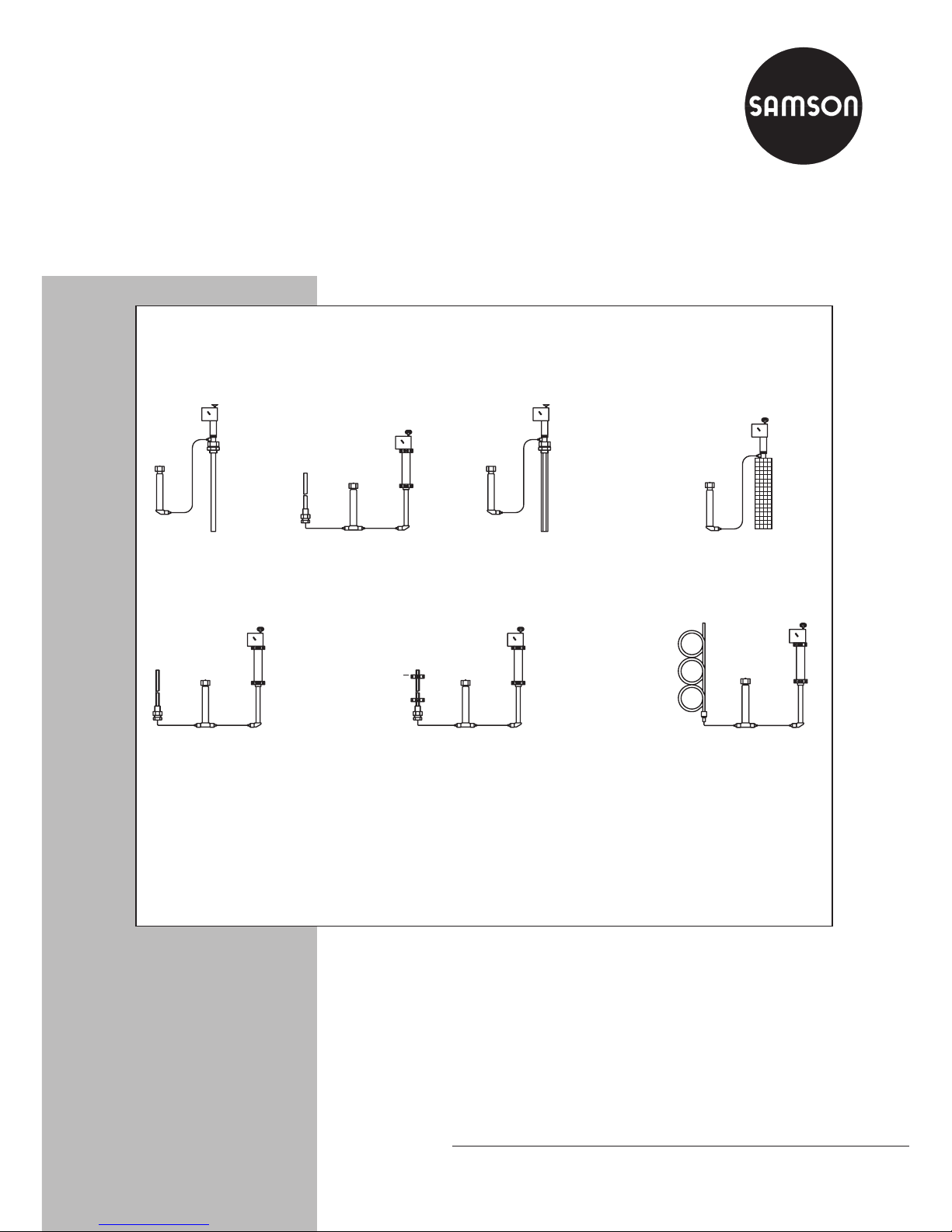
2.2 Types2233, 2234, and
2235 (air sensor)
Types2233 and 2234 are designed for in-
stallation in air heaters, air ducts, drying
cabinets, etc. Install the sensor from the out-
side into the room and secure it with a spe-
cial clamp (accessories). The entire length of
the sensor must be immersed in the air ow
to be regulated.
For Type2234, install the set point adjust-
ment in an easily accessible location.
Avoid locations with considerable ambient
temperature uctuations.
Type2233 with perforated cover is general-
ly used for installation in manufacturing fa-
cilities, living spaces, baths, etc.
Installation recommendations
−Mount the sensor protected by a perfo-
rated cover to a suitable location, if pos-
sible in the middle of the wall.
−Type2234 with clamps (or perforated
cover) is suitable for installation in dry-
ing chambers, dryers, air heaters, incu-
bators, etc. In case of forced air circula-
tion, install the sensor near the supply air
inlet. Mount the set point adjustment out-
side the room to be controlled in an easi-
ly accessible location. The set point ad-
justment must be exposed to a tempera-
ture that is as constant as possible.
−Type2235 is equipped with a tempera-
ture sensor to be calibrated on site. This
allows the measurement of almost all
temperature layers. Make sure the set
point adjustment for this sensor is in-
stalled outside the room to be controlled
in an easily accessible location. Avoid
locations with considerable ambient tem-
perature uctuations.
−When regulating the temperature in
greenhouses, make sure that the thermo-
stat and set point adjuster are not ex-
posed to direct sunlight. When the tem-
perature regulating system is shut down
during the summer, adjust a high set
point to protect the thermostat.
2.3 Capillary tube
ÎCarefully run the capillary tube (11)
without bending or twisting it and do not
expose to any temperature uctuations, if
possible.
NOTICE
!