2 Design and principle of
operation
Safety temperature monitors (STM)
The snap-action switch is triggered if the
temperature at the bulb rises above the ad-
justed set point. When the temperature falls
below the set point by approximately 8 K,
the switch returns to its original position.
The electric circuit is opened when the tem-
perature at the bulb falls below –20 °C. The
circuit is automatically closed again when
the temperature at the bulb rises above
–20 °C.
The circuit remains permanently open if the
measuring system is broken.
Temperature regulators (TR)
The snap-action switch is triggered if the
temperature at the bulb rises above the ad-
justed set point. When the temperature falls
below the set point by approximately 4 K,
the switch returns to its original position.
Safety temperature limiters (STL)
The snap-action switch is triggered and
locked if the temperature at the bulb rises
above the adjusted set point. When the tem-
perature falls below the set point by approx-
imately 10 %, the snap-action switch can be
unlocked manually.
The electric circuit is opened when the tem-
perature at the bulb falls below –20 °C. The
circuit is automatically closed again when
the temperature at the bulb rises above
–20 °C.
The circuit remains permanently open if the
measuring system is broken. It is not possi-
ble to unlock the device.
2.1 Typetesting
The thermostats are typetested by the Ger-
man Technical Inspectorate (TÜV) according
to DIN EN 14597.
Type DIN register number
5343 STW120908
5344 TR120808
5345 STB120708
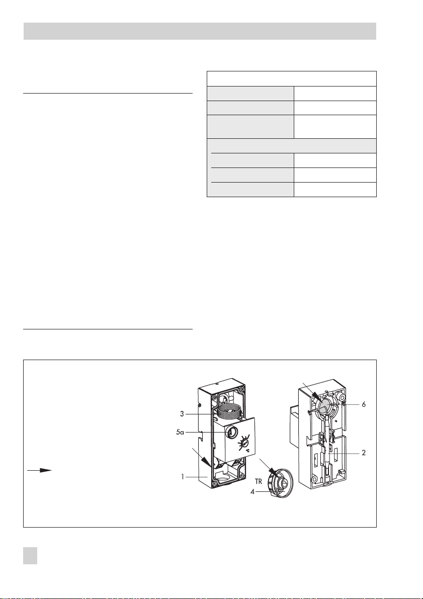
4EB 5206 EN
Design and principle of operation