SAMT START-S2XL User manual

Manuals and warnings
2002/95/EC
Time acquisition “real-time”, radio receiver included (HCS rolling code),
BPIDAPID
143 5 6 7
1110 12 13 14 1615 17 18 19 20 21
FUSE 4A
1 2 3 4
ON
Opening Limit Switch
Closing Limit Switch
STOP
FOTO
CLOSE
START
OPEN
LED L1
Functioning
2
P1
1 2 3 4
ON
1 2 3 4
DIP C
8 9
Opening Limit Switch
Closing Limit Switch
STOP
PHOTO-A / CLOSING
CLOSE
START
OPEN
12 Vac 200mA
BUS-DATA
COMMON
- NEGATIVE ANT.
+ POSITIVE ANT.
230 Vac NEUTRAL
EARTH
230 Vac PHASE
LIGHT 230Vac
LIGHT 230Vac
MOTOR COMMON
MOTOR OPEN
MOTOR CLOSE
CONTACT FLASH / SPY
CONTACT FLASH / SPY
12 Vac 200mA
Power Switch
433,92 Mhz
Radio receiver
“Man present” function with remote control. Intervention of photocell when closing, Stop. Courtesy Light
230 V Mono-phase control unit for rolling shutters, awnings, barriers.
230V AC Control Board

Foreword
This manual provides all the specific information you need to
familiarize yourself with and correctly operate your unit.
Read it very carefully when you purchase the instrument and
consult it whenever you have doubts regarding use and before
performing any maintenance operations.
Safety precautions
Environmental protection
measures
Information regarding the environment for customers
within the European Union.
European Directive EC 2002/96 requires that units
bearing this symbol on the unit and/or on the
packaging be disposed of separately from
undifferentiated urban wastes. The symbol
indicates that the product must not be disposed
of with the normal household wastes.
The owner is responsible for disposing of this product and
other electrical and electronic equipment through specific
waste collection facilities indicated by the government or local
public agencies. Correct disposal and recycling help prevent
any potentially negative impact on the environment and human
health. To receive more detailed information regarding disposal
of your unit, we recommend that you contact the competent
public agencies, the waste collection service or the shop where
you purchased the product.
Using the unit improperly and performing repairs or modifications
personally will void the warranty.
Nologo declines any responsibility for damages due to
inappropriate use of the product and due to any use other than
the use the product was designed for. Nologo declines any
responsibility for consequential damages
except civil liability for the products.
Small dictionary
Vac (alternate current)
Vdc (direct current)
FCA or FCO Opening Limit Switch
FCC Closing Limit Switch
NC Normally closed
NA Normally open
Contatto pulito Isolated contact
2
2
1230 Vac NEUTRAL
12
13
14
15
10
11
ESAHPcaV032
12 Vac 200mA
FCA OPEN MOTOR
FCC CLOSE MOTOR
PHOTO-A / CLOSING
3
4
5
LIGHT 230 Vac
LIGHT 230 Vac
MOTOR COMMON
6MOTOR OPEN
7MOTOR CLOSE
STOP
18
19
20
21
16
17
OPEN / START
BUS-DATA
COMMON
+ POSITIVE ANTENNA
CLOSE
- NEGATIVE ANTENNA
EARTH
8CONTACT FLASH / SPY
9CONTACT FLASH / SPY
12 Vac 200mA

1.00 Installation: Scheme of the control unit
M
1230 Vac neutral contact
EARTH
2230 Vac Phase
3230 Vac output for lamp without electronic
card . See paragraph 4.02
4
5230Vac common motor
6230Vac motor open
7230 Vac motor closes
8
Output for isolated contact without
flashing card or light
9
Output for isolated contact without
flashing card or for light. 230Vac lamp
with flashing card or with 230Vac card
when gate is moving
DIP A DIP B
143567
1110 12 13 14 1615 17 18 19 20 21
FUSE 4A
1234
ON
Opening Limit Switch
Closing Limit Switch
STOP
FOTO
CLOSE
START
OPEN
LED L1 TEST
Functioning
2
P1
1234
ON
1234
DIP B
89
Opening Limit Switch
Closing Limit Switch
STOP
PHOTO-A / CLOSING
CLOSE
START
OPEN
12 Vac 3mA
12 Vac 3mA
BUS-DATA
COMMON
- NEGATIVE ANT.
+ POSITIVE ANT.
230 Vac NEUTRAL
EARTH
230 Vac PHASE
8 - 9 CONTACT FLASH / SPY
3 - 4 EXIT NO FLASH
10 12 Vac 200mA Output
11
12 FCO Opening Limit Switch
13 FCC Closing Limit Switch
14 STOP input
15
PHOTOCELL–A input only activated
when closing, if it is working, reverse
totally and stop.
16 OPENING output / START control
17 CLOSING input / it makes the following
cycle: CLOSE-STOP-CLOSE
18 Bus - data system
19 Common contact for services and BUS
20 - Antenna negative pole
21 + Antenna positive pole
Red LED ( normally closed ) turned on: Opening Limit Switch close
LED L1 TEST: it indicates the right functioning of the control unit.
It should flash each second ( twice when rolling code) and it indicates
that the micro-processor is activated
LED green ( normally open) : it turned on when the contact opens
LED green ( normally open) it turned on when the contact closes
LED red ( normally closed ) turned on: STOP contact closed
LED red ( normally closed) turned on = FOTO contact closed
When the control unit is powered, the LED,
which are in the inputs, are turned on when
the input common contact is closed:
Normally the red led on the inputs:
Opening Limit Switches, Closing Limit Switches,
STOP , FOTO are turned on.
Normally the green led in the inputs:
START / OPEN are tirned OFF
I LED
3
433,92 Mhz
Radio receiver
Power Switch
230 Vac output for lamp with electronic
card . See paragraph 4.02
12 Vac 200mA Output
LED red ( normally closed ) turned on: STOP contact closed

4
1.01 Type of electrical wires
Depending on the installation, the type and number of devices installed, the number of cables needed can vary. The table below
shows the cables needed for a typical installation. The cables used in the installation must be IEC 60335 compliant.
DPower supply line Cable 3x1,5 mm
2
DMotor cable (if not equipped) Cable 4 x 1,5 mm
2
DFlashing signal Cable 2x1,5 mm
2
DAntenna Shielded cable type RG58
DKey selector Cable 3x0,5 o 0,75 mm
2
DPhotocell receiver Cable 4x0,5 o 0,75 mm
2
DPhotocell transmitter Cable 2x0,5 o 0,75 mm
2
1.02 Notes of connections
To guarantee operator safety and to prevent damaging the components, never make connections or insert wireless
receiver boards while the control unit is powered. Power the control unit through a 3 x 1.5 mm2 cable.
If the distance between the control unit and the ground system connection is more than 30 m,
a ground plate must be installed in proximity to the control unit.
If the motors do not have a cable, use the 4 x 1.5 mm2 cable (open + close + common + ground).
In connecting the part with an extremely low safety voltage, use cables with a minimum section of 0.5 or 0.75 mm2.
Use shielded cables if the length exceeds 30m and connecting the ground braid only from the side of the control unit.
Do not connect the cables in underground cases even if they are water-tight.
If they are not used, the inputs to the Normally Closed (NC) contacts must be jumpered to the common”
If the same input has more than one contact (NC), they are placed in series.
If they are not used, the inputs to the Normally Open (NO) contacts are left loose.
If the same input has more than one contact (NO), they are to be placed in series.
The contacts must be mechanical and free of any potential.
Remember that systems for automatic gates and doors must be installed by highly qualifi ed technicians only
and in full compliance with current law.

5
Description of the KIT version
The kit version includes
Box for Control Unit 115mm x 165mm x 65mm
Control Card
2 Channel receiver (START/OPEN and CLOSE)
230V AC Control Board

4 5 6 7
2.00 Connection of the motor
6
Pay attention not to invert the poles OPEN and CLOSE.
In case of doubts, put the gate manually in the middle.
Be ready to stop the gate with a STOP control.
Make sure that the control OPEN is really OPEN,
try to interrupt the photo-beams:if the gate starts closing,
the connection is not correct and you need to reverse the cables OPEN and CLOSE of the motor
Please note that you can hear the relay even if it is not connected,
while opening it sounds very fast, while closing it sounds very slowly.
2.02 Connection of the photocell FOTO-A inverting only when closing
The contact of the receiver of the photo-beam should be :
- Isolated from power tensions
- NORMALLY CLOSED
If you use more couples of photo-beams,
the connections should be serial.
The photo-beams interfere only when closing
provoking a total inversion.
If the input FOTO is not used, put the DIP 4
in ON and exclude FOTO in the DIPA
21 20 19 18 17 16 15 14 13 12 11 10
BUTTON: stop and forbit for a while the function of the control unit
until a new control.
SWITCH: keep the gate closed until a new control.
The connections of the safety devices prevue any
button or a normally closed contact .
In case of more safety devices, connect in serial.
If the input STOP is not used,
put the DIP 3 in ON and exclude STOP in the DIPA
2.03 Connection of the STOP with immediately intervention
21 20 19 18 17 16 15 14 13 12 11 10
3
COMMON
OPEN
CLOSE
COM.COM.
2.01 Connection of the signal light or lamp
4 5 6 73 8 94 5 6 73
Lamp
Connect the lamp LUCE -1 230vAC with flashing card.
Or a lamp with fix light when the gate is moving.
For courtesy light see paragraph 4.02 .
Connect the lamp LUCE -0230 without flashing card.

7
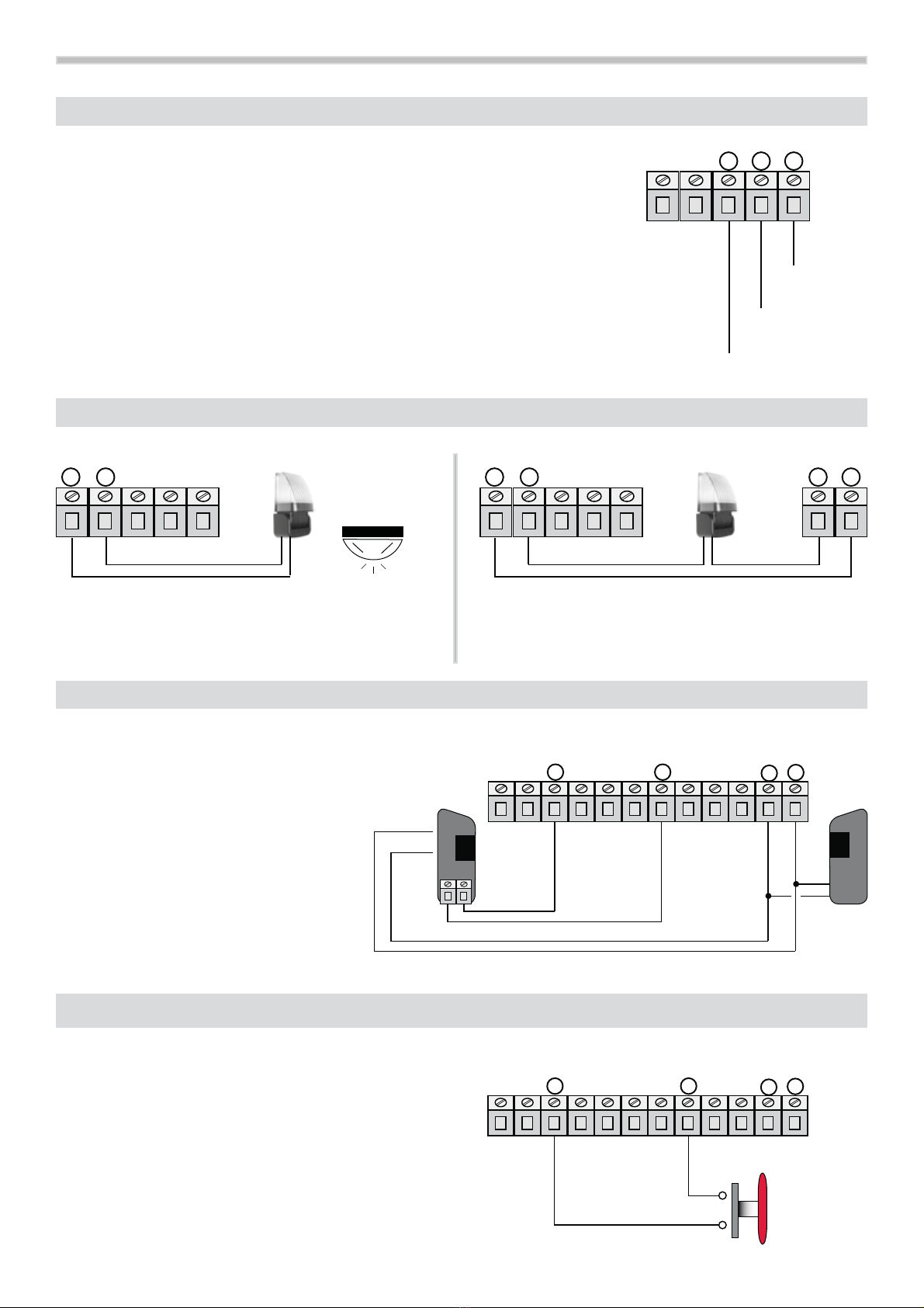
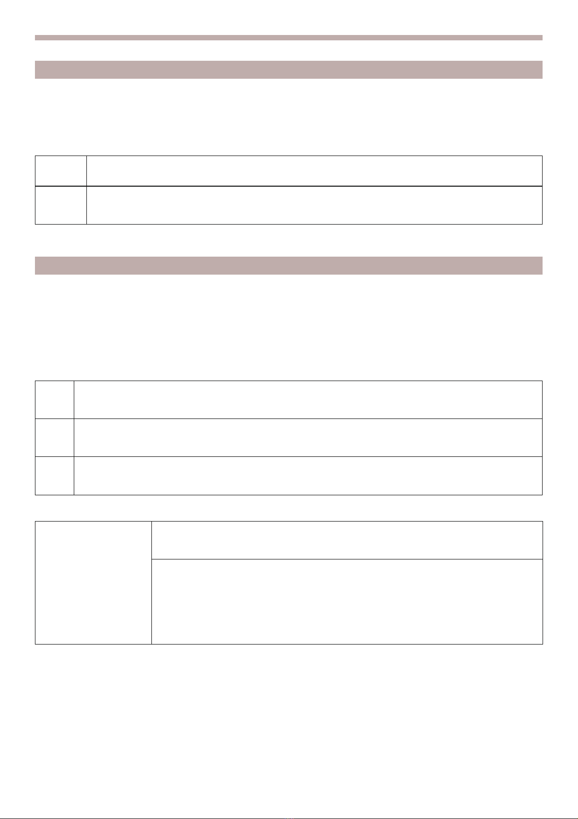
2.05 Connection of the opening limit switches and closing limit switches
OPEN
CLOSE
In the picture the limit switches are shown,
but in this control unit you can use separately.
So you can use for example “Opening limit switch” or
“Closing limit switch”.
The contacts of the limit switches are normally closed.
If the input of the FCA ( opening limit switches)
and FCC ( closing limit switches) are not used,
put the DIP 1 and 2 in ON and exclude FCA and FCC in the DIPA
21 20 19 18 17 16 15 14 13 12 11 10
nd closing limit switch
21 20 19 18 17 16 15 14 13 12 11 10
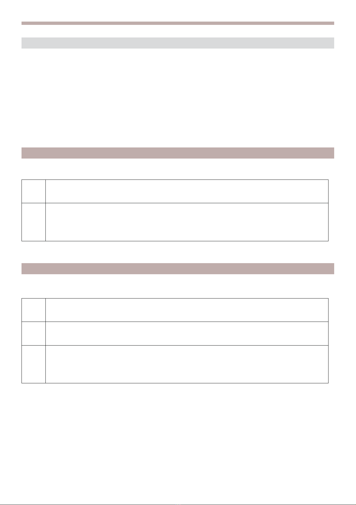
2.06 Connection of the antenna
If you use only a small cable for the antenna,
for the frequency 433.92 Mhz, cut it at 17cm
and connect it to the terminal board no.21
21 20 19 18 17 16 15 14 13 12 11 10
COM.
COM.
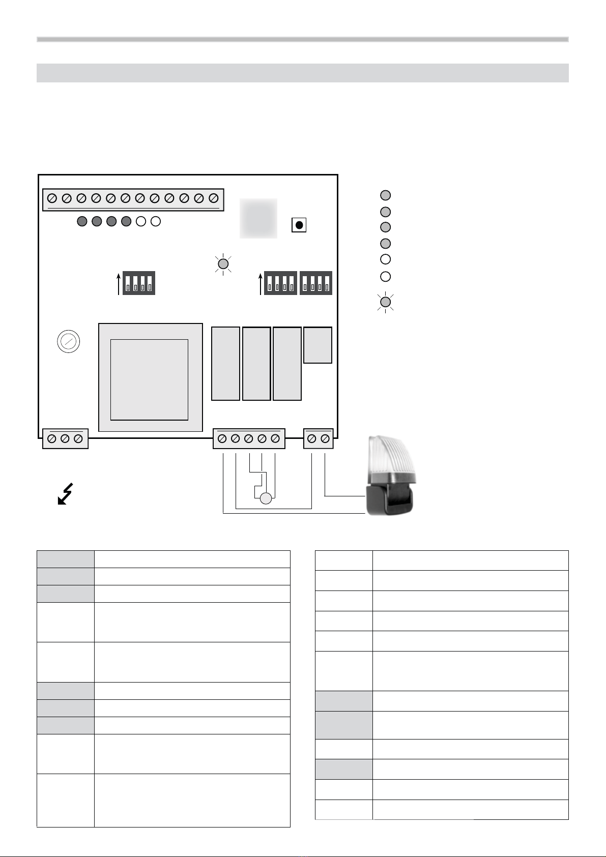
2.07 Check of the connection
Check the exactly tensionin the terminal boards, all NC red l.e.d. should be turned on.
When the control unitis powered , the lights L.E.D. which are in the inputs,are turnedon when there is a closing common contact.
Normally the red led in the inputs STOP-FOTO-FCC –FCA are always turned on.
Normally the green led in the control START – PARTIAL OPENING are turned off.
Look LED L1TEST when correct programmed, should flashes constantly or with a single/double flashing.
Check the safeties, the gate should go in the right direction, it should open firstly.
.
The connection of the opening control START (16-19) or closing (17-19)
can be done with any button or with a normally open contact.
In case of more devices, they should be serial connected.
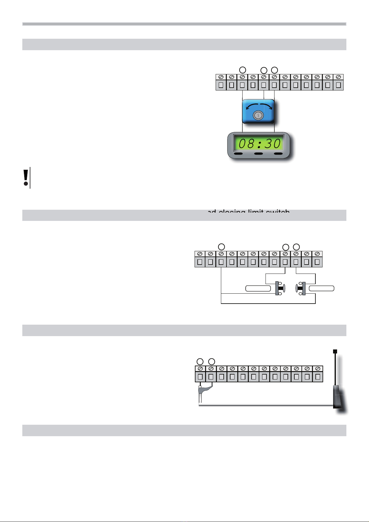
If you use the terminal board START (16-19) it is possible
to connect a TIMER to program the opening of the gate.
It is possible to use a timer with automatic re-closing or
in step-by-step function (see TIMER WITH STEP-BY-STEP FUNCTION)
The contact of the TIMER should be normally open, and the contact should
be closed when the gate is opening. If the opening connection is available,
the terminal board no.16 should be parallel connected.
TIMER WITH STEP-BY-STEP FUNCTION ( DIP B 1 OFF - 2 ON)
If you connect a timer in the input START ( no.16-no.19), the gate closes when the timer contact is in OFF position (open
contact) but only in case the gate is open and the timer is connected for more than 10 seconds .
2.04 Connection of the control OPENING AND CLOSING

The control unit dispose of a button PULSANTE P1 for different operation,
one is the cancellation of all codes inside the memory. To cancel make the following two steps.
The output of the control boards are not activated , eventually lights connections should be turned off.
This operation is possible only when the gate is closed.
1Press and keep pressed the button PULSANTE P IN THE CONTROL UNIT, LED L1 is lit up.
2
After 6 seconds LED L1 will turned off and you can release the button P1.
LED L1 will flash for 4 times then it will flash regularly to memorize fixed code.
(1 regular flash only see next paragraph) . The memory has been cancelled.
1Press and release the button PULSANTE P1 , LED L1 will lit for 6 seconds. Then
2In 6 seconds press and release button PULSANTE P1again,
LED L1 will flash once and it will lit for 6 seconds. Then
3In 6 seconds press and release button PULSANTE P1 again,
LED L1 flashes twice and then regularly as under described
LED L1 LED L1 Only for compatible fixed code
1 regular flash
The included receiver in the START S2XL can manage the major branded codes up
to 96bit, it memorize only the fixed part of the codes. Once you memorize the first code,
it can manage only the same type of code.
If the first remote control is a 12 bit ( for example dip-switch), the receiver will accept
only 12 bit codes of the same type. The HCS rolling code cannot be memorized.
3.01 Remote controls: code managing
To choose: which remote control should I memorize?
How will the receiver manage the codes?
START S2XL can manage fix and HCS rolling code, you can see how to memorize in the different ways.
The ouput of the control unit should be deactivated, eventually light connections should be turned off.
This operation is possible only when the gate is closed.
8
3.00
Remote control: cancellation of the memory

3.02 Remote controls: memorization of the codes
The control unit dispose of a button PULSANTE P1 to program the worling time and to memorize the code of the
remote controls. If you use a new FIXED CODE remote control like SMILE-C, make sure that all butoons have a
code otherwise you need to create a code.
1Press and release the button PULSANTE P1 in the control unit, LED L1 will lit for 6 seconds.
Then
2
In this 6 seconds push the button of the remote control which is associated to the contorl OPEN (START),
we suggest the 1st channel.
To confirm the right operation LED L1 will flash for 5 times and then regularly as at the beginning.
The control OPEN has been memorized
If LED L1 will not flash immediately for 5 times, it means that the memory is full and it cannot accept other codes.
Concerning the 20bit codes, the memory can learn maximum 22 different codes, if you need to learn more codes
we suggest you to put an additional receiver RX2 or RX4 with a capacity of 200/3000 codes.
If you are not sure that the memorization has been correctly start from point no.1 but before cancel the previous codes
in the receiver. See previous chapter “ cancellation of the memory”
This works with the logic DIP B 1 and 2 see “ Function logic”.
1Press and release the button PULSANTE P1 in the control board, LED L1 will li tfor 6 seconds. Then
2In these 6 seconds press and release the button PULSANTE P1 again, LED L1 will lit for 6 seconds. Then
3
In these seconds press the button of the remote control which should be associated to the control
CLOSE, we suggest the 2nd channel. This function is only possible in this sequence:
CLOSE-STOP-CLOSE and it cannot be changed.
To confirm the right procedure LED L1 will flash for 5 times and then regularly as at the beginning.
The code CLOSE has been memorized.
This operation is possible only in this sequence: CLOSE-STOP-CLOSE which it cannot be changed.
To memorize the first channel of the remote control with the control OPEN ( START) .
To memorize the control “ CLOSE” in the second channel
9

10
Dip 1 ON It excludes the connection of the Opening Limit Switch . And vice versa
Dip 2 ON It excludes the connection of the Closing Limit Switch. And vice versa
Dip 3 ON It excludes the connection of STOP. And vice versa
Dip 4 ON It excludes the connection of PHOTO-BEAMS. And vice versa
The control unit dispose of micro-switches DIPA and DIP B and DIPC which can activate or deactivate different functions to give
more safety.
4.00 Program of the DIPA to exclude the connections
1
23
4
1
23
4
1
23
4
1
23
4
Dip 1 ON Dip 2 OFF COLLECTIVE USE When opening and in pause time it doesn’t accept any other control.
It recloses automatically at the end of the pause time
Dip 1 OFF Dip 2 ON PARTIALLY
AUTOMATIC
Each control the sequence is: open-stop-close-stop-open ETC.
It doesn’t reclose automatically.
Dip 1 OFF Dip 2 OFF AUTOMATIC 1 Each control it inverts: open-close It reclose automatically
at the end of the pause time.
Dip 1 ON Dip 2 ON AUTOMATIC 2 Each control the sequence is open-stop-close-stop-open.
It recloses automatically at the end of the pause time.
This sequence is for the control START connected to the terminal board no.16 and for the programming of the remote controls.
To deepen go to the chapter “ REMOTE COLTROLS”
4.01 Program of the DIP B for the sequence START
1
23
4
1
23
4
1
23
4
1
23
4
Dip 3 ON It activate the “ Man Present “ Up function ( with a remote control ,too)
Dip 3 OFF It deactivate the “ Man Present “ and it works the working sequence of the dip1 and 2.
Dip 4 ON It activate the standard working time at 90 seconds with a pause time of 10 seconds.
Dip 4 OFF It deactivate the standard working time and it use the working time previously programmed .
To memorize the working time and the pause time with time acquisition “real time “ see chapter “ Memorization of the working time”
1
2
ON
3
4
1
23
4
1
23
4
1
23
4
Dip 1 - 4 Free program to create an address to control the control unit,
For Bus data System see next chapters.
4.02 Program of the DIPC for BUS-DATA SYSTEM. Courtesy light
1
23
4
Dip 1 IN the output of the terminal board no. 3 and 4 there is tension available from
the beginning of the closing up to 2 minutes after closing.
It is important to power the courtesy light.
1
23
4

11
If everything has been correctly connected, when turning on the red light of LED L1 TEST should flash,
while STOP, FOTO, FCA( opening Limit Switch), FCC (Closing Limit Switch) should lit up (if the gate is closed and if the closing
limit switch is connected, it should turned off) . LED START and PED (partial opening) are turned off.
The working time procedure is as follow. To execute such operation you can use START (open) or any device connected
to the terminal board 19-16 to open with START control or with a remote control ( previous memorized)
5.00 Turning on and learning of the control unit
1Put in OFF the micro-switches 3 and 4 of the DIP B. The gate is closed
2Power the control unit. The gate is closed.
3Push the control START ( everything connected to the input 16 or to
the first channel of the remote control ) from now it starts counting.
The gate opens, the relay sounds fastly.
The control unit counts.
4Push the button PULSANTE P1 and from now it memorize
the working time.
5When the gate opens at the choosen point, press button
PULSANTE P1. If you use the limit switch you don’t need to press P1. The gate stops.
6Let the time goes for the opening time. The gate is in PAUSE TIME:
The relay light stops.
7Press the button PULSANTE P1 to start closing. The gate starts closing,
the relay sounds slowly.
8
Program the dip for the personalized program again. Programming is over.
9
The gate is closed.
Turn off the control unit, close the gate,
put in OFF the terminal board no. 3 and 4 of DIPB
and power the control unit again.
Wait until the gate stops automatically. The gate is closed.
1
23
4
DIP B
When you use the limit switches you can use the standard working time of the control unit.
The programming can be activated with micro-switch 4 of DIP B.
Fixed working time up to 90 seconds. Fixed pause time up to 10 seconds.
As mentioned, if you need to personalized the pause time it is necessary to programm
as described in the chapter 5.01. Then to personalized the pause time see the chapter 4.01.
5.02 Time programming with limit switches
123
4
DIP B
During the programming you can hear the relay even it is not connected, when opening it sounds fastly
(1-2 seconds) when closing it sounds slowly (1 second)
If the flashing light has been connected (terminal board no. 3-4-8-9),
it flashes fastly when opening ( 1-2 seconds) and slowly when closing ( 1 second).
Go forward with the personalized programming see previous chapter 4.01
5.01 Working time with or without limit switches

12
6.00 Declaration of CE conformity
(according to EC Directive 98/37, Attachment II, part B)
The undersigned Ernestino Bandera,
Administrator
DECLARES THAT:
Busto Arsizio, li 05 april 2010
The Adminitrator
Ernestino Bandera
THE PRODUCT COMPLIES with what is outlined in the European Community directive:
EC 98/37 (EEC 89/392 modified)
EC DIRECTIVE 98/37 ISSUED BY THE EUROPEAN PARLIAMENT AND
COUNCIL on June 22, 1998 harmonizing the legislation of the member countries
regarding machinery.
Reference: Attachment II, part B (EC Declaration of Conformity issued by the manufacturer).
THE PRODUCT COMPLIES
with what is outlined in the following European Community
directives, as modified by EEC Directive 93/68 issued by the
EUROPEAN COUNCIL on July 22, 1993
73/23/CEE
EEC DIRECTIVE 73/23 ISSUED BY THE EUROPEAN COUNCIL on February
19, 1973 harmonizing the legislation of the member countries regarding electric
materials for use within certain voltage limits.
Reference to harmonized standards: EN 60335-1
89/336/CEE
EEC DIRECTIVE 89/336 ISSUED BY THE EUROPEAN COUNCIL on May 3,
1989, harmonizing the legislation of the member countries regarding
electromagnetic compatibility.
Reference to harmonized standards: EN 61000-6-2 EN 61000-6-3
THE PRODUCT COMPLIES
with the essential requirements of article 3 of the following
European Community Directive, for the use for which the
product is designede
1999/5/CE
EC DIRECTIVE 1999/5 ISSUED BY THE EUROPEAN PARLIAMENT AND
COUNCIL on March 9, 1999 regarding wireless units and telecommunications
terminals and their reciprocal recognition.
Referring to the standard norms: ETSI EN 300 220-3 ETSI EN 301 489-1 ETSI EN 301 498-3
The directive 98/37/Ce remind that it is not allowed the function of the product until the machine, for which
the product is included, is not indentify and declared conformed to the 98/37/ce directive.
Company: EB TECHNOLOGY SRL
Adress: Corso Sempione 172/5
21052 Busto Arsizio VA Italia
Product’s name: START-S2XL
230 Vac mono-phase
control unit
EB TECHNOLOGY S.r.l.
Corso Sempione 172/5,
21052 Busto Arsizio VA Italia
tel. +39 0331.683310
fax.+39 0331.684423
posta@ebtechnology.it
www.ebtechnology.it
NOLOGO S.r.l.
via Cesare Cantù 26,
20020 Villa Cortese MI Italia
tel. +39 0331.430457
fax.+39 0331.432496
www.nologo.info
2002/95/EC
5R+6
&203/,$17
Other SAMT Garage Door Opener manuals
Popular Garage Door Opener manuals by other brands

Delta Electronics
Delta Electronics VFD-DD Series user manual

OSCO
OSCO Model T Safety, installation and service manual

Rollerdor
Rollerdor RD55 installation guide

Gatekeeper
Gatekeeper SKC-600DC owner's manual

Wayne-Dalton
Wayne-Dalton 8000 Series Installation instructions and owner's manual

Cardin
Cardin 100/SL324EBSB instruction manual