Samyung ENC SMR-7200 User manual

1
Contents
Chapter 1. Overview
1.1 Function 4
1.2 Feature 4
1.3 Composition 4
1.4 Construction 6
1.5 Specifications 8
1.5.1 General 8
1.5.2 Antenna (RSU-7200) 8
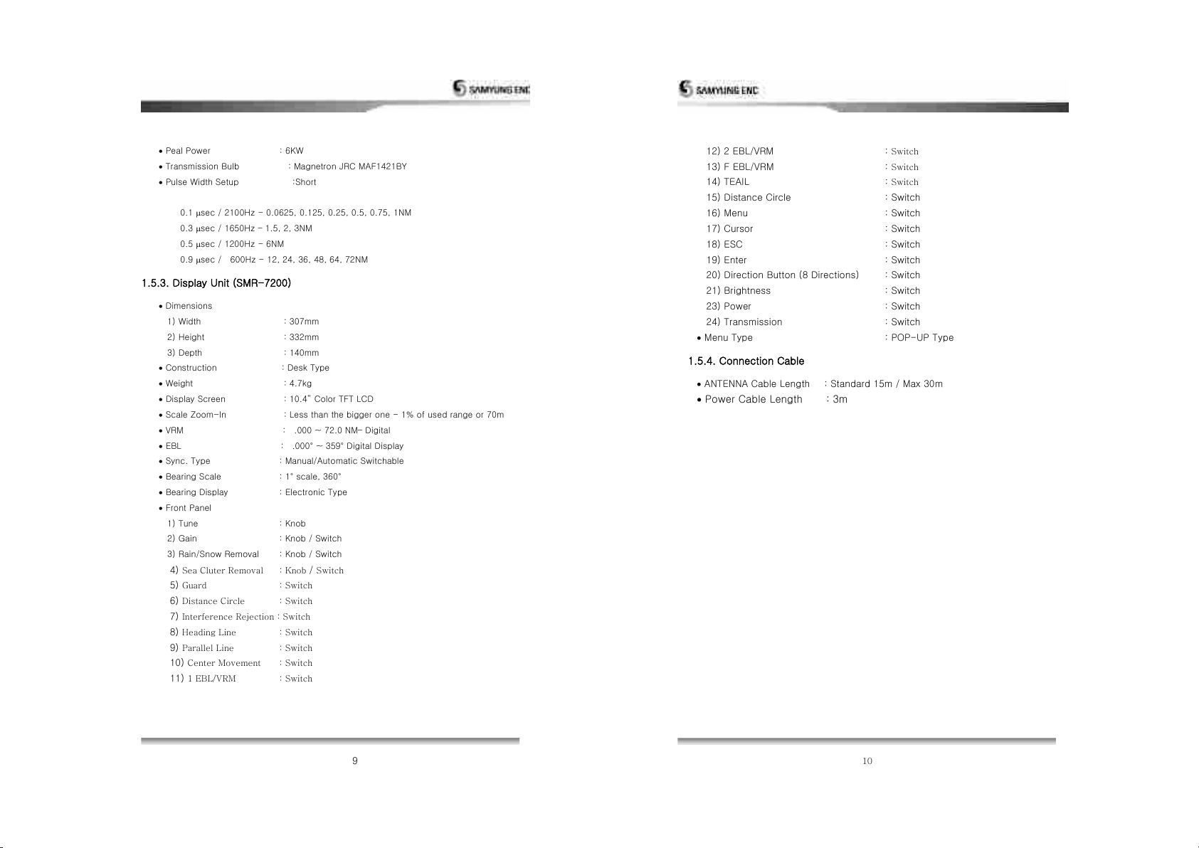
1.5.3 Display Unit (SMR-7200) 9
1.5.4 Connection Cable 10
Chapter 2. How to operate panel and menu
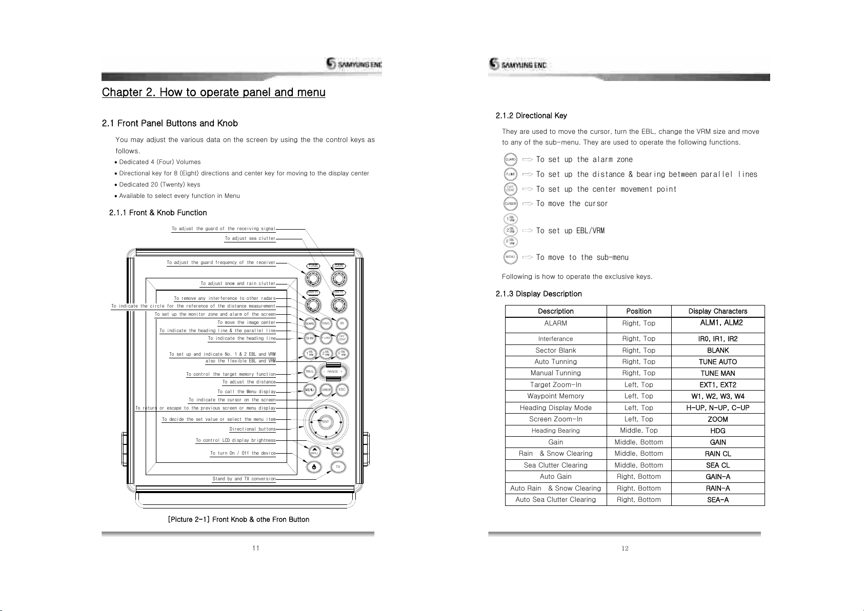
2.1 Front Panel Buttons and Knob 11
2.1.1 Front Function 11
2.1.2 Directional Key 12
2.1.3 Display Description 12
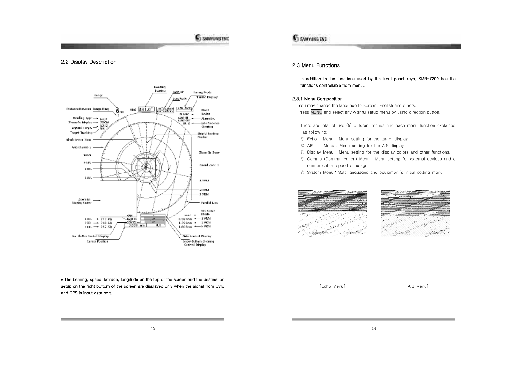
2.2. Display Description 13
2.3. Menu Functions 14
2.3.1 Menu Composition 14
2.3.2 MENU Functions 16
Chapter 3. How to operate the unit
3.1 General Idea 22
3.1.1 Power Input and Operation 22
3.1.2 Tuning Control 22
3.1.3 Image Control 23
3.1.4 Power Off 23
3.2 S t a n d - b y f o r P r o c e s s i ng 2 3
3.2.1 B r i g h t n e s s C h a n g e 23
3.2.2 Language Selection 23
3.3 Basic Operation 23
3.3.1 TX 23
3 . 3 . 2 T X S t o p 23
3.3.3 Tuning Cont rol 2 3
2
3.3.4 G a in C on t r o l 2 3
3.3.5 R a i n / S n o w R e m o v a l 2 5
3 . 3 .6 T o o p e r a t e t h e a l e r t f u n t i o n 26
3.3.7 To eliminate/display the scale of Range Ring 28
3.3.8 To remove the Radar Interference 28
3.3.9 To elemina③e ③he Ship② Heading Line 29
3.3.10 To use the parallel line 29
3.3.11 To move the center of own ship 29
3.3.12 To measure the distance and bearing to the Target 29
3.3.13 To change distance unit 30
3.3.14 To change the way of direction symbol 31
3.3.15 To change the way of bearing display 34
3.3.16 To change the way of displaying bearing ine/cursor 34
3.3.17 To compensate the magnetic 34
3.3.18 To measure the time to the target 35
3 . 3 . 1 9 T o d i s p l a y t h e W a y p o i n t … … 35
3 . 3 . 2 0 T o d i ② p l a y ③ h e o ③ h e ① ② h i p ② ③ ① a c k l i n e 36
3.4 Connection to the external navigation equipment 36
Chapter 4. Screen view
4.1 The distance from the target to the height of target 38
4.2 Reflection from the target 39
4.3 Wave Path 39
4.3.1 Reflection of sea level 39
4.3.2 False Image 40
Chapter 5. Installation
5.1 Overview 41
5.2 Installation of Antenna 41
5.2.1 Selection of the installation place 41
5.2.2 How to install Antenna 42
5.2.3 Connection to Equipment cable 43
5.3 DISPLAY SET-UP 45
5.3.1 Location for installation 45
5.3.2 How to Install 45
5.3.3 Power Cable connection 45
5.4 Installation check 45

3
5.5 Operation check 45
5.6 Initial Installation 46
5.6.1 Initial Installation 46
5.6.2 TUNE-R SET (Tuning Set) 47
5.6.3 TUNE SET (Tune Level Set) 47
5.6.4 Vide o ADJ 47
5.6.5 MBS ADJ 47
5.6.6 Tune ADJ 48
5. 6. 7 MT- RP M AD J 48
5.6 . 7 S TC C u rv e m i n 48
5.6.8 Upgrading software 48
5 . 6 . 9 S e t t i n g 48
5.6.10 Factory defult set 48
Chapter 6. Maintenance
6.1 General Maintenance 49
6.1.1 Cleaning 49
6.1.2 Check out the tightness of screw, bolt 49
6.1.3 Check the cabling 49
6.2 Antenna 49
6.2.1 OpenArray 49
6.2.2 Bracket 50
6.3 Display 50
6.3.1 Cleaning of a Display Screen 50
Chapter 7. Installation drawing and circuit diagram
Chapter 8. WARRANTY INFORMATION
4
Chapter 1. Overview
1.1 Function
This equipment is a small-sized raster smayning Radar, composed of OpenArray
type transceiver with 6 KW Transmitting power and 10.4 inch color TFT LCD
monitor.
This radar complies with the regulation of frequency law.
1.2 Feature
Antenna Unit
It emits the miscrowave toward targets by 4(four)-step pulse widths according
to the radar scale and transfers the image signals to the monitor that are made
by converting the reflected signals to 2(two)-step receiver band.
Transmission Output: 6KW
Max. Range : 72NM
Display Unit
SMR-7200 monitor is designed to receive the input signal from Antenna and
to display at the optimum conditions on the TFT LCD screen, based on the
SAMYUNG② be②③ digi③al ②ignaling ③echnology.
10.4 colo① TFT LCD, High Re②ol④③ion of 640 X 480
One-touch keys dedicated to every function
10 (ten)-step LCD brightness adjustments
The input of the external navigational devices such as Gyro or NMEA 0183 enables it
to display the own ship position and the destination
1.3 Composition
Composition and Power Supply
Model
Antenna unit
Display unit
Power supply
SMR-7200
RSU-7200
SMR-7200
DC 24V
The models are named in English as follows
Antenna : ANTENNA UNIT
Display : DISPLAY UNIT (DC24V : FUSE 5A)

5
Components
Description
Qy
Samyung CODE
Remark
Manual
1
SMR-7200-ME
ANTENNA-DISPLAY CABLE
1
RSU-7200-15M
15m
POWER CABLE
1
ACC-CAB-010
3m
SURGE CABLE
1
STR-595
3m
6
1.4 Construction
1200
386
466
[Pic. 1.1] RSU-7200 External Diagram

7
140
138 138
SCANNER
265
133 133
258
POWER
DOWNLOAD
NMEA
FUSE(7A)
EARTH AIS
EXTENSION
67
322
303
307
293 25
4-M6
194
[Pic.1.2] SMR-7200 External diagram of Display
8
1.5 Specification
1.5.1. General
Display Type : RASTER SMAY type
Display Screen 섭 10.4 Colo① TFT LCD, Vertical Display
Display Color : GREEN, YELLOW, RED,WHITE, COLOUR
Display Range : 0.0625, 0.125, 0.25, 0.5, 0.75, 1, 1.5, 2, 3, 6,
12, 24, 36, 48, 64 ,72NM
Distance Resolution : within 30m
Min. Detection Range : within 25m
Bearing Accuracy 섭 ±1°
Bearing Resolution : 2.1°
Bearing Input : True Bearing / Magnetic Bearing
Environmental Condition
1) Temperature : Antenna -25℃ ~ +55℃
: Display -15℃ ~ +55℃
2) Relative Humidity : Antenna - below 섬5% on 35℃
: Display - below 섬5% on 35℃
3) Relative Wind Speed : 51.5m/sec (100knots)
Power Consumption : 85W
DC Power : DC18V ~ DC36V
Preheating Time : 90 Sec.
Preaction : within 3 Sec.
1.5.2. Antenna(RSU-7200)
Dimensions
1) Diameter : 1200mm
2) Height : 386mm
Weight : 25.0Kg (without cable)
Plane of Polarization : Horizonal Target Wave
Polar Pattern
1) Horizontal Beam Width: 2.0°
2) Ve①③ical Beam Wid③h섭 25°
3) Side Lobe Level : Below -21dB
Revolution : Approx. 24 R/Min
TX Frequency 섭 섬410±30MHZ
Emission Type : P0N

9
Peal Power : 6KW
Transmission Bulb : Magnetron JRC MAF1421BY
Pulse Width Setup :Short
0.1 sec / 2100Hz - 0.0625, 0.125, 0.25, 0.5, 0.75, 1NM
0.3 sec / 1650Hz –1.5, 2, 3NM
0.5 sec / 1200Hz - 6NM
0.9 sec / 600Hz - 12, 24, 36, 48, 64, 72NM
1.5.3. Display Unit (SMR-7200)
Dimensions
1) Width : 307mm
2) Height : 332mm
3) Depth : 140mm
Construction : Desk Type
Weight : 4.7kg
Display Screen : 10.4 Colo① TFT LCD
Scale Zoom-In : Less than the bigger one - 1% of used range or 70m
VRM : .000 ~ 72.0 NM–Digital
EBL : .000° ~ 35섬° Digital Display
Sync. Type : Manual/Automatic Switchable
Bearing Scale : 1° ②cale, 360°
Bearing Display : Electronic Type
Front Panel
1) Tune : Knob
2) Gain : Knob / Switch
3) Rain/Snow Removal : Knob / Switch
4) Sea Cluter Removal : Knob / Switch
5) Guard : Switch
6) Distance Circle : Switch
7) Interference Rejection : Switch
8) Heading Line : Switch
9) Parallel Line : Switch
10) Center Movement : Switch
11) 1 EBL/VRM : Switch
10
12) 2 EBL/VRM : Switch
13) F EBL/VRM : Switch
14) TEAIL : Switch
15) Distance Circle : Switch
16) Menu : Switch
17) Cursor : Switch
18) ESC : Switch
19) Enter : Switch
20) Direction Button (8 Directions) : Switch
21) Brightness : Switch
23) Power : Switch
24) Transmission : Switch
Menu Type : POP-UP Type
1.5.4. Connection Cable
ANTENNA Cable Length : Standard 15m / Max 30m
Power Cable Length : 3m

11
Chapter 2. How to operate panel and menu
2.1 Front Panel Buttons and Knob
You may adjust the various data on the screen by using the the control keys as
follows.
Dedicated 4 (Four) Volumes
Directional key for 8 (Eight) directions and center key for moving to the display center
Dedicated 20 (Twenty) keys
Available to select every function in Menu
2.1.1 Front & Knob Function
Stand by and TX conversion
EBL
VRM
TRAIL
RAIN CL
TUNE
BRILL
SHM
To set up and indicate No. 1 & 2 EBL and VRM
To decide the set value or select the menu item
To return or escape to the previous screen or menu display
To indicate the cursor on the screen
To control the target memory function
To indicate the heading line & the parallel line
To set up the monitor zone and alarm of the screen
To indicate the circle for the reference of the distance measurement
To remove any interference to other radars
To adjust the guard frequency of the receiver
also the flexible EBL and VRM
To turn On / Off the device
To control LCD display brightness
Directional buttons
To call the Menu display
To adjust the distance
To indicate the heading line
To move the image center
To adjust snow and rain clutter
1
To adjust the guard of the receiving signal
To adjust sea clutter
BRILL
ENT
TX
- RANGE +
ESC
OFF
CENT
IR
F
EBL
VRM
2
P.LINE
RING
EBL
VRM
SEA CL
GAIN
[Picture 2-1] Front Knob & othe Fron Button
12
2.1.2 Directional Key
They are used to move the cursor, turn the EBL, change the VRM size and move
to any of the sub-menu. They are used to operate the following functions.
To set up the center movement point
To set up the distance & bearing between parallel lines
To set up the alarm zone
To move to the sub-menu
To set up EBL/VRM
MENU
2VRM
EBL
FVRM
EBL
To move the cursor
CENT
OFF
1EBL
VRM
Following is how to operate the exclusive keys.
2.1.3 Display Description
Description
Position
Display Characters
ALARM
Right, Top
ALM1, ALM2
Interferance
Right, Top
IR0, IR1, IR2
Sector Blank
Right, Top
BLANK
Auto Tunning
Right, Top
TUNE AUTO
Manual Tunning
Right, Top
TUNE MAN
Target Zoom-In
Left, Top
EXT1, EXT2
Waypoint Memory
Left, Top
W1, W2, W3, W4
Heading Display Mode
Left, Top
H-UP, N-UP, C-UP
Screen Zoom-In
Left, Top
ZOOM
Heading Bearing
Middle, Top
HDG
Gain
Middle, Bottom
GAIN
Rain & Snow Clearing
Middle, Bottom
RAIN CL
Sea Clutter Clearing
Middle, Bottom
SEA CL
Auto Gain
Right, Bottom
GAIN-A
Auto Rain & Snow Clearing
Right, Bottom
RAIN-A
Auto Sea Clutter Clearing
Right, Bottom
SEA-A

13
2.2 Display Description
The bearing, speed, latitude, longitude on the top of the screen and the destination
setup on the right bottom of the screen are displayed only when the signal from Gyro
and GPS is input data port.
14
2.3 Menu Functions
In addition to the functions used by the front panel keys, SMR-7200 has the
functions controllable from menu..
2.3.1 Menu Composition
You may change the language to Korean, English and others.
Press MENU and select any wishful setup menu by using direction button.
There are total of five (5) different menus and each menu function explained
as following;
◎Echo Menu : Menu setting for the target display
◎AIS Menu : Menu setting for the AIS display
◎Display Menu : Menu setting for the display colors and other functions.
◎Comms (Communication) Menu : Menu setting for external devices and c
ommunication speed or usage.
◎System Menu : Sets languages and equipments initial setting menu
[Echo Menu]
[AIS Menu]

15
[Display Menu]
[Communication Menu]
[System Menu]
[Initial Display]
16
2.3.2 Menu fucntions
2.3.2.1 Echo Settings
•Target track
This function is to track target and will display the target during set value
of RPM and will change colour at different levels leaving targets trail
This function will operate by pressing TRAIL. RPM may be adjusted from
Off to 4. Current setting status of W1~W2will be displyed on the upper
left corner of the screen
•Target boost
Set and adjust the target boost size with two (2) different levels.
•Palette Color Selection
User may select a favorite color from five (5) different colors of the target.
Example) Black-Multi: Black background color with any color of target.
•Color removal
You may remove the target color displayed, by the level from 0~16.

17
2.3.2.2 AIS Setting
•Display
May decide to display AIS or not.
•Colors
Selecting a color of AIS target; you may choose Green, Red, Blue,
White, or Black.
•CPA, TCPA (AIS Alarm Setting)
To set the collision alarm of AIS target. CPA is the distance setting and
TCPA is setting for estimated time before collision.
(CPA Menu) (TCPA Menu)
18
2.3.2.3 Display setting
•Mode
This menu allows to display bow, N-UP, C-UP and True Motion.
Bow mode only available when there is no external
signal, If there is an external signal of bow, it is available to select N-UP,
C-Up and True Motion mode
※Course means the waypoint set externaly
•Color
Select the colour between white, green, red for letters.

19
•FULL SCREEN
Target display gets displayed as FULL SCREEN
•Distance setting
You may set the distance unit from 0.0625, 0.125, 0.25, 0.5, 0.75, 1,
1.5, 2, 3, 6, 12, 24, 36, 48, 64 to 72 but when 0.0625 is not available
to use with km(kilometers) - mode.
•Zoom
This function is to zoom up and may zoom up to x 2 and
shows on the left or right bottom corner of the display
There are two display functions, Cursor Lock and Cursor Float
Cursor Lock : Zooms up the area around the cursor you have entered.
Cursor Float : Zoom up where the cursor is.
20
•Sector Blank
You may set Sector Blank in the radius 360˚by 1 degree.
It will be displayed with blue broken lines.
•Compass
You may turn on/off the compass function in the screen.
•North line
You may turn on/off the North line in the screen.
•Way point
You may turn on/off the way points from other equipment.
•EBL/CSR
You may select EBL/CSR to be Relative or True.
•Alpha Blend
You may set transparency of POP-UP menu between 50 to 100.

21
2.3.2.4 Communication setting
•NMEA0183-Port
This is a menu to set NMEA0183 port, you may check the transmission
speed and communication status. It provides Communication speed at
4800, 9600 and 38400.
Unit will display the communication status coming from the external
equipment.
•AIS
A function to check the communication condition to other equipment.
•GPS Input
A function to select GPS input port.
•Heading Source
It is a function which selects AIS heading standard as HDT or COG
22
2.3.2.5System setting
•Language setting
User may select a language
•Distance unit
You may choose among nm, mi, km
•Compass Type
You may select radar image with true heading or self heading.
Self adjustment is to adjust information of self heading.
•Tuning
You may set Auto/Manual a way of setting TX and RX.
•Installation Setting
A function to set equipment, please refer to 5.6.
※The unit is not activated once power has been input, please refer to
5.6.1 Initial Setting Menuto activate the equipment.
•Simulation
A function to check operation without antenna unit
•Key beep
You may turn on/off the beep.

23
•STC Curve
The following drawings show the curve between Distance to Gain
shown as the following drawings.
You must set the figures considering the reflected wave on surface of
the sea ②③a③④② ca④②ed by an③ennas installation location.
On average, antenna is installed at the height of 5m, when waves
height is at 1m, the setted value must be at Curve 1.
2~4, is when wave height at 2~4m, where reflected wave on surface
of the sea is severe.
If antennas at height of 10m and wave at 1m, the curve must be set
as 2.
24
Chapter 3. How to operate the unit
3.1 General Idea
3.1.1 Power input and Operation
1. Power input
To power on, press POWER button.
After power on, Count Down Timer is displayed on SAMYUNG Logo screen,
it will be on stand-by status in 1 min. 30 secs.
As the TX time is consolidated and displayed, user may judge the ideal time
for repair..
It indicates the version of the program.
[Refer] When unit does not turn off due to programme failure,
Please push OFF switch for 10 seconds so that you may shut it down
by force.
2. TX
Press button to enable the transmission at the stand-by status.
Press button again to convert the TX status to the stand-by status.
3.1.2 Tuning control
It is required to control the tuning of the unit both manually and automatically.
The conversion is selectable in the setup of MENU.
For the automatic tuning, Auto Tuning i② di②played nex③ ③o ③he ③④ning bar.
1. Change tuning mode
Menu System Tuning Auto / Manual Input Return
2. Control tuning volume
In case of tha manual tuning mode, turn the volume to adjust to the biggest
image.
Adjust to the maximum movement of the tuning bar.
In case of the automatic tuning mode, it is needless to turn the volume.
If image doe②n③ appea①, adj④②③ ③he volume again or turn the volume of
/(rain/snow) removal.

25
3.1.3 Image control
the volume of the tuning/gain of (sea clutter),
(rain/snow), removal to display the optimum image.
3.1.4 Power off
1. Stop transmission (TX).
Push T X key to be ready to transmit.
2. Turn off the Power.
Push POWER key for 3 seconds then power will be turned off.
Ex) A complete disconnection of power is necessary when unit is not in use
for long as parts for power supply are under operation even the power has been
turned of.
3.2 Stand by for processing
3.2.1 Brightness change
Press brightness key.
Push ▲key to brighten the screen, push ▼key to darken the screen.
You may adjust in 10 levels
3.2.2 Language Selection
Menu System Languange Select users language Input Return
Select language.
3.3 Basic Operation
3.3.1 TX
Press T X button, it will be converted to TX from the stand-by status.
3.3.2 TX Stop
Press T X button again at the TX, it will be the stand-by status.
26
3.3.2.1 STC Curve
The following drawings show the curve between Distance to Gain
shown as the following drawings.
You must set the figures considering the reflected wave on surface of
the sea ②③a③④② ca④②ed by an③ennas installation location.
On average, antenna is installed at the height of 5m, when waves
height is at 1m, the setted value must be at Curve 1.
2~4, is when wave height at 2~4m, where reflected wave on surface
of the sea is severe.
If antennas at height of 10m and wave at 1m, the curve must be set
as 2.
3.3.3 Tuning Control
Please refer to [3.1.2 Tuning Control].

27
3.3.4 Gain control
Turn gain key.
When you turn key left, decreases the gain, when you turn right,
increases the gain.
The optimum gain
Is when the targets ECHO display is at its maximum size, and when close by
targets are not touching on ECHO display
감도가 낮아 영상이 작다. 감도가 최적이다. 감도가 높아 2개의
영상이 붙었다.
Auto gain setting
When you push the switch in the gain volume, it will be displayed AUTO in
the bottom centre of the screen, it will be displayed GAIN-A in the right
bottom corner of the screen.
This function adjusts the gain at its optimum level, however may be affected
by environment.
ATTENTION
※It should be always observed by adjusting the optimum conditions.
※If the gain is too low, the targets may not be displayed.
※If too high, it may be an obstade in observation due to the noise increase on the display.
Small image by low gain
Optimum gain
2 Images contact by
high gain
28
3.3.5 In order to remove the interference of rain/snow
!
Under heavy rain/snow, the target may be difficult to analyze since ECHO
(Rain Clutter) caused by rain and snow may be displayed.
Turn Rain CL volume right to remove the echo image by snow and rain.
Reflected wave of rain/snow Removed rain/snow
(Target is restricted, too.)
Auto setting rain/snow
When you push the switch in the volume for removal rain/snow, AUTOwill
be displayed in Rain CL in the bottom center of the screen, and RAIN-A will
show on the bottom right corner of the display
This function is only to use under circumstances where the user wants to
automatically remove the snow/rain. Hence do not use this function if not
required as it will make target smaller than usual.
※Too much adjustment of rain/snow removal will restrain the target of shipsor
hazards as well as any images by rain/snow. This can be the cause of image
analysis.
※In case of use of rain/snow removal, the optimum conditions shoud alwaysset
up..
ATTENTION

29
3.3.6 To remove the interference of Sea Level Wave caused by the Sea Wave
!
When the wave becomes high due to heavy wind, the ECHO(Sea clutter)
due to the wave is displayed on the screen, then it will be difficult to detect
the image of the target.
Turn Sea Clutter key to the right to remove the echo image by wave.
The status that shows Sea Level Reflection The status that shows Sea Level Reflection
is strong due to Wave. is being suppressed.
(The target is also suppressed)
Auto Sea Clutter removal setting
When you switch on Sea Clutter removeAUTOwill show in the
Centre of bottom of screen, and SEA-Awill show in the bottom right corner
of the screen.
This function automatically sets the optimum display, however it is not
necessary to set it when theres no need to remove the Sea Clutter as the target will
be shown smaller than usual.
ATTENTION
※If you set the removal function of Sea Level Wave up to removal of all Sea Level
Reflection at short distance, it causes intereference in detecting images due to the
target of vessel and dangerous things as well as the wave images being suppressed.
※When you use the removal function of Sea Level Wave, you make sure it should be the
optimistic set of suppression
30
3.3.7 To operate the alert function
Set the guard zone in order to use the alert.
Guard Zone means [Zone] to be set on PPI screen
1. Guard Zone Setting
Place the cursor on the location you wish to set.
Press the Guard key
POP-UP Menu will be appeared to set up two different guard zones on the
screen.
Select incursion or separation of guard zone.
Incursion means the target enters into the zone and sepatation means the
target come out of the zone. In each case, the alert sound will come out.
Select Ring or Fan
Ring function will create ring-shaped guide zone and Fan function will create
Fan-shaped guard zone.
Press Adjust and then move the cursor to set up the guard zone.
Press the input key.
After a desired guard zone is done then exit
2. Occurrence and Stoppage of the alert sound
After setting up the guard zone, the alert sound will come out once the target
enter into the zone.
To stop the alert sound, press any key on the device.
3. Termination of the alert
To terminate the alert status, press the alert key and then select the alert zone
off.

31
3.3.8 To eliminate/display the scale of Range Ring
1. Press the Range Ring Key
The brightness of ON/OFF will be adjusted.
3.3.9 To eliminate the radar interference
Rada ① In③e①fe①ene mean② Micowave ③①an②mi③ed by o③he① ②h ip ② Rada①
directly which affects own ships Radar air line hence gets displayed on PPI screen.
1. Press the Interference removal key
Whenever pressing button, it marks with IR-1, IR-2, IR-3 in order in the
top-right screen.
IR-1
Before Interference Removal After Interference Removal
※When using the function of Intereference Removal, weak image such as a
dangerous thing may happen to be removed.
※Stop the function of interference removal when you see Radar BEACON and
SART signal.
※레이더 과신호를 볼 떄에는 간제거 기능을 정지해야 합니다
Caution
Radar interference
Interference
Removal
Function
32
3.3.10 To change the color of the ships heading line.
1. Press the ships heading line key
Ships heading line is indicating own ships heading direction.
When the key is pressed, the brightness will be adjusted in 3 different levels
3.3.11 To use the parallel line
1. Press the Parallel line key
2. To adjust the distance and the bearing, use the diagonal key as follows;
key may adjust the bearing of the parallel line.
key may adjust the distance of the parallel line.
3.3.12 To move the center of own ship
It may be used for securing the wider sight to the specific direction from the center of
own ship.
1. Move the cursor to a desirable position.
2. The center of own ship moves to the position of the cursor by pressing Centrer
movement.
It may be moved up to 60 percent of the screen.
3. Once Center movement key is pressed, it will turn back to the original position.
3.3.13 To measure the distance and bearing to the target.
Method 1. By using EBL/VRM, the distance and bearing of target may be
measured.
EBL means Electronic Bearing Line.
VRM means Variable Range Maker.
Method 2. By using cursor, the distance and bearing of the target may be
measured.
1. Measurement of the distance and bearing by using 1 EBL/VRM
Press the 1 EBL/VRM key.
VRM & EBL are shown at the center of the screen
By pressing , it may move the EBL.
By pressing , it may move the VRM.
Distance/Bearing value appears on the bottom of the screen.
To exit, press ESC key.
2. Measurement of the distance and bearing by using 2 EBL/VRM
The method will be same as 1 EBL/VRM.

33
3. Measurement of the distance and bearing by using F EBL/VRM
Press the F EBL/VRM key.
EBL/VRM will appear on the radar screen.
Once the cursor is appeared, move to the desired position.
By pressing Center Movement key, the center of F EBL/VRM will be shifted and
will be back to the original position by repressing the key.
By pressing cursor, cursor will be disappeared and then use the direction key
to move EBL/VRM to the desired position.
The value of distance and bearing will appear on the bottom end of the
screen..
To exit, press the Esc key.
[Ref] F EBL/VRM may be used to indicate EBL/VRM on the specified position.
4. Measurement of the distance and bearing by using Cursor
By using Cursor, cross shaped cursor will be appeared on the radar screen.
The value of distance and bearing will appear at the bottom end of the
screen,where the cursor is located.
3.3.14 To change the distance unit
1. NM (Nautical Mile)
Menu System Distance unit Input NM Input Esc
Cursor, VRM, Distance of parallel line represents NM.
2. Mile
Menu Sytem Distance unit Input Mi Input Esc
Cursor, VRM, Distance of parallel line represents Mi
3. Kilometer (Km)
Menu System Distance unit Input KM Input Esc
Cursor, VRM, Distance of parallel line represents KM.
34
3.3.15 To change the way of direction symbol
1. Indication of ships head line (H-UP)
Menu Indication Mode Input Head Input Esc
Ships head is displayed to the HEAD UP.
If ships head is changed, ECHO image bearing on the screen is also
changed.
If you could not obtain bearing reference from external navigation
equipment like Gyro Compass, it sets out with this bearing display.
Image moves to the left.
When the own ship turn right to
45 degree

35
2. Indication of North direction
Menu View Mode Input North Input Esc
The vertical line will indicate the direction of the North, the line to 10 degree
indicates the ships heading line.
The angle of bearing will be changed based on the North direction on the
screen.
It requires the equipment like GYRO COMPASS to obtain bearing information.
Ships headling moves to the right.
When the own ship turn right to
35 degree.
36
3. Indication of course-up (C-UP)
Menu View Mode Input Course Input Esc
Make the ships head line on the screen when the course-up is excuted.
Even though ships head direction is changed, Echo image bearing moves as
much as the variation of ships heading bearing.
When you change the track widely, set the course up again from the MENU.
It requires the equipment like GYRO COMPASS to obtain bearing information.
Head Line moves to the right.
When the course up is reset
When the own ship turn right
to 45 degree

37
3.3.16 To change the way of bearing display
1. True Bearing
Menu System Bearing Display Input True Bearing Input Esc
True bearing indication is set based on true north with scale 0.
It requires the equipment like GYRO COMPASS.
2. Magnetic Bearing
Menu System Bearing Display Input Magnetic Bearing Input Esc
Magnetic Bearing indication is set based on Magnetic North with Scale 0.
MAGNET COMPASS is needed.
3.3.17 To change the way of displaying bearing line/cursor.
When you display the value of EBL bearing, select between the own ship and
True North as a base.
1. RelativeIndication
Menu View EBL/Cursor Input Relative Input Esc
Make the cursor and the bearing value of EBL indicate based on ships
heading line (Ships head line is 0)
4. True North Indication
Menu View EBL/Cursor Input True North Input Esc
Make the cursor, the bearing value of EBL indicate based on True North
(True North is 0)
3.3.18 To compensate the magnetic
Enter the value of compensation because Magnetic North Bearing is slightly
different according to the navigation zone.
Menu System Magnetic Compensation Input Enter the value by cursor
Input Esc
Enter the value manually.
Enter the value using direction key.(99.9 W ~ 99.9 E)
Direction key will shifted by ±0.1 with and ±1.0 with .
38
3.3.19 To display the trace of the target.
It may ascertain the other ships movement in track line distance and
direction. It facilitates to avoid collision of the ship.
The longer target track line ls displayed, the faster the other ships speed is
and vice versa.
The length of the track line is displayed ranging from 1 to 4 cycles.
1. Activation of the target trace
Menu Echo Target trace Input 1~4 Input Esc or TRAIL
The revolution of the Antenna will be displayed from 1 to 4 cycles.
The color of the tarket track line will be changed in each cycle.
On the upper left side of the screen, the status (W1~W4) will be displayed.
2. Deactivation of the target trace
Menu Echo Target Trace Input OFF Input Esc or TRAIL
3.3.20 To display ECHO image wider on the radar screen.
To expand the ECHO image, use the following steps
Use the function of the target expansion.
Set the width of TX Pulse long.
1. Activation of the target expansion
Menu Echo Target Expansion Input 1~2 Input Esc
The size of the target on the screen will be doubled.
2. Deactivation of the target expansion
Menu Echo Target Expansion Input OFF Input Esc
It will turn back to the original status,
※When designating the target magnification and wider transmit pulse width, the
images over two targets accessed from fore and after direction and angle
direction.
Caution

39
3.3.21 To change the color of the radar screen and ECHO image.
1. Configuration of the color of ECHO image and background.
Menu Echo Color Selection Input Choose the color Input Esc
On the botton left of the screen, color level will appear.
During the night navigation, make background color dark and set the LCD
brightness to the low level, it will help relieving eyes fatigue.
3.4 Connection to the external navigation equipment
At the rear side of the indicator, connect to the external navigation equipment
through data terminal.
EARTH
FUSE(7A)
SCANNER
2
NMEA
6. NMEA2 TX
8. GND
7. NMEA2 RX CABLE
8
45
6
7
1
35. +12V OUT
2. GND
1. SHIELD
3. NMEA1 TX
4. NMEA1 RX
DATA
NMEA
DOWNLOAD
NMEA
5. +12V OUT
2. GND
4. AIS TX-
6. AIS RX+
7. AIS RX-
3. AIS TX+
1. SHIELD
CABLE
AIS
AIS
DATA 4
3
8
2
1
5
6
EXTENSION
AIS
40
HDT_OUTPUT
(NMEA0183_RS-232)
GND
TXD
4800,38400
4800,38400
NMEA
AIS
TXD
(NMEA0183_RS-232)
GPS PLOT UNIT
NMEA2 RX
NMEA1 RX
AIS UNIT
GND GND
GND
3
SCN-16-8R
4
1
3
2
7
6
5
8
SCN-16-7R
1
2
6
4
5
7
SMR-7200
[If Compass is not installed in vessel]
3
TX+
TX-
GND
7
6
4
5
RX+
RX-
(NMEA0183_RS-232)
(NMEA0183_RS-232)
COMPASS UNIT
GPS PLOT UNIT
GND
TXD
GND
TXD
SCN-16-7R
SCN-16-8R
1
2
GND
7
8
4
5
6
3
1
2
NMEA2 RX
GND
NMEA1 RX
GND
4800,38400
4800,38400
(NMEA0183_RS-422)
38400
AIS UNIT AIS
NMEA
SMR-7200
[If compass is installed in vessel]
Table of contents
Other Samyung ENC Marine Radar manuals