Samyung SMR-3700 User manual

1
Contents SMR-3700 New Rev.1.0(071204)
Chapter 1. Overview ................................................................................. 3
1.1. Equipment ............................................................................. 3
1.2. Features ................................................................................ 3
1.2.1. Scanner ............................................................... 3
1.2.2. Display Unit.......................................................... 3
1.3. Composition ........................................................................... 3
1.4. Construction........................................................................... 3
1.5. Specifications ......................................................................... 4
1.5.1. General................................................................ 4
1.5.2. Scanner (RSU-3700) ............................................. 4
1.5.3. Display Unit (SMR-3700) ....................................... 5
1.5.4. Connection Cable.................................................. 5
Chapter 2. How it works ............................................................................ 6
2.1. What is Radar ?........................................................................6
2.2. Measuring of ownship position before Radar being invented........6
2.3. Measurement of Radar.............................................................. 6
2.4. Measurement of a Course ......................................................... 6
2.5. Speed of Radar waves & Antenna rotation .................................6
2.6. Radar Display...........................................................................6
Chapter 3. How to operate panel and menu ............................................. 7
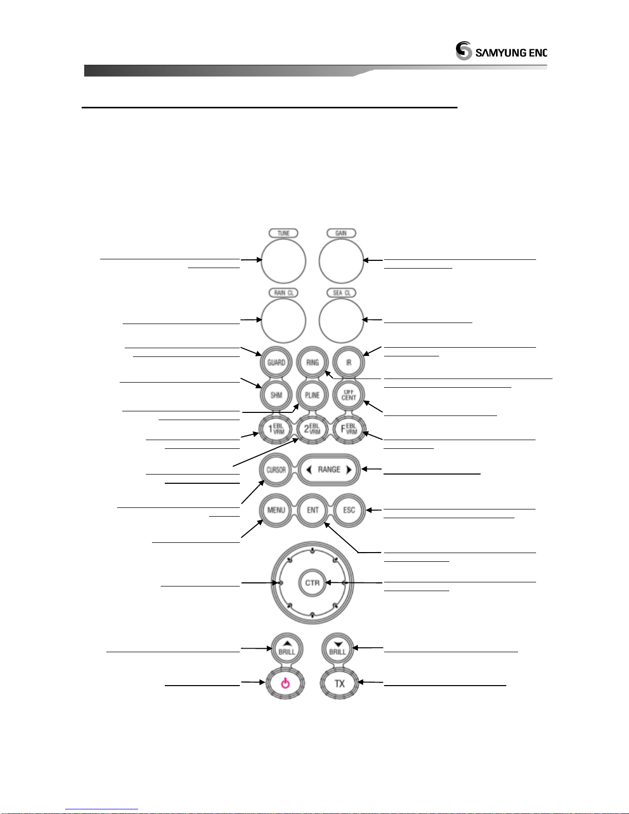
3.1. Front Panel Buttons and Knob ...................................................7
3.1.1. Front Function........................................................7
3.1.2. Directional Key .......................................................8
3.1.3. Display Characters .................................................. 8
3.2. Display Description ................................................................... 8
3.3. Menu Functions ........................................................................ 9
3.3.1. Menu Composition .................................................. 9
3.3.2. MENU Functions ................................................... 11
Chapter 4. How to operate the unit......................................................... 13
4.1. General Idea .......................................................................... 13
4.1.1. Power Input and Operation ................................... 13
4.1.2. Tuning Control...................................................... 13
4.1.3. Image Control ...................................................... 13
4.1.4. Power Off............................................................. 13
4.2. Stand-by for Processing .......................................................... 13
4.2.1. Brightness Change................................................ 13
4.2.2. Language Selection............................................... 13
4.3 Basic Operation ....................................................................... 13
4.3.1. TX ....................................................................... 13
4.3.2. TX Stop................................................................ 13
4.3.3. Tuning Control...................................................... 13
4.3.4. Gain Control ......................................................... 14
4.3.5. Rain/Snow Removal .............................................. 14
4.3.6.
To remove the interference of Sea Level Wave caused by the Sea Wave
.. 15
4.3.7. To operate the alert function.................................. 15
4.3.8. To eliminate/display the scale of Range Ring .......... 16
4.3.9. To remove the Radar Interference ......................... 16
4.3.10. To eleminate the Ship’s Heading Line ................... 16
4.3.11. To use the parallel line ........................................ 17
4.3.12. To move the center of own ship ........................... 17
4.3.13.
To measure the distance and bearing to the Target
...... 17
4.3.14. To change distance unit....................................... 18
4.3.15. To change the way of direction symbol................. 18
4.3.16. To change the way of bearing display................... 19
4.3.17. To change the way of displaying bearing ine/cursor19

2
4.3.18. To compensate the magnetic ............................... 20
4.3.19. To measure the time to the target........................ 20
4.3.20. To display the Waypoint ...................................... 20
4.3.21. To display the other ship’s track line..................... 20
4.3.22
. To make intermittant transmittion for suppressing electric power of Radar.
.... 21
4.3.23. To display ECHO image long on PPI screen........... 21
4.3.24.
To change the color of PPI screen and ECHO image
..... 21
4.4. Other convenient function ....................................................... 22
4.4.1. Display own ship’s speed on the indicator............... 22
4.4.2. To display Ship’s heading on the indicator .............. 22
4.5. Connection to the external navigation equipment ..................... 22
Chapter 5. Screen view............................................................................ 23
5.1. The distance from the target to the height of target ................. 23
5.2. Reflection from the target ....................................................... 23
5.3. Wave Path ............................................................................. 24
5.3.1. Reflection of sea level ........................................... 24
5.3.2. False Image ......................................................... 24
Chapter 6. Installation ............................................................................ 25
6.1. Overview ............................................................................... 25
6.2. Installation of Antenna............................................................ 25
6.2.1. Selection of the installation place........................... 25
6.2.2. How to install Antenna.......................................... 25
6.2.3. Connection to Equipment cable ............................. 26
6.3. DISPLAY SET-UP..................................................................... 27
6.3.1. Location for installation ......................................... 27
6.3.2. How to Install....................................................... 27
6.3.3. Power Cable connection ........................................ 27
6.4. Installation check ................................................................... 27
6.5. Operation check ..................................................................... 27
6.6. Initial Installation ................................................................... 27
6.6.1. Initial Installation.................................................. 27
6.6.2. TUNE-R SET (Tuning Set)...................................... 28
6.6.3. TUNE SET (Tune Level Set) ................................... 29
6.6.4. BEARING ADJUST (Bearing Set) ............................ 30
6.6.5. DISPLAY TIMING (0 Mile Set) ................................ 31
6.6.6. GAIN-L SET (GAIN SET)........................................ 32
6.6.7. STC-H SET (Sea Clutter Set) .................................. 33
6.6.8. MBS SET .............................................................. 34
Chapter 7. Maintenance .......................................................................... 35
7.1. General Maintenance .............................................................. 35
7.1.1. Cleaning............................................................... 35
7.1.2. Chect out the tightness of screw, bolt .................... 35
7.1.3. Check the cabling ................................................. 35
7.2. Scanner ................................................................................. 35
7.2.1. Radom ................................................................. 35
7.2.2. Bracket ................................................................ 35
7.3. Display................................................................................... 35
7.3.1. Cleaning of a Display Screen.................................. 35
Chapter 8. Packing List............................................................................ 36
Chapter 9. Installation drawing and circuit diagram .............................. 38

3
Chapter 1. Overview
1.1. Equipment
SMR-3700 type radar is a small-sized raster scanning
Radar, which composes Radom type transceiver with
4 KW Transmitting power and 10.4 inch color TFT
LCD monitor. Completely sealed case offers one-step
higher stability, and it is designed to protect from
damaging out of heat, salt water and heavy impact.
In addition, it adopts color LCD monitor that can offer
faster recognition of all the floating information on
screen.
1.2. Features
1.2.1. Scanner
It emits the miscrowave toward targets by 4(four)-
step pulse widths according to the radar scale and
transfers the image signals to the monitor that are
made by converting the reflected signals to 2(two)-
step receiver band.
(1) Transmission Output : 4KW
(2) Max. Range : 36NM
1.2.2. Display Unit
SMR-3700 monitor is designed to receive the input
signal from Scanner and displays the optimum
conditions on the TFT LCD screen, based on the
SAMYUNG’s best digital signaling technology.
(1) 10.4 “ color TFT LCD, High Resolution of 640 X
480
(2) One-touch keys dedicated to every function
(3) 10 (ten)-step LCD brightness adjustments
(4) The input of the external navigational devices
such as Gyro or NMEA 0183 enables it to display the
own ship position and the destination
(5) Fixing bracket for the unit
1.3. Composition
(1) Composition and Power Supply
MODEL
SCANNER
UNIT
DISPLAY
UNIT
POWER
SUPPLY
SMR-3700
RSU-3700
SMR-3700
DC 10V ~ 36V
The models are named in English as follows.
(2) Accessories
DESCRIPTION
Qt’
SAMYUNG
CODE
REMARKS
MANUAL
1
SMR-3700-ME
SCANNER-
DISPLAY CABLE
1
RSU-3700-15M
15m
POWER CABLE
1
ACC-CAB-010
3m
SURGE CABLE
1
STR-595
3m
1.4. Construction
4-M10
590
COLOR : WHITE, MASS : APPROX. 10Kg, UNIT : mm
<Drawing 1.1> External Diagram of
RSU-3700 SCANNER

4
COLOR : DARK-GRAY, MASS : APPROX. 5.8Kg, UNIT : mm
<Drawing 1.2> External Diagram of SMR-3700 DISPLAY
1.5. Specifications
1.5.1. General
(1) Display Type : Raster Scan Type
(2) Display Screen :10.4” Color TFT LCD,
Vertical Display
(3) Display Color : GREEN, YELLOW, RED,
WHITE, COLOUR
(4) Display Range : 0.125, 0.25, 0.5, 0.75,
1.5, 3, 6, 12, 24, 36 NM
(5) Distance Resolution : Within 30m
(6) Min. Detection Range : Within 25m
(7) Bearing Accuracy : Within ± 1°
(8) Bearing Resolution : 4.2°
(9) Bearing Input : True Bearing
/ Magnetic Bearing
(10) Environmental Condition
a) Temperature
Scanner : -25℃~ +55℃
Display Unit : -15℃~ +55℃
b) Relative Humidity
Scanner : - below 95% on 35℃
Display Unit : - below 95% on 35℃
c) Relative Wind Speed : 51.5m/sec (100 knots)
(11) Power Consumption : 60W
(12) DC Power : DC 10V ~ 36V
(13) Preheating Time : 90 Secs.
(14) Preaction : Within 3 Secs.
1.5.2. Scanner (RSU-3700)
(1) Dimentions
a) Diameter : 590mm
b) Height : 290mm
(2) Weight : 10Kg
(3) Plane of Polarization : Horizonal Target Wave
(4) Polar Pattern
a) Horizontal Beam Width: 4.0°
b) Vertical Beam Width : 25°
c) Side Lobe Level : Below -21dB
(5) Revolution : Approx. 24 R/Min.
(6) TX Frequency : 9410± 30MHZ
(7) Emission Type: P0N
(8) Peal Power: 4KW
(9) Transmission Bulb : Magnetron JRC MAF1421BY
(10) Transmission Pulse Width/Repetition Frequency
a) Pulse Width Setup : Short
0.08 sec/1640Hz : 0.125, 0.25, 0.5,
0.75,1.5NM RANGE
0.25 sec/1160Hz : 3NM RANGE
0.5 sec/580Hz : 6NM RANGE
1 sec/580Hz : 12, 24, 36NM RANGE
b) Pulse Width Setup : Long
0.08 sec/1640Hz : 0.125, 0.25, 0.5,
0.75NM RANGE
0.25 sec/1160Hz : 1.5NM RANGE
0.5 sec/580Hz : 3NM RANGE
1 sec/580Hz : 6, 12, 24, 36NM RANGE

5
1.5.3. Display Unit (SMR-3700)
(1) Dimensions
a) Width : 290mm
b) Height : 300mm
c) Depth : 142mm
(2) Construction : Desk Type
(3) Weight : 5.8kg
(4) Display Screen : 10.4” Color TFT LCD
(5) Scale Zoom-In : Less than the bigger
one - 1% of used range or 70m
(6) VRM : 000 ~ 64.0 NM –Digital
Display
(7) EBL : 000° ~ 359° - Digital
Display
(8) Sync. Type : Manual/Automatic
Switchable
(9) Bearing Scale : 1° scale, 360°
(10) Bearing Display : Electronic Type
(11) Front Panel
a) Tune : Knob
b) Gain : Knob
c) Rain/Snow Removal : Knob
d) Sea Cluter Removal : Knob
e) Guard : Switch
f) Distance Circle : Switch
g) Interference Rejection: Switch
h) Heading Line : Switch
i) Parallel Line : Switch
j) Center Movement : Switch
k) 1 EBL/VRM : Switch
l) 2 EBL/VRM : Switch
m) F EBL/VRM : Switch
n) Cursor : Switch
o) Range : Switch
p) ESC : Switch
q) Menu : Switch
r) Enter : Switch
s) Center : Switch
t) Directional Button (8 Directions) : Switch
u) Brightness : Switch
v) Power : Switch
w) Transmission : Switch
(12) Menu Type : POP-UP Type
1.5.4. Connection Cable
(1) SCANNER Cable Length : 15m
(2) Power Cable Length : 3m
(3) Max. Data Cable Length : 3m

6
Chapter 2. How it works
2.1. What is Radar ?
Radar stands for Radio Detection And Ranging.
Radar was developed its principles while World War
II, However It wasn’t invented as echo of
navigation equipment.
2.2. Measuring of ownship
position before Radar being
invented.
Before Radar came, vessel is sailing along the
coastline when fogy day, they’re making noise by
ringing the bell or whistle, fire-arrow etc…
A transmitter emits radio waves, which are reflected
by the target and detected by a receiver, typically in
the same location as the transmitter. This enables a
radar to detect objects at ranges where other
emissions, such as sound or visible light, would be
too weak to detect
2.3. Measurement of Radar
Measurement of Radar is mearued by calculating
of time difference between transmitting signal and
reflected echo.
Radar Frequency speed is recognized that its speed
moves 162.000nm per sec regularly.
Thus, it requires the time to check range of signal
reflected as echo from obstacle & signal transmitted
to obstacle. The echo is entirely coming and going,
it needs to be measured only straightline from
obstacle, which should be 1/2 time.
This radar is calculated automatically.
2.4. Measurement of a Course
One way to measure the distance to an object is
to transmit a short pulse of radio signal
(electromagnetic radiation), and measure the time
it takes for the reflection to return. The distance is
one-half the product of round trip time (because
the signal has to travel to the target and then back
to the receiver) and the speed of the signal.
2.5. Speed of Radar waves &
Antenna rotation
The radar waves to obstacle and returning as
echo should be compared from antenna speed very
quickly.
Then, the first transmitting of very short radar
pulse is returning as echo at the same time its
scanner rotating.
2.6. Radar Display
As it called PPI(Plan Position Indicator), which is
displayed in distance & course from obstacle.
This display is indicated as reverse image being
transmitting ownship position in the middle.
Its course, distance are displayed as echo image
from center of PPI.
Continuous obstacle image is displayed, also
moving of vessel which is transmitting.
Ownship(Radar)
< Sample : Real Radar >
Obsatacle
PPI
Range of
Obstacle related
to ownship.
Heading Line
Ownship position in the middle.
< Sample Radar Screen >

7
Chapter 3. How to operate panel and menu
3.1. Front Panel Buttons and Knob
It is available to display and adjust the various data on the screen by using the the control keys as follows;
(1) Dedicated 4 (Four) Volumes
(2) Directional key for 8 (Eight) directions and center key for moving to the display center
(3) Dedicated 19 (Nineteen) keys
(4) Available to select every function in Menu
3.1.1. Front Function
<Drawing 3-1> Front Knob & othe Fron Button
To indicate the circle for the reference
of the distance measurement.
To decide the set value or select
the menu item.
To decide the set value or select
the menu item.
To dark LCD display brightness.
Stand By and TX conversion.
To call Menu display.
Directional button.
To light LCD display brightness.
To turn ON / OFF.
To remove any interference to
other radars.
To adjust snow, rain clutter.
To adjust the guard of the
receiving signal.
To adjust sea clutter.
To adjust the guard frequency of
the receiver.
To set up the monitor zone
and alarm on the screen.
To move the image center.
To indicate the heading line
& the parallrel line.
To indicate the heading line.
To set up and indicate the flexible
EBL & VRM.
To set up and indicate
NO.1 EBL & VRM.
To set up and indicate
NO.2 EBL & VRM.
To indicate the cursor on the
screen.
To adjust the distance.
To return to the previous screen or
escape to the previous display.

8
3.1.2. Directional Key
Tey are used to move the cursor, turn the EBL, change the VRM size and move to any of the sub-menu. They
are used to operate the following functions.
How to operate the exclusive keys
GUARD
CURSOR
OFF
CENT
EBL
VRM
1
EBL
VRM
2
EBL
VRM
F
MENU
P.LINE
3.1.3. Display Characters
Descptions
Position
Display
Characters
Guard
Right Top
G
Interferance
Right Top
IR
EBL/VRM
Left Bottom
1 2 F
Cursor
Right Bottom
CSR
Wake Point
Right Top
W
Target Extention
Right Top
EXT
Auto Tune
Left Top
A
3.2. Display Description
KM
1
2
3
4
5
6
7
8
9
10
11
12
13
14
15
16
17
18
19
20
21
22 23 24
25 26 27 28
KM KM
KM
(1) : Extension
(2) : Wake
(3) : Interference Rejection
(4) : Guard Setup
(5) Parallel Line
(6) Heading Line
(7) 1 EBL
(8) Cursor Position Bearing /
Distance / Arrival Time
(9) Display Color
(10) Indication of the set
EBL/VRM bearing & distance
(11) 1 EBL/VRM
(12) 2 EBL/VRM
(13) F EBL/VRM
(14) 2 EBL
(15) 2 VRM
(16) 1 VRM
(17) Cursor
(18) Guard Zone
(19) Distance & Bearing between
Parallel Lines
(20) Tuning Bar
(21) Range
(22) Distance between range ring
(23) Auto Tuning
(24) Heading Bearing
(25) Speed
(26) Heading Display
(27) Latitude
(28) Longitude
The bearing, speed, latitude, longitude on the top of the screen and the destination setup on the right
bottom of the screen are displayed only when the signal from Gyro and GPS is input data port.
To set up the alarm zone
To set up the distance & bearing
between parallel lines
To set up the center movement point
To move the cursor
To set up EBL/VRM
To move to the sub-menu
To change the adjustment value in
the initial setup menu

9
3.3. Menu Functions
In addition to the functions used by the front panel keys, SMR-3700 has the functions to enable user to
control with menu.
3.3.1. Menu Composition
It is available to converse the display language to Korean, English. Russian, Chiness.
For the conversion of the display language, please refer to ‘4.2.2 How to converse the language’.
(1) Press button by using to select any wishful setup menu.

10
(2) Initial Setup Menu for installer
At INIT. SET of ‘MENU’, press button, the following display will appear.
For any additional item, please refer to ‘6.6 Initial Setup by Installer’.
Initial Setup
by Installer
Additional Item

11
3.3.2. MENU Functions
To use the functions attached with ‘※’, it is required to get connected with external navigational device.
FUNC/DISPLAY
SET
※BEARING : To select the display of PPI image
bearing.
※EBL/CSR READ OUT : To decide whether the
bearing and the cursor are to be displayed
‘Relative’or ‘True’.
※Megnetic Correction : To adjust the magnetic
correction value.
DISTANCE UNIT : To select the unit of the
distance measured by VRM or Cursor.
NM : Nautical Mile
KM : Kilometer caculated from NM
KM-River: Display a distance unit for River
WAKES : To indicate the track of the moving
target according to the time intervals.
Short : 5 Circles, Long : 10 Circles
※WAYPONT : To display the position of the
target on the screen.
※HEADING MODE : To select the display of the
own ship heading.
RADAR SET-UP
TIMED TX : To decide the automatic repetition
of the TX status and the stand-by for
saving the power.
TX PERIOD : To set up the TX intervals by the
number of the rotations
STAND-BY TIME : To set up the time of the
stand-by status
ALARM LEVEL : To indicate the level of the
image to make an alarm.
Even if the level becomes lower, it is designed
rings by the weak image signal and reacts
sensitively.
TX PULSE : To set up the TX pulse width.
Short : The resolution is good.
Long : The gain is good.
TARGET MAG. : To expand the image size
freely on the screen.
TUNING MODE : To select ‘Automatic’or
‘Manual’.

12
At INIT. SET of ‘MENU’, press
button, the following display will appear.
CAUTION
For the initial setup by installer, users must not make any adjustment to
avoid any vital functional problems as the installer normally adjusts it to
the optimum conditions according to the situation of the ship.
INIT. SET
LANGUAGE SET : To set up the language in
use.
SIMULATION : To show the simulation.
OUTSIDE COLOR : To set up the external
desktop color of the screen.
INSIDE COLOR : To set up the internal desktop
color of the screen.
COLOR SET : To set up PPI image color.
Initial Setup by Installer
DISPLAY TIMING : To adjust the PPI image
distance.
TUNE SET : To adjust the status of the tuning
bar. (Fixed at 060)
TUNE-R SET : To adjust the tuning volume.
ERROR SET : To adjust the error status.
TX-TIME : To indicate the TX time.
GAIN-L SET : To adjust the gain volume.
(Fixed at 000)
BEARING ADJUST : To adjust the PPI image
bearing.
STC-H SET : To adjust the sea clutter volume.
MBS SET : To adjust MBS distance.
PROGRAM LOAD : Function to upgrade
program.
LCD SET : Setting based on LCD version.

13
Chapter 4. How to operate the unit
4.1. General Idea
4.1.1. Power Input and Operation
(1) Power Input
a) To power on, press button.
b) Afte power on, Count Down Timer is displayed
on SAMYUNG Logo screen, it is converted to
the stand-by in 1 min. 30 secs.
c) As the TX time is consolidated and displayed,
user can judge the ideal time for repair.
d) It indicates the version of the program.
(2) TX
a) Press button to enable the transmission
at the stand-by status.
b) Press button again to convert the TX
status to the stand-by status.
4.1.2. Tuning Control
It is required to control the tuning of the unit both
manually and automatically.
The conversion is selectable in the setup of MENU.
For the automatica tuning, “A” is displayed next to
the tuning bar.
(1) Conversion of Tuning Mode
Menu screen
Move to RADAR SET-UP
, Move to TUNING MODE, press
, Move to Auto /Manual, press
Back to PPI screen
(2) Adjustment of Tuning Volume
a) In case of tha manual tuning mode, turn the
volume to adjust the image biggest.
b) Adjust the movement of the tuning bar biggest.
c) In case of the automatic tuning mode, it is
needless to turn the volume.
d) If any image doesn’t appear, adjust the
volume again or turn the volume of
/(rain/snow) removal.
4.1.3. Image Control
a) the volume of the tuning/gain of
(sea clutter), (rain/snow),
removal to display the optimum image.
b) Press button to convert the
processing range of the image.
4.1.4. Power Off
(1) TX stop.
Press button to convert to the stand-by
status.
(2) Turn off the power.
Press and hold on button for 1~2 secs, the
radar operation will stop and all the performances
will stop, too.
4.2. Stand-by for Processing
4.2.1. Brightness Change
a) Press button, the screen will get brighter.
b) press button to have the darker screen.
[ Ref. ] ☞There are 10 (ten) stages adjustable in
the brightness.
4.2.2. Language Selection
Menu screen
Move to INIT. SET
, Move to LANGUAGE SET
, KOR / ENG / RUS / CHI /ITA,
press
Back to PPI screen
4.3 Basic Operation
4.3.1. TX
Press button, it will be converted to TX
from the stand-by status.
4.3.2. TX Stop
Perss button again at the TX, it will be the
stand-by status.
4.3.3. Tuning Control
Please refer to ‘4.1.2, Tuning Control’.

14
4.3.4. Gain Control
(1) How to control Gain Control
Turn to the left to decrease the Gain and to the right to increase the Gain.
(2) To adjust the optimum gain
The echo image size by target is the biggest and any targets nearby do not contact the echo image.
감도가 낮아 영상이 작다. 감도가 최적이다. 감도가 높아 2개의
영상이 붙었다.
4.3.5. Rain/Snow Removal
(1) If much rain/snow, it is difficult to analyze the wishful target image as the echo by rain/snow clutter
appears on the PPI display.
(2) Turn (rain/snow) to the right to remove the echo image by snow and rain.
Reflected Wave of Rain/Snow Removed Rain/Snow
(Target Retricted, too)
ATTENTION
※It should be always observed by adjusting the optimum conditions.
※If the gain is too low, the targets may not be displayed.
※If too high, it may be an obstacle in observation due to the noise increase on the
PPI display.
ATTENTION
※Too much adjustment of rain/snow removal will restrain the target of ships or
hazards as well as any images by rain/snow. This can be the cause of image
analysis.
※In case of use of rain/snow removal, the optimum conditions should always set up.
Small Imge by Low Gain
Optimum Gain
2- images contact
by high gain

15
4.3.6. To remove the interference of Sea Level Wave caused by the Sea Wave
(1) When the wave becomes high due to heavy wind, the ECHO(Sea Clutter) due to the wave is displayed on
PPI screen, then it will be difficult to detect the image of the target.
(2) Turn (Sea Clutter) to the right to remove the echo image by wave.
The status that shows Sea Level Relection The status that shows Sea Level Reflection is
is strong due to Wave. being suppressed. (The Target is also suppressed)
4.3.7. To operate the alert function
Set the guide zone in order to use the alert.
Guard Zone means [Zone] to be set on PPI screen.
(1) Guard Zone Setting
In bottom of the screen, the function
of GUARD:RingFan is shown and
in bottom-right of the screen, CRS
Data is shown with the distance &
bearing of the cursor based on the
position of own ship.
Press to select Ring or Fan
function.
a) How to set up Alert Zone based on the position
of own ship as selecting Ring function.
The message of Press ENT to set
is shown onto a screen with a red-
ring mark.
Adjust the Alert Zone controlling the
rea-ring.
The alert zone is set up and the
sound is ringing, if it has a target in
the zone.
b) By selecting Fan function, how to set up a
specific zone onto a heading of PPI screen.
Put the cursor onto top-left in a
specific zone to be controlled by
using a bearing button.
Press ENT to set is shown in a
screen.
Move the cursor to bottom-right in a
specific zone to mark the fanning-
shape.
The alert zone is set up and the
sound is ringing, if it has a target in
the zone.
ATTENTION
※If you set the removal function of Sea Level Wave up to removal of all Sea Level
Reflection at short distance, it causes intereference in detecting images due to the
target of vessel and dangerous things as well as the wave images being
suppressed.
※When you use the removal function of Sea Level Wave, you make sure it should be
the optimistic set of suppression.

16
(2) Change of the alert level
Menu screen
Move to RADAR SET-UP
, Move to ALARM LEVEL, press
, Move to 1/ 2/ 3/ 4/ 5/ 6/ 7,
press
Back to PPI screen
[ Ref. ] ☞Alarm level 1 ~ 7 represents Image
Level (ECHO Level) sounding the alert.
1Being selected, it gives the alert sound to all
images shown in Screen.
7Being selected, it gives the alert sound to the
strongest image displayed in the screen.
(3) Occurrence and Stoppage of the alert
sound
a) When pressed the button, the alert sound
is stopped.
b) If you press the button again, alert sound
is coming.
(4) Termination of the alert
When button is pressed, all alerted status is
terminated.
4.3.8. To eliminate/display the scale
of Range Ring
(1) Press button three times.
The brightness of Range Ring is adjusted in 3
steps.
4.3.9. To remove the Radar
Interference
ATTENTION
※When using the function of Intereference
Removal, weak image such as a dangerous
thing may happen to be removed.
※Stop the function of interference removal
when you see Radar BEACON an SART signal.
Radar Interferene means Micowave transmited by
other ship’s Radar is displayed on PPI screen, which
is directly affecting to own ship’s Radar air line.
(1) Whenever pressing button, it marks with
IR-1, IR-2, IR-3 in order in the top-right screen.
(2) IR-3 is the status that shows Radar
interference a lot. (IR=INT REJECT)
<Before Interference Removal>
IR-1
<lAter Interference Removal>
4.3.10. To eleminate the Ship’s
Heading Line
(1) Press button.
a) Ship’s Heading Line is indicating own ship’s
heading direction.
b) When you are pressing button
continuousely, ship’s Heading Line is off and it
is displayed again when you hand the key off.
Inteeference Removal Function
Radar interefence

17
4.3.11. To use the parallel line
Length-parallel line for distance and
width-paralled line for bearing are
shown as one line at PPI screen and
the bearing & distance for the
between paralled lines are marked in
the top-left of the screen.
button can adjust the parallel lines
bearing.
button can adjust the distance of the
parallel line.
4.3.12. To move the center of own
ship
It can use for securing the wider sight to the
specific direction from the center of own ship.
Shows “+”cursor in a center of PPI
screen.
Move the cursor to a desirable
position.
The center of own ship moves to the
position of the cursor.
Return to the original position.
[ Ref. ] ☞To the foreward and afterward direction,
80% of screen can be moved while 60% of screen
can be moved to the reft and right side.
4.3.13. To measure the distance and
bearing to the Target
a) Use button.
EBL means Electronic Bearing Line.
VRM means Variable Range Maker.
b) Use button.
c) Use button.
(1) How to measure the distance & bearing
for targets by using EBL/VRM function
VRM & EBL are shown from the
center of the PPI screen.
Values for bearing & distance are
shown at the bottom-left of the
screen.
Able to adjust EBL.
Able to adjust VRM.
Function is end.
(2) Press button.
The method of adjustment is same as
‘1 EBL/VRM’.
(3) How to measure bearing & distance from
a target to target by using F EBL/VRM
function.
VRM & EBL are shown at the top-
right of the PPI screen.
Shows Press ENT to set on a
screen and a cursor and values for
distance & bearing are shown at the
bottom-left of the screen. CRS Data
is shown with the distance & bearing
of the cursor based on the position
of own ship.
Move the cursor to a desirable
position.
EBL & VRM is moved.
Function is end.
(4) The purpose to use ‘1 EBL/VRM’,
‘2 EBL/VRM’functions both
a) Two different colored EBL and VRM appears on
the Screen.
b) Use for measuring distance/ bearing for more
than one target.
c) It displays Function key which is currently
using at 1 2 F on the left bottom of screen.
d) For termination, you may press the currently
using function key once more.
[ Ref. ] ☞‘1 EBL/VRM’, ‘2 EBL/VRM’in case of
using the functions both, in case of using ‘F
EBL/VRM’function , ‘2 EBL/VRM’function is
disappeared and ‘1 EBL/VRM’&‘F EBL/VRM’
functions can be available.
(5) How to measure the distance & bearing
for targets by cursor funtion.
Distance/Bearing value along with
CSR display appears on the right
bottom of screen.
Cursor / Data is disappeard.
(6) Press Parallel line key.
Please refer to how to use ‘4.3.11. To use the
parallel line’.

18
4.3.14. To change distance unit
Menu screen
Move to FUNC/DISPLAY SET
, Move to DISTANCE UNIT,
press
,
Move to NM / KM / KM-River,
press
Back to PPI screen
(1) NM(Mile, Nautical Mile)
Cusor, VRM, Distance of Parallel Line represents
NM
.
(2) KM(Killo Meter)
Cursor, VRM, Distance of Parallel Line represents
KM
.
(3) KM-River(For river vessels)
Radar for river vessel represents Range.
4.3.15. To change the way of
direction symbol
Menu screen
Move to FUNC/DISPLAY SET
, Move to HEADING MODE,
press
, Move to H-UP/N-UP/C-UP,
press
Back to PPI screen
(1) HEAD-UP
a) Ship’s head is displayed to the HEAD UP (Its
bearing scale is 0) on PPI screen.
b) If ship’s head is changed, ECHO image bearing
on screen is also changed.
c) If you could not obtain bearing reference from
external navigation equipment like GYRO
COMPASS, it sets out with this bearing display.
<PPI image moves counterclockwise.>
(2) NORTH-UP
a) Make the North on the chart indicate the real
North on the screen.
b) Even though the ship’s headline is chaged, the
bearing on the screen would not change.
c) It requires the equipment like GYRO
COMPASS to obtain bearing reference.
<Ship’s headline moves clockwise>
When the own ship
moves clockwise.
When the own ship
moves clockwise.

19
(3) COURSE-UP
a) Make the ship’s head bearing always indicate
Course-up when the course is set.
b) Even though ship’s head direction is changed,
ECHO image bearing does not change but
ship’s head moves as much as the variation of
ship’s head bearing.
c) When you change the track widely, set the
course up again from the MENU.
d) It requires the equipment like GYRO
COMPASS to obtain bearing reference.
<Ship’s head line moves clockwise>
<In case that Course-up is reset>
4.3.16. To change the way of bearing
display
Menu screen
Move to FUNC/DISPLAY SET
, Move to BEARING, press
, Move to True /Magnetic, press
Back to PPI screen
(1) True Bearing
a) True bearing indication is set based on True
North with Scale 0.
b) It requires the equipment like GYRO
COMPASS to obtain bearing reference.
(2) Magnetic Bearing
a) Magnetic Bearing indication is set based on
Magnetic North with Scale 0.
b) MAGNET COMPASS is needed.
4.3.17. To change the way of
displaying bearing ine/cursor
When you display the value of cursor or EBL
bearing, select between the own ship and True
North as a base.
Menu screen
Move to FUNC/DISPLAY SET
, Move to EBL/CSR READ OUT,
press
, Move to Relative / True/Mag. ,
press
Back to PPI screen
(1) ‘Relative’ indication
Make the Cursor, and the Bearing value of EBL
indicate based on Ship’s headline (Ship’s head Line
is “0º”)
(2) True North Indication
Make the cursor, the bearing value of EBL indicate
based on True North.(True North is “0º”)
When the own ship
moves clockwise.

20
4.3.18. To compensate the magnetic
Input the value of compensation because
Magnetic North Bearing is little bit different
according to the Navigation zone.
Menu screen
Move to FUNC/DISPLAY SET
, Move to MAGNETIC VAR.,
press
, Move to Auto / Manual +00.0º,
press
Back to PPI screen
(1) In case of setting ‘Automatic’,
Status of no compensated values.
(2) How to input compensated values by
‘Manual’ set up
Menu screen
Move to FUNC/DISPLAY SET
, Move to MAGNETIC VAR.,
press
, Move to Manual
Press +00.0º button.
Input compensated values by button
The values are set up
Back to PPI screen
[ Ref. ] ☞Adjust Range : - 99.9º ~ + 99.9º
: ± 0.1 Step Adjust
: ± 1.0 Step Adjust
4.3.19. To measure the time to the
target
a) Use the cursor function.
b) In needs the input of own ship’s speed data from
external navigation equipment.
In case of connecting to external
navigational equipments, values ‘bearing,
distance, time, lon/lat’are shown from the
own ship to the cursor in CRS Data of the
bottom-right.
Move the cursor to a target by bearing
button and get the data.
The cursor / data are disappeared in PPI
screen.
4.3.20. To display the Waypoint
To use this function, it needs the input of bearing
data, distance data to go waypoint and own ship’s
speed data on the indicator.
Menu screen
Move to FUNC/DISPLAY SET
, Move to WAYPOINT, press
, Move to On, press
Back to PPI screen
(1) Waypoint set
In case of setting On, values ‘distance, bearing,
lon/lat for waypoint’(Connecting to external
navigational equipments) are shown.
(2) Remove Waypoint
In case of setting Off, the data is disappeard.
4.3.21. To display the other ship’s
track line
a) It can ascertain the other ship’s movement in
track line distance and direction and it facilitates
to avoid collision of the ship.
b) The lomger target track line is displayed, the
faster the other ship’s speed is. The shorter, the
slower.
c) The length of the track line is displayed “Short,
Long”.
Menu screen
Move to FUNC/DISPLAY SET
, Move to WAKES, press
, Off / Short / Long
(Move to Short, press )
Back to PPI screen
(1) Track Line Memory ‘Short’
a) PPI image is added to Screen until 5
revolutions of Antenna comes.
b) The color of moving target track line is
changed by every 5 revolutions passed.
(2) Track Memory ‘Long’
a) PPI image is added until 10 revolutions of
Antenna comes.
b) The color of moving target track line is
changed by every 5 revolutions passed.
Other manuals for SMR-3700
1
Table of contents
Other Samyung Marine Radar manuals