S&B Lawn Systems Lawn Stryper LM-408111B User manual

Visit www.patternyourlawn.com
Owner’s Manual
Read, Understand and Follow ALL Instructions prior to use.
Lea, entienda y siga todas las instrucciones antes de usar.
S&B Lawn Systems, Inc. / W226N825 Eastmound Drive, Suite B
Waukesha, WI 53186-1690 USA / Visit www.patternyourlawn.com
Model No.
LM–408111B
LM–408111R
LM–408111G
Patent Pending
MADE, ASSEMBLED AND PACKAGED IN AMERICA
S&B Lawn Systems, Inc.
W226N825 Eastmound Drive, Suite B
Waukesha, WI 53186-1690 USA
Copyright © 2008 S&B Lawn Systems, Inc.
Printed in the USA

Congratulations...
On your purchase of the Lawn StryperTM, a S&B Lawn Systems, Inc.
product. The Lawn StryperTM attachment is designed to easily and safely attach
to most walk-behind, self-propelled and push-type lawn mowers. When used
properly, the Lawn StryperTM attachment will allow you to pattern your lawn just
like the pros do at golf courses, landscape firms and major league ballparks.
Prior to creating an eye-popping, people stopping lawn of art with the
Lawn StryperTM attachment, make certain to read and understand all of the
instructions in this Owner’s Manual. You are responsible for proper product
use and safety.
For great Lawn StryperTM patterns, grass tips, product registration, contact
information and more visit www.patternyourlawn.com.
S&B Lawn Systems, Inc. thanks you for your purchase and we wish you and
your patterned lawn much happiness for years to come.
Chance to WIN $1,000.00 Gift Card!!!
Get a chance to WIN a $1,000.00 gift card to your favorite
Home and Garden store by sending us your ‘before and
after’ lawn pictures while using the Lawn StryperTM
attachment. Visit www.patternyourlawn.com for details.
Certain rules and regulations apply, see contest rules on website for details.
2 3
•
•
•
•
•
•
•
•
•
•
Safety:
Read, and understand all of the instructions in this manual prior to
using the Lawn StryperTM attachment. Follow those instructions
whenever using the Lawn StryperTM attachment.
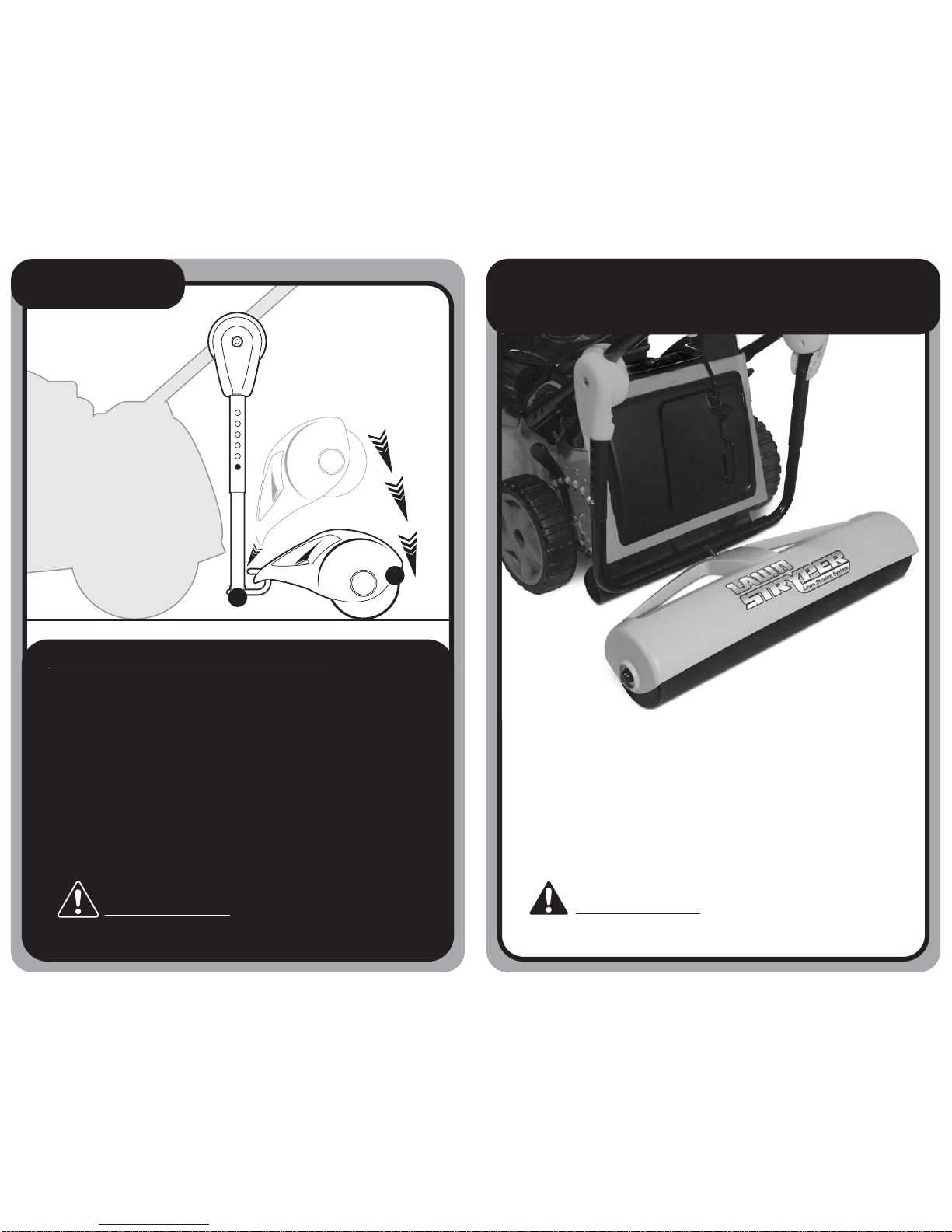
Lawn StryperTM attaches to and follows behind your lawn mower during
normal grass-cutting operations, and should not affect the operating
characteristics of your mower. Carefully follow all of your lawn mower
manufacturer’s operating instructions and warnings when using the
Lawn StryperTM attachment.
Lawn StryperTM attachment should not interfere with normal mower
operations, such as cutting / mulching / bagging. If there is any
interference IMMEDIATELY SHUT OFF MOWER, then inspect the
Lawn StryperTM attachment installation, make any adjustments needed
to correct the problem, and reassess operations to verify that the
interference has been resolved.
The Lawn StryperTM attachment is designed to work with most
walk-behind, self-propelled and push-type lawn mowers.
DO NOT USE WITH ANY OTHER TYPE OF MOWER.
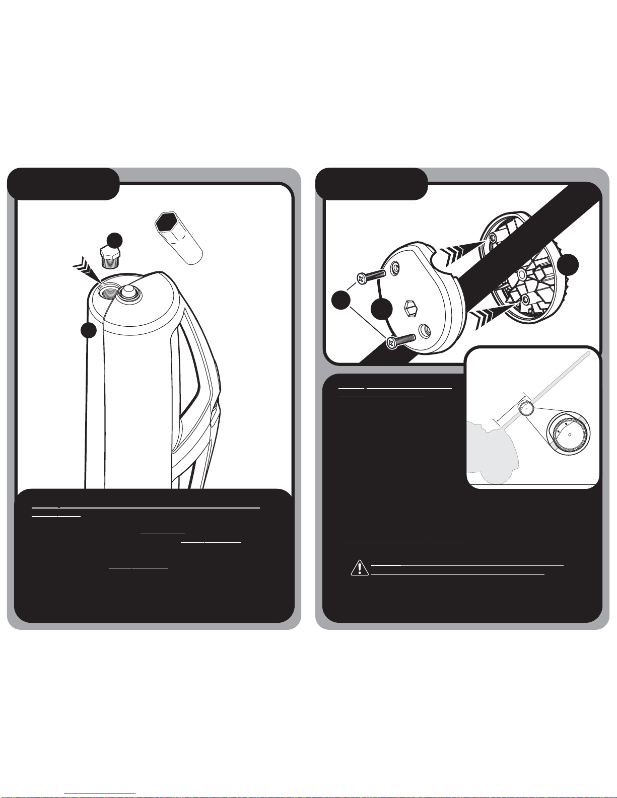
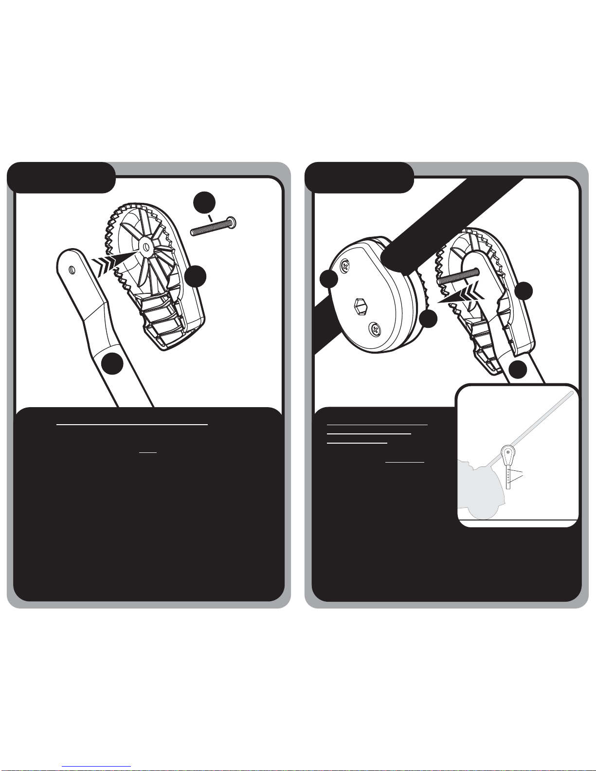
The Lawn StryperTM attachment must be properly installed, attached,
and adjusted in order to work along with your particular lawn mower.
Do not assemble, disassemble, attach, inspect, or adjust the
Lawn StryperTM attachment while the mower is running.
SHUT OFF THE MOWER before performing any of these actions.
Never stand on the Lawn StryperTM attachment, roller assembly,
cover, or clamps.
Keep hands and feet clear of the Lawn StryperTM attachment during
mowing operations.
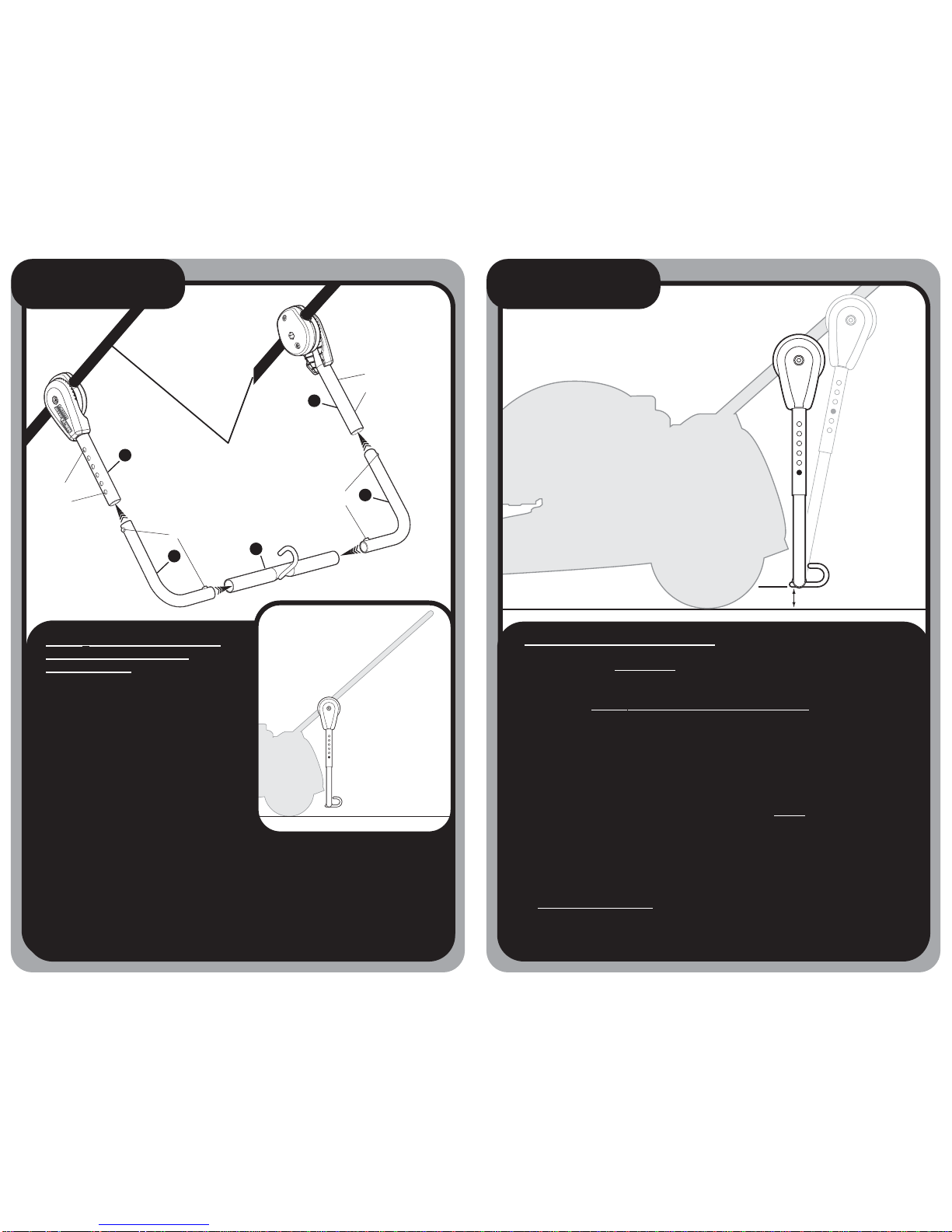
Install the Lawn StryperTM attachment on your mower so that it does
not interfere with your ability to walk behind the mower.
If the Lawn StryperTM attachment should interfere with your ability to
mow around obstructions, walkways, or other tightly constrained areas,
SHUT OFF THE MOWER, remove the roller assembly, and then mow
around the obstructed area without the roller assembly attached (but
with clamp and tube assembly still in place). Once this is completed,
once again SHUT OFF THE MOWER, replace the roller assembly,
and then continue with the rest of your patterned mowing.
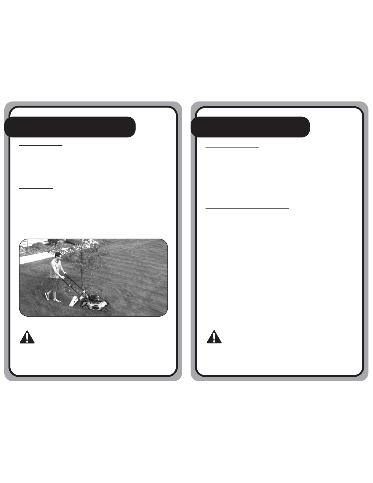
tBefore tAfter

Parts:
A. (2) BSI-LNS-011 Lawn StryperTM Inner Clamp(s)
B. (2) BSI-LNS-012 Lawn StryperTM Outer Clamp(s)
C. (2) BSI-LNS-015 Lawn StryperTM Angle Adjuster(s)
D. (1) BSI-LNS-003 Lawn StryperTM Hitch Tube
E. (2) BSI-LNS-017 Lawn StryperTM Corner Tube(s)
F. (2) BSI-LNS-013 Lawn StryperTM Vertical Tube(s)
G. (1) BSI-LNS-022 Lawn StryperTM Roller Assembly
H. (1) BSI-LNS-021 Lawn StryperTM Roller Plug
I. (2) 2" Inch Phillips Pan Head Screw(s)
J. (2) Hex Nut(s) – ALREADY ASSEMBLED in Inner
Handle Clamp(s), (A)
K. (4) M5x20 Phillips Oval Head Screw(s)
B
B
A
A
C
C
D
F
F
E
E
I
I
G
H
K
J
Lawn StryperTM Parts View
54
DO NOT place clamp system over any type of existing wires/
cables that may be present on lawn mower handlebars.
Assembly:
• TOOL Required: Phillips Screw Driver.
• Roller fills with approx. 16 to 20 lbs. of DRY sand.
(sand not included)
IMPORTANT: Work on a flat level surface – make
certain mower is NOT running.
CAUTION: Do not assemble, disassemble, attach, inspect, or
adjust the Lawn StryperTM attachment while the mower is running.
SHUT OFF THE MOWER before performing any of these actions.

G
Pour DRY sand
into opening.
H
Step 1
Step 1: Fill Roller Assembly With Approximately 16 to 20 lbs.
of DRY Sand.
Completely fill Roller Tube (G), WITH SAND, via hole located on end
of tube. Once completely filled, thread and FULLY TIGHTEN Roller
Plug with provided Roller Plug Fastener.
User Tip! Failure to FULLY TIGHTEN roller plug will result in the
Roller Plug blocking the roller’s ability to turn. Failure to fill roller
with recommended amount of sand may result in a less dramatic
patterning effect.
B
A
Lawn Mower Handlebar
K
Step 2
Step 2: Attach Inner and Outer
Clamps to Handlebars.
Within the LOWER THIRD of lawn
mower’s handlebar, place Inner
Clamp (A) on inside of handlebar
while attaching Outer Clamp (B)
on outside of handlebar. Connect
Inner Clamp (A) and Outer Clamp
(B) as outlined in above diagram.
Outer Clamp’s teeth (B) should be
facing outward. Check that the
word (KUPK), located on Outer
Clamp (B) is facing upward.
REPEAT same process on other handlebar. Make certain Outer Clamp’s
teeth (B) are facing outward. Check that the word (KUPK), located on
Outer Clamp (B) is facing upward.
INSERT AND PARTIALLY TIGHTEN M5x20 Oval Head Screws (K) as
outlined in above diagram.
User Tip! Line up the extended square inserts on Outer Clamp (B) for
easy attachment to Inner Clamp (A).
1/3 Distance
UP
56 7
DO NOT place clamp system over any type of existing wires/
cables that may be present on lawn mower handlebars.
This diagram shows the RIGHT-HAND
handlebar of the lawn mower.
Roller Plug Fastener
e
UP

F
C
I
Step 3
Step 3: Insert Vertical Tubes into Angle Adjusters.
Set Vertical Tube (F) into Angle Adjuster (C). Make certain that top
portion of Vertical Tube (F) rests FLATon inner portion of Angle Adjuster
(C) as outlined in above diagram. Screw holes should match up.
Insert 2" Pan Head Screw (I) as outlined in above diagram.
Repeat process for other Vertical Tube.
Lawn Mower Handlebar
C
F
A
B
Step 4
Step 4: Attach Angle Adjuster
Assembly to Handlebar
Clamp Assembly.
Align, attach and PARTIALLY
tighten Angle Adjuster assembly
to Handlebar Clamp assembly as
outlined in above diagram.
Repeat process on other handlebar.
User Tip! Do not fully tighten at
this point. Angle adjustments will be made in later steps. Double check
that Valco Holes, on Vertical Tubes (F), are facing outward and that the
Lawn StryperTM logo, on Angle Adjuster assembly, is facing outward.
89
Valco Holes
This manual suits for next models
3
Table of contents