Sandbender Technology 1PICA0001 User manual

Document Number
IEMAN000001
Document Revision
R003
Page
1 of 22
Document Title
CAN Interface pHAT User Manual
Document Legal Notice/License use
Document Release Status
Released
Document Type
User Manual
CAN Interface pHAT
User Manual
Document Number: IEMAN000001
Document Revision: R003
For Product SKU: 1PICA0001
Copyright © 2018 Sandbender Technology Ltd,
8 Coronation Grove, Harrogate,
North Yorkshire, HG2 8BU.

Document Number
IEMAN000001
Document Revision
R003
Page
2 of 22
Document Title
CAN Interface pHAT User Manual
01/06/2018 2 of 22
Contents
1 Introduction...................................................................................................................... 3
1.1
What is the purpose of this document ........................................................................................... 3
1.2
Who should read this document.................................................................................................... 3
1.3
How is this document organised ................................................................................................... 3
1.4
How do you receive more information........................................................................................... 4
1.5
Document Revision history............................................................................................................ 4
1.6
Supporting documents................................................................................................................... 4
1.6.1
External publications............................................................................................................. 4
1.7
Trademarks ................................................................................................................................... 4
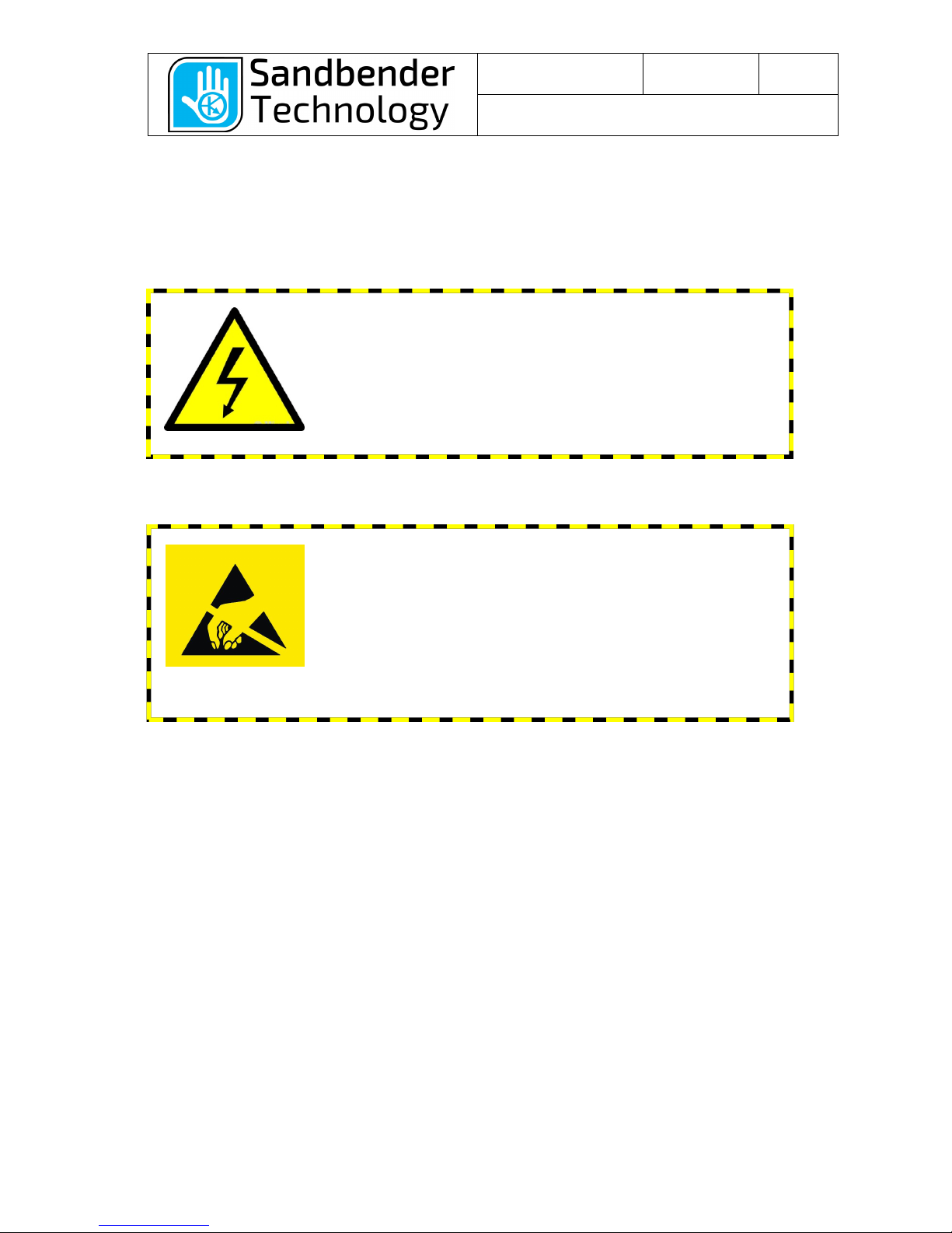
2 Hazards, Warnings and Conformance............................................................................ 5
2.1
Hazardous Voltages ...................................................................................................................... 5
2.2
ESD Precautions ........................................................................................................................... 5
2.3
RoHS ............................................................................................................................................. 5
2.4
CE Marking.................................................................................................................................... 5
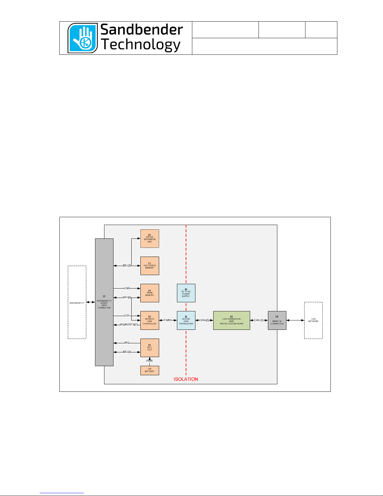
3 Functional Description .................................................................................................... 6
3.1
Overview........................................................................................................................................ 6
3.2
Functional Groups ......................................................................................................................... 7
3.2.1
HAT 40 WAY GPIO CONNECTOR ...................................................................................... 7
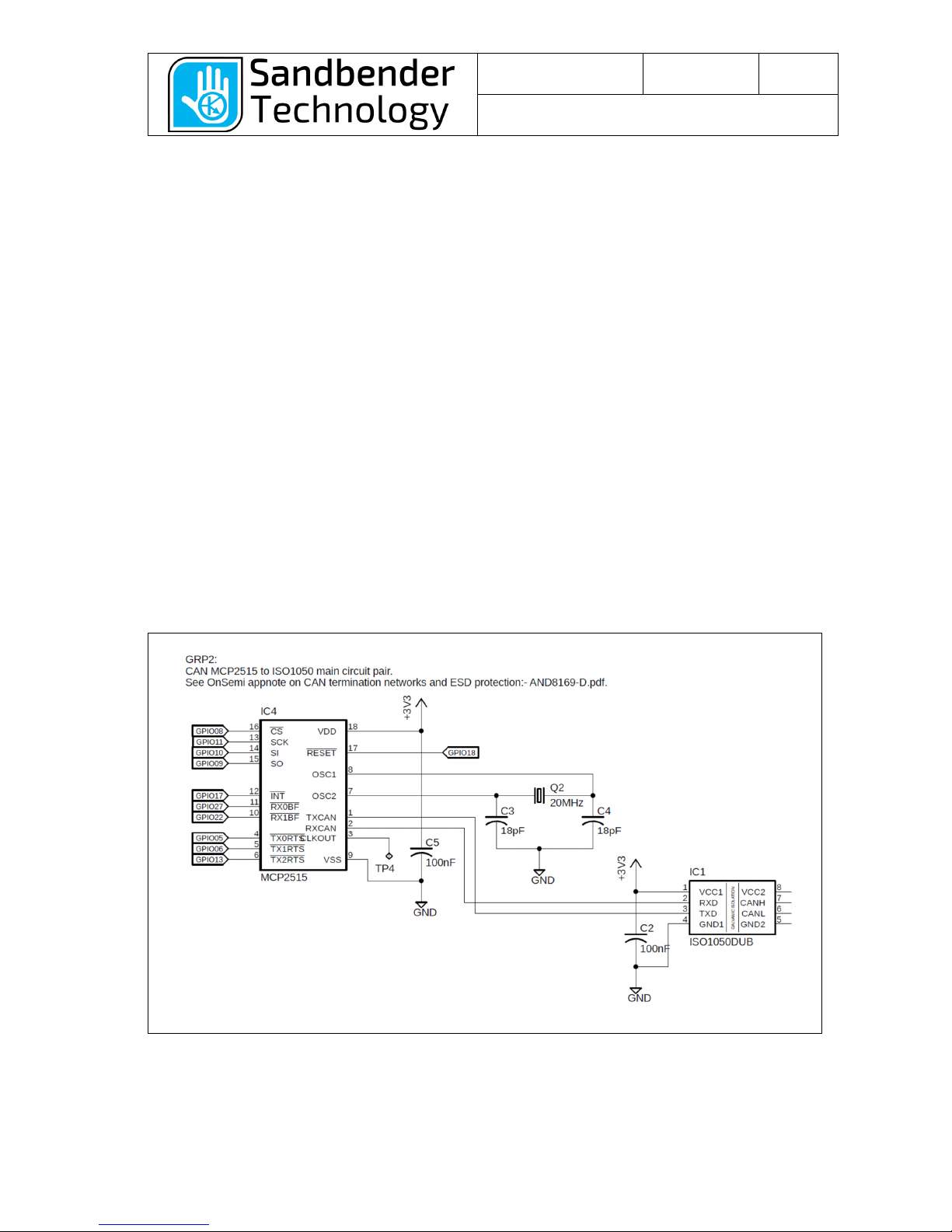
3.2.2
CAN Controller and Transceiver........................................................................................... 8
3.2.3
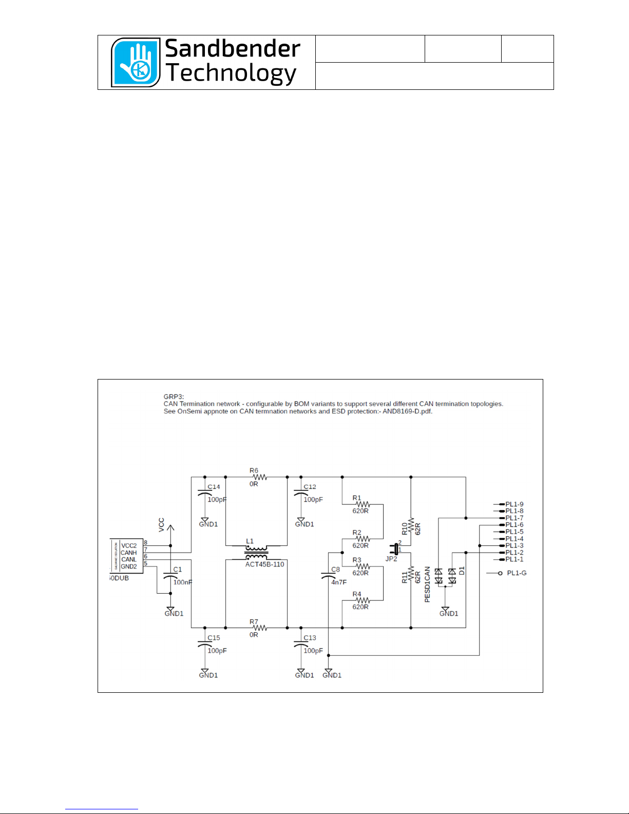
CAN Termination and Connector........................................................................................ 10
3.2.4
FRAM EEPROM ................................................................................................................. 11
3.2.5
RTC and Battery ................................................................................................................. 12
3.2.6
DC to DC Converter............................................................................................................ 13
3.2.7
HAT Configuration EEPROM.............................................................................................. 14
3.2.8
Grove Connector ................................................................................................................ 15
3.2.9
Board Mounting Hardware.................................................................................................. 16
4 Application Use.............................................................................................................. 17
4.1
Dimensions and mounting........................................................................................................... 17
4.1.1
Isolation Barrier................................................................................................................... 17
4.2
RTC Battery G1 ........................................................................................................................... 18
4.2.1
Safe Battery Cell Disposal and Handling............................................................................ 19
4.3
EEPROM Memory Protection Jumper JP1 ................................................................................. 20
4.4
CAN Bus Connection PL1 ........................................................................................................... 21
4.5
CAN Termination Jumper JP2..................................................................................................... 22

Document Number
IEMAN000001
Document Revision
R003
Page
3 of 22
Document Title
CAN Interface pHAT User Manual
01/06/2018 3 of 22
1Introduction
1.1 What is the purpose of this document
This document is the user manual for the CAN Interface pHAT (SKU 1PICA0001), this is a Raspberry Pi
HAT circuit board that is intended to be used as an interface to a CAN bus. CAN buses are widely used
in automotive and industrial networks due to their speed, simplicity and reliability.
This document describes the board to allow programming of the functionality with a Raspberry Pi.
It is intended that it is used for rapid product prototyping or evaluation of the MCP2515 CAN controller in
an end assembly consisting of (but not limited to) a Raspberry Pi computer (RPi) or other compatible
controller, a suitable protective enclosure or housing, wiring/cables and power supplies.
This document is not intended to be a description of how the CAN bus works, nor is it a programming
manual, this is covered in other documents.
Figure 1 - CAN Interface pHAT
1.2 Who should read this document
The intended reader is anyone intending to use the board as a component in a wider system. This could
be to learn about or evaluate CAN bus technology or to prototype incorporation of CAN bus functionality
into a Raspberry Pi based design.
The user of this part should be technically competent to use it safely, understand the possible hazards in
its use and to understand the warnings given in chapter 2.
1.3 How is this document organised
Chapter 1 – This section, who is the intended audience, what is it for, how to get further information, any
additional documents that may be needed for reference.
Chapter 2 – Any hazards/warnings and conformance relevant to using this part.
Chapter 3 – Functional description of the board.
Chapter 4 – Application use description.

Document Number
IEMAN000001
Document Revision
R003
Page
4 of 22
Document Title
CAN Interface pHAT User Manual
01/06/2018 4 of 22
1.4 How do you receive more information
This document is controlled by Sandbender Technology Ltd. The contact below is the primary contact
for questions relating to this document.
Contact at Sandbender Technology Ltd:
Stephen Jackson
Director
info@sandbendertechnology.com
1.5 ocument Revision history
Date
Revision
Status/Change Description
Author
31
/
0
5
/201
8
R001
Document
created
.
SWJ
01/06/2018 R002 Corrected PDF Generation errors, added detail in several sections. SWJ
01/06/2018
R003
Improved rendering of some images
SWJ
1.6 Supporting documents
1.6.1 External publications
Ref #
Document Name
Doc Ref/ID
Author
[1]
MCP2515 CAN
Controller with SPI Interface
DS21801G
(pdf)
Microchip
[2]
ISO1050 Isolated
5V
CAN Transceiver
ISO1050 Rev I (pdf)
Texas Instruments
[3]
FM25CL64B
64
-
Kbit (8K × 8) Serial (SPI) F
-
RAM
FM25CL64B
(pdf)
Cypress
[4]
PCF8523
Real Time Clock and Calendar
PCF8523
-
Rev 7 (pdf)
NXP
[5]
CAT24C32
32
-
Kb I2C CMOS Serial
EEPROM
CAT24C32/D
(pdf)
O
N
Semiconductor
1.7 Trademarks
Raspberry Pi is a trademark of Raspberry Pi Foundation.

Document Number
IEMAN000001
Document Revision
R003
Page
5 of 22
Document Title
CAN Interface pHAT User Manual
01/06/2018 5 of 22
2Hazards, Warnings and Conformance
Before using the part observe the following hazard warnings and precautions and take suitable
preventative measures if necessary.
2.1 Hazardous Voltages
2.2 ES Precautions
2.3 RoHS
The CAN Interface pHAT (SKU: 1PICA0001) is designed and manufactured to meet the requirements of
the RoHS2 (2011/65/EU) directive. All components used in the construction are lead free and the
soldering processes used during manufacturing (both SMT reflow and hand soldering) use lead free
solder.
2.4 CE Marking
The CAN Interface pHAT is intended to be used as a component sub-assembly for evaluation or
prototyping of the CAN bus controller in a wider system. It does not have a CE mark. It is sold for use by
technically competent individuals and is not intended for general consumer use.
ATTENTION
The CAN Interface pHAT contains electrostatic sensitive
components. The board is fitted with ESD protective devices for
the connections that would require protection in a complete
system. The board requires a suitable enclosure or cover for full
protection.
Observe precautions for handling static sensitive assemblies &
components at all times during the transportation, handling,
programming and testing of a system containing this circuit
board.
ATTENTION
The scope of this manual is for the use of the CAN Interface pHAT
with low voltages. No Voltages AC or DC higher than 50V should
be applied to this product.

Document Number
IEMAN000001
Document Revision
R003
Page
6 of 22
Document Title
CAN Interface pHAT User Manual
01/06/2018 6 of 22
3Functional escription
The CAN Interface pHAT* is designed to be fully compliant with the HAT hardware specification
published by the Raspberry Pi Foundation.
The HAT is primarily intended to enable a Raspberry PI or similar system to send and receive messages
on a CAN bus, it supports high speed communications of up to 1Mbit/s. This bus interface is isolated to
allow the breaking of ground loops and to also help prevent conducted electrical noise from propagating
into the low voltage circuits in the Raspberry Pi or other connected HATs.
The board has a Real Time Clock (RTC). This functionality is provided with an NXP PCF8523T along
with a holder for a standard lithium coin cell (CR1220).
*Note - The configuration EEPROM on the board is not programmed with a device description tree so
technically it should not be called a HAT. The EEPROM part is tested but supplied in an erased state
with the intention that the end user or integrator of a system can program this EEPROM to be specific to
its specific end use.
3.1 Overview
The key elements of the board are shown below: the following document sections cover these blocks or
‘functional groups’ in more detail.
Figure 2 - System Overview
The board circuitry consists of four main component groups:
•CAN Controller and Bus Transceiver.
•Real Time clock.
•FRAM EEPROM.
•HAT Configuration EEPROM.

Document Number
IEMAN000001
Document Revision
R003
Page
7 of 22
Document Title
CAN Interface pHAT User Manual
01/06/2018 7 of 22
3.2 Functional Groups
3.2.1 HAT 40 WAY GPIO CONNECTOR
This is a 40way DIL connector mounted to the underside of the board. This allows the pHAT to be
stacked on top of a Raspberry Pi board. This is the only signal interface between the Raspberry Pi and
the pHAT.
This connector contains several signal groups, several of these pins have multiple uses dependent on
configuration:
•3.3V Power Supply (2 pins).
•5.0V Power Supply (2 pins).
•User accessible I2C bus – I2C1 (2 pins).
•UART (2 pins).
•SPI with 2 chip select lines – SPI0 & SPI1 (5 pins).
•HAT Configuration I2C (2 pins).
•General purpose digital I/O.
Figure 3 - GPIO Connector Block

Document Number
IEMAN000001
Document Revision
R003
Page
8 of 22
Document Title
CAN Interface pHAT User Manual
01/06/2018 8 of 22
3.2.2 CAN Controller and Transceiver
The CAN Controller on the board is the Microchip MCP2515-I/SO, this is labelled IC4.
The CAN Controller interfaces with the Raspberry Pi over the SPI interface, this consists of 4 lines:
•CS – Chip select, this is an active low digital input from GPIO_08.
•SCK – Serial clock, this is a digital input from GPIO_11.
•SI – Serial In (also called MOSI), this is a digital input from GPIO_10.
•SO – Serial Output (also called MISO), this is a tristate digital output to GPIO_09.
There are also several other discrete digital control lines for signaling interrupt events back to the
Raspberry Pi and to allow the Raspberry Pi to start a CAN transmission:
•TX0RTS – Transmit Request-to-send 0, this is a digital input from GPIO_05.
•TX1RTS – Transmit Request-to-send 1, this is a digital input from GPIO_06.
•TX2RTS – Transmit Request-to-send 2, this is a digital input from GPIO_13.
•INT – Interrupt, this is an active low digital output to GPIO_17.
•RX0BF – Interrupt, this is an active low digital output to GPIO_27.
•RX1BF – Interrupt, this is an active low digital output to GPIO_22.
•RESET – this is an active low digital input from GPIO_18.
The programming interface is described in the Microchip MCP2515 datasheet [1].
The MCP2515 is supplied from the Raspberry Pi 3.3V power rails. A local 100nF (0.1uF) power supply
de-coupling capacitor C5 is placed close to IC4, this decouples the VDD at pin 18 to ground.
The CAN Controller interfaces to the physical CAN bus signals using IC1: an ISO1050 transceiver. This
device has two functions:
•It interfaces the digital TX/RX signals from the CAN controller into differential CAN signals.
•It isolates the digital system potential from the CAN bus potential. This function is important as it
allows the breaking of ground loops and provides galvanic isolation between the two circuit
potentials.
Figure 4 - CAN Controller and Transceiver
When the MCP2515 is powered with 3.3V it is only specified to be used with a crystal up to a maximum
frequency 25MHz. To allow the highest CAN transmission rates of 1MBaud this design has a 20MHz
crystal Q2, this is fitted along with 18pF loading capacitors C3 & C4.

Document Number
IEMAN000001
Document Revision
R003
Page
9 of 22
Document Title
CAN Interface pHAT User Manual
01/06/2018 9 of 22
A SMT test pad TP4 (located on the underside of the board) is present to support automated testing of
the board – this allows direct access to the output of the clock oscillator on pin 3 of IC4.

Document Number
IEMAN000001
Document Revision
R003
Page
10 of 22
Document Title
CAN Interface pHAT User Manual
01/06/2018 10 of 22
3.2.3 CAN Termination and Connector
This circuit is shown for reference. Only a few components are fitted to the standard product.
•The R6 & R7 0Ωlinks are fitted, this allows the footprint of L1 (a common mode choke) to be
bypassed.
•R10 & R11 are a 120Ω(124Ω) CAN termination pair. These are 1206 package resistors to give
a reasonable power rating margin (combined rating needs at least 0.2W), 0805 resistors are not
large enough.
•JP2, this allows R10 and R11 to be linked across the CAN differential pair, this does not require
solder links to be applied.
•D1, this is an ESD TVS protection diode, this is intended to protect the CAN transceiver circuit
from static discharge voltages.
•C8, C12-C14, L1, R1-R4 are not fitted.
The isolated side of IC1 (ISO1050) is powered from the isolated DC to DC converter DC1 (Nets ‘VCC’ &
‘GND1’), this is a 5V rail as the ISO1050 is not compatible with 3.3V logic on its CAN bus I/O.
The power rail decoupling capacitor C1 is located close to the device.
Note that this circuit group is all referenced to ground GND1. This group is isolated from the rest of the
board.
By request the circuit may also be fitted with a custom set of components, or alternatively these can be
fitted by the customer: (Note however that if this is done by the customer we do not support the
warranty).
Figure 5 - CAN Termination and Connector

Document Number
IEMAN000001
Document Revision
R003
Page
11 of 22
Document Title
CAN Interface pHAT User Manual
01/06/2018 11 of 22
3.2.4 FRAM EEPROM
The F-RAM memory is present to allow the option of logging (data) to a local memory that is not part of
the Raspberry Pi disk drive. This supports evaluation of some of the possible end application uses of the
CAN Interface pHAT.
F-RAM is a type of non-volatile memory (EEPROM) based on ferro-electric memory technology. Another
technology with similar functional characteristics is Spintronic memory (Manufactured by Everspin).
F-RAM technology allows fast writes (without the significant delay seen with typical EEPROM) and has
the characteristic that the part doesn’t suffer from appreciable ‘wear’: the device can be written to
without the endurance issues typical of standard types of EEPROM – the spec states it has a write
endurance of 10
14
.
The part fitted to the board is a Cypress device (previously Ramtron) part number FM25CL64B-DG, this
shares a common footprint with the 25C080SN shown.
Internally the part is 64kBit, this is arranged as 8192 x 8 bits (Bytes).
It is intended that the part could be used as a part of a logging system – with the memory being written
continually whilst the system is powered. If sensible check sums or other state values are used, it should
be possible to minimise data loss during power down events.
The SPI programming commands are described in the Cypress datasheet [3].
Figure 6 - FRAM Memory

Document Number
IEMAN000001
Document Revision
R003
Page
12 of 22
Document Title
CAN Interface pHAT User Manual
01/06/2018 12 of 22
3.2.5 RTC and Battery
The Raspberry Pi as supplied does not have a real time clock. If the RPi is used in an application that
prevents connection to a time reference (e.g. via the internet) then an RTC is needed. An accurate time
reference is required in many typical automotive, automation, and logging applications.
To give the RPi an RTC capability the part fitted to the board (IC3) is an NXP PCF8523T, this is a
commonly used RTC IC, and is also supported in several builds of Linux. This part has many alternate
functionally equivalent second soure parts that are pin compatible.
•IC3 is powered from the 3.3V supply.
•C10 is 100nF (0.1uF) local power rail decoupling.
•TP1 is a SMT pad on the underside of the board – this supports automated test of the board: it
can be used to inject a 3V simulated battery voltage.
•Q1 is a 32.768kHz crystal in a common 3.2 x 1.5 mm package (this allows second source).
•C16 & C17 are present to support a second source IC3 – the PCF8523T has inbuilt load
capacitors, so these are not fitted in standard builds.
The PCF8523T connects to the RPi over the user accessible I2C bus:
•SCL - Serial Clock, GPIO_03.
•SDA - Serial Clock, GPIO_02.
The IRQ output from the part is also available for alarms etc. There is no pullup resistor fitted, as the RPi
input can be set up with a weak pullup.
•IRQ - Interrupt request line, active low output to GPIO_23 (requires a pullup).
The programming interface is described in the NXP datasheet [5].
Figure 7 - RTC Block

Document Number
IEMAN000001
Document Revision
R003
Page
13 of 22
Document Title
CAN Interface pHAT User Manual
01/06/2018 13 of 22
3.2.6 C to C Converter
The isolated side of the CAN transceiver U1 is powered from the output of a DC to DC converter DC1,
this provides up to 1kV of isolation between the RPi GND and GND1.
GND1 floats with respect to GND.
The part powers the bus side of the CAN transceiver, and it provides a 5V, 1 Watt output.
The test pins TP2 and TP3 allow the part to be tested during production.
Capacitors C7 and C8 provide local power supply de-coupling.
Figure 8 - DC to DC Power Supply

Document Number
IEMAN000001
Document Revision
R003
Page
14 of 22
Document Title
CAN Interface pHAT User Manual
01/06/2018 14 of 22
3.2.7 HAT Configuration EEPROM
To meet the HAT hardware specification the board is fitted with a I2C EEPROM IC5. The part fitted to
the board is an ON Semiconductor CAT24C32. This part has 4KB of storage (4096 bytes). It supports
standard, fast and fast-plus I2C protocols.
There is a removable write protection link fitted to JP1. When fitted this pulls pin 7 (WP) of the memory
IC down to GND, this allows the programming of the HAT with a custom device configuration tree. When
the link is not fitted the pullup R5 ensures that pin WP is high, and the part is write protected.
Capacitor C11 provides local power supply de-coupling.
Link JP1
IC5 Write Protection
Not Fitted Write Protected
Fitted Write Enabled
Figure 9 - HAT Configuration EEPROM
The RPi connects to IC5 over the HAT configuration I2C bus:
•SCL - Serial Clock, ID_SCL (pin 28 of 40way GPIO connector).
•SDA - Serial Clock, ID_SDA (pin 27 of 40way GPIO connector).
R8 and R9 pullups are required for correct I2C functionality.

Document Number
IEMAN000001
Document Revision
R003
Page
15 of 22
Document Title
CAN Interface pHAT User Manual
01/06/2018 15 of 22
3.2.8 Grove Connector
The PCB has an unpopulated Grove connector position present on the board, this will allow a Grove
compatible part to be soldered in. It is up to the end user to determine what this is used for!
This connector is connecter to the same I2C that the RTC clock is connected to.
•SCL - Serial Clock, GPIO_03.
•SDA - Serial Clock, GPIO_02.
Figure 10 - Optional Grove Connector

Document Number
IEMAN000001
Document Revision
R003
Page
16 of 22
Document Title
CAN Interface pHAT User Manual
01/06/2018 16 of 22
3.2.9 Board Mounting Hardware
The board has been designed to allow for automated build, test and handling. The locations of the four
2.8mm mounting hole are part of the HAT specification and allow the board to be mechanically fixed
onto a Raspberry Pi or enclosure. These un-plated holes are also used as tooling holes for test and ATE
fixtures.
The fiducials are copper PCB features that allow optical alignment of the board by surface mount
production equipment such as solder paste printers and pick and place machines. They are arranged on
the board so that they have no rotational symmetry.
Figure 11 - PCB Mounting

Document Number
IEMAN000001
Document Revision
R003
Page
17 of 22
Document Title
CAN Interface pHAT User Manual
01/06/2018 17 of 22
4Application Use
4.1 imensions and mounting
The mounting holes and slots for access to the Raspberry Pi camera and display interfaces are
according to the Raspberry Pi HAT specification.
The four 2.8mm mounting hole location dimensions are shown in the diagram below.
The 9-way D-Sub connector PL1 size dimensions are 30.84 x 12.55mm.
This connector is centered at 13.017, 15.557 (mm) relative to the origin at the lower left of the diagram.
Figure 12 - PCB Dimensions
4.1.1 Isolation Barrier
There is an isolation boundary between the CAN Termination Network/Transceiver group and the rest of
the components connected to the Raspberry Pi such as the RTC. This isolation boundary has 5mm of
creepage and clearance. Only the CAN Transceiver IC1 (ISO1050) and the DC to DC converter DC1
bridge this isolation barrier. The limitation of the isolation is the characteristics of these two devices.
In production the board is insulation tested at 500V.
If the CAN Interface HAT is fitted to a Raspberry Pi with a Camera FPC cable fitted (routed through the
oblong slot) then the isolation boundary will be reduced. If the clearance is not to be limited then suitably
rated insulation material will need to be applied around the cable routed to the camera FPC connector.

Document Number
IEMAN000001
Document Revision
R003
Page
18 of 22
Document Title
CAN Interface pHAT User Manual
01/06/2018 18 of 22
4.2 RTC Battery G1
When the board has no power the RTC IC maintains a clock using power from a small battery.
The battery holder G1 is located as shown in the diagram below. This holder will accept a CR1220 3V
battery (coin cell) or similar (BR1220). Depending on the battery used this should be capable of backing
up the operation of the PCF8523 for several months or years. It is difficult to quantify the exact time, as
this depends on factors such as the amount of time the system is powered and the initial cell capacity.
Figure 13 - Battery Location
When the battery is fitted correctly the (+)Ve terminal of the battery faces upwards.
The battery is fitted by gently pressing the cell down and against the side retaining spring clip. When
pressure is released the battery should be retained with the holder catches.
A correctly fitted battery is shown below:
Figure 14 - Correct Battery Seating

Document Number
IEMAN000001
Document Revision
R003
Page
19 of 22
Document Title
CAN Interface pHAT User Manual
01/06/2018 19 of 22
4.2.1 Safe Battery Cell isposal and Handling
ATTENTION!
Coin cells are small and can present a hazard in
several ways:
•Removed cells present a choking or electro-
chemical burn hazard if swallowed. Care should
be taken to safely dispose of the cell when
removed. Do not let children or animals play with
batteries! If swallowed consult a doctor
immediately.
•A cell can present a short circuit hazard if it
becomes loose inside powered equipment,
check the cell has been correctly fitted before
powering any equipment that uses a CAN
Interface pHAT with a battery.
•Some cell chemistries contain substances that
are in the REACH list of SVHC materials. Help
protect the environment – dispose of used cells
at your local battery recycling centre.

Document Number
IEMAN000001
Document Revision
R003
Page
20 of 22
Document Title
CAN Interface pHAT User Manual
01/06/2018 20 of 22
4.3 EEPROM Memory Protection Jumper JP1
Jumper JP1 is fitted as standard as the board is supplied with the HAT EEPROM blank.
JP1 is located as indicated in the diagram below.
Figure 15 - HAT Memory Write Protection (JP1)
Link JP1
IC5 Write Protection
Not Fitted Write Protected
Fitted Write Enabled
Table of contents