SANDIA aerospace SAC 7-35 User manual

SASA
SASA
SAC 7-35C 7-35
C 7-35C 7-35
C 7-35 Air DaAir Da
Air DaAir Da
Air Data Computerta Computer
ta Computerta Computer
ta Computer
Putting Power In Your Navigation System
Get The Most From Your Garmin GNS430/530
Real Time Winds Aloft
Density Altitude
Outside Air Temperature
Improved Roll Steering And Autopilot Capture
ADS-B Interface to Mode S Transponders SANDIA aerospaceSANDIA aerospace
SANDIA aerospaceSANDIA aerospace
SANDIA aerospace
Photo Courtesy NASA Hubble

PERFORMANCE YOU CAN COUNT ON
The SAC 7-35 has set the Air Data Computer standard for General Aviation aircraft, combining the accuracy
and performance demanded by today’s integrated avionics systems. The addition of the SAC 7-35 will unlock
the powerful features your new system is capable of providing to you. All with the quality and reliability you
have come to expect from SANDIA aerospace.
In addition to the airdata capabilities the -01 version of SAC 7-35 provides interface compatibility between
Garmin 400W/500W navigators and certain Mode S transponders for ADS-B operations.
GET MORE FROM YOUR NAVIGATION SYSTEM
The new generation of integrated avionics have been designed to provide the pilot with a host of information to
make his flying safer and more economical. Such information as real time Winds Aloft which aid the pilot in
selecting the altitude that provides the best cruise performance. And with today’s rising fuel costs, this is
rapidly becoming a more and more important consideration. Density Altitude to help determine takeoff off
distances and make those important go, no-go decisions, particularly at high altitude airports and those with
short runways. Digital OutsideAir Temperature simplifies temperature monitoring to determine when icing
conditions may exist. Fuel Flow data allows you to continually monitor your fuel used and watch any changes
in fuel consumption that may indicate engine problems.
FOUR SYSTEMS INONE
Afull featured Air Data Computer enhancing the utility of your navigation system. The SAC 7-35 provides all
the performance of Airdata Computers costing thousands of dollars more. Altitude In-Flight Monitoring
(AIM) alerts the pilot whenever the aircraft deviates more than 100’ feet from a selected altitude. Certified
Altitude Encoder that provides both Gilliam Grey Code for legacy transponders and RS 232 outputs for modern
designs. With the addition of a fuel flow transducer(s) the SAC 7-35 supplies digital Fuel Flow information to
navigation systems that have Fuel Flow displays.
TECHNICAL SPECIFICATIONS
Electrical:10-32 VDC
1 Amp Max
Mechanical:
4.87W x 5.62L x 1.89H
1.2 Lbs
Inputs: ARINC 407 Synchro Heading
OAT
Pitot (Airspeed)
Static (Altitude)
Track, Mag Var & Ground Speed From On Board GPS
5 Volt Pot Baro
Fuel Flow, Pulse
GPS Position (-01 Version only)
Air Speed:
KTS: 40-450
MACH: 0.1-.99
Wind Speed: 0-200 Kts
Vertical Speed: +/- 9999 Ft/min
+/- 20000 On ARINC Bus
Altitude: 35,000’ Max
Resolution: Grey Code 100’
RS 232 10’
ARINC 429 10’
Accuracy:
-1000’ to 5000’ +25’
5001’ to 11000’ +30’
11001’ to 20000’ +35’
20001’ to 30000’ +50’
30001’ to 35000’ +75’
Fuel Flow:
Flow Rate 1-14400 GPH Per Side
K-Factor Range 500-130,000
Certification:
TSO C88a, ETSO C88a
TSO C106, ETSO C106
DO160E
DO178 Level C
DO254
3700 Osuna Rd NE
Suite 711
Albuquerque, NM 87109
www.sandia.aero R4-022010-1000
SANDIA aerospaceSANDIA aerospace
SANDIA aerospace
SASA
SASA
SAC 7-35C 7-35
C 7-35C 7-35
C 7-35 Air DaAir Da
Air DaAir Da
Air Data Computerta Computer
ta Computerta Computer
ta Computer
Air Temp:Range: -60C to +60C
Accuracy: +1.5oC
ADS-B ARINC 743 Labels (-01 Version Only)

SANDIA aerospace, Inc.SANDIA aerospace, Inc.
SANDIA aerospace, Inc.
3700 Osuna Rd. NE, Suite 711
Albuquerque, NM 87109
www.sandia.aero 305586-00
SAC 7-35
Airdata Computer
Installation Manual

This document and the information contained herein is the proprietary data of SANDIA aerospace, Inc.
No part of this document may be transmitted, reproduced, or copied in any form or by any means
without the prior written consent of SANDIA aerospace, Inc. Due to SANDIA aerospace’s continued
product and quality improvement programs, information contained in this document is subject to change
without prior notice.
Copyright 2009 SANDIA aerospace, Inc., All rights reserved. Printed in USA
noisiveRetaDnoitpircseDlavorppA
A50209002903NRDalaiF.RnhoJ
B311190027073NCE
n
osirraHhaeL
C521001020273NCE
n
osirraHhaeL
D323001025273NCE
n
osirraHhaeL
E414041027004NCE
n
osirraHhaeL
1

Table Of Contents
Record of Revisions ..................................................................................................................... 1
Table of Contents ...................................................................................................................... 2
List of Illustrations ...................................................................................................................... 2
Section 1 - General Description
1.1 Introduction .................................................................................................................... 4
1.1.1 Product Description ............................................................................................ 4
1.2 Technical Characteristics................................................................................................ 5
1.2.1 PhysicalCharacteristics......................................................................................... 5
1.2.1.1 SAC 7-35 ..................................................................................................... 5
1.2.1.2 STP 78 OAT Probe ....................................................................................... 5
1.2.2 OperationalCharacteristics ................................................................................... 5
1.2.3 Operating Limitations......................................................................................... 5
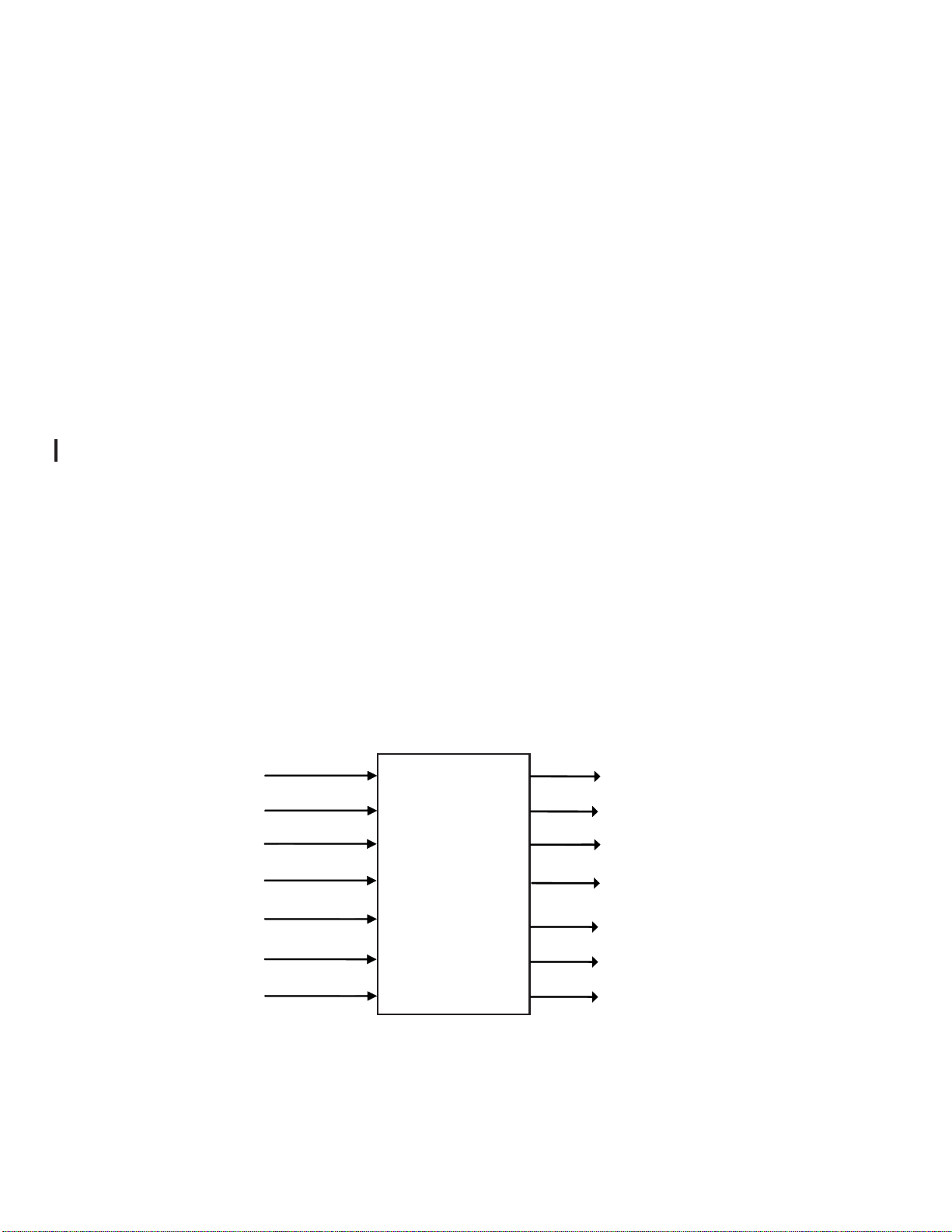
1.2.4 Outputs ............................................................................................................... 7
1.2.4.1 RS 232 .......................................................................................................... 7
1.2.4.1.1 RS 232 (A and B) Airdata Output........................................................ 7
1.2.4.1.2 RS 232 (C and D) Corresponding Altitude Output ............................. 8
1.2.4.2 ARINC 429 High Speed Labels ................................................................... 8
1.2.4.3 Gillham Grey Code Output .......................................................................... 8
1.2.4.4 AIM Output .................................................................................................. 8
1.2.5 Inputs .................................................................................................................. 9
1.2.6 Certification ........................................................................................................ 9
Section 2 Installation Considerations
2.1 Introduction .................................................................................................................... 12
2.2 Mounting Considerations ............................................................................................... 13
2.3 Cooling ......................................................................................................................13
Section 3 Installation Procedures
3.1 General ......................................................................................................................14
3.2 Equipment Required ....................................................................................................... 14
3.2.1 Equipment Supplied ........................................................................................... 14
3.2.2 Equipment Required But Not Supplied .............................................................. 14
3.3 Mounting Tray Installation ............................................................................................. 14
3.4 Static and Pitot Port Connection..................................................................................... 16
3.5 OAT Probe Mounting and Connection ........................................................................... 16
3.6 Electrical Installation......................................................................................................17
3.7 Fuel Flow Interconnect................................................................................................... 18
3.8 Synchro Inputs................................................................................................................ 18
3.9 BARO Interface.............................................................................................................. 18
3.10 Transponder Interconnect ............................................................................................... 19
3.11 AIM Interconnect ........................................................................................................... 19
Section 4 Configuration and Calibration
4.1 Setup for Configuration .................................................................................................. 24
4.2 Changing Configuration Parameters .............................................................................. 24
4.3 Status Line Descriptions................................................................................................. 26
4.3.1 Serial Port Settings ............................................................................................. 27
4.3.2 Airspeed Trim ..................................................................................................... 27
305586-00

List Of Illustrations
Figure 1-1 System Configuration Diagram .............................................................................. 4
Figure 1-2 SAC 7-35 Environmental Qualification Form...................................................... 10
Figure 1-3 OAT Probe Environmental Qualification Form.................................................... 11
Figure 3-1 Mounting Tray Dimensions .................................................................................. 15
Figure 3-2 SAC 7-35 Outline Dimensions ............................................................................. 15
Figure 3-3 OAT Probe Dimensions ........................................................................................ 16
Figure 3-4 OAT Probe Mounting ........................................................................................... 17
Figure 3-5 Fuel Flow Interconnect......................................................................................... 18
Figure 3-6 AIM Interconnect ................................................................................................. 19
Figure 3-7 Gilham Gray Code Interconnect w/ Most Popular Transponders ........................ 20
Figure 3-8 SAC 7-35 Interconnect Wiring Diagram .............................................................. 21
Figure 3-9 Front Panel Connector Location........................................................................... 23
Figure 4-1 6 Pin Din to Serial Interconnect ........................................................................... 24
Figure4-2 RS-232StatusLinesSetting ................................................................................... 26
Figure4-3 SAC7-35Configuration Mode -UnitTrimStatus................................................... 26
Figure4-4 SAC7-35 ConfigurationMode -Fuel UnitStatus ................................................... 26
3
Table Of Contents Con’t
4.3.3 SynchroInputSettings .......................................................................................... 27
4.3.4 AltitudeTrim......................................................................................................... 28
4.3.5 BAROSettingTrim .............................................................................................. 28
4.3.6 Airspeed Cutoff .................................................................................................. 29
4.3.7 Fuel flow Configuration and K-factor ................................................................ 29
4.3.8 List Inputs ........................................................................................................... 29
4.3.9 ARINC Mode ..................................................................................................... 29
4.3.10 OAT Probe Trim ................................................................................................. 30
4.4 Continued Airworthiness ................................................................................................ 30

Section 1 General Description
1.1 INTRODUCTION
This manual describes the installation of the SANDIA aerospace SAC 7-35 Airdata Computer. It is
intended for use by FAA certified repair stations to install the SAC 7-35 Airdata Computer and in-
cludes both the mechanical and electrical installation information for the SAC 7-35. Calibration, sys-
tem configuration and checkout procedures are included. The installer should ensure that all functions
areoperatingaccording to theirintendedpurposeintheirparticularinstallation.
1.1.1 Product Description
TheSAC7-35 is a solidstate -1000 to 35,000footairdata computer andaltitudeencoder. Withtheaddition
ofafuelflowtransducer(s),theSAC7-35willalsoprovidefuelflowdatatosystemscapableofdisplayingthat
information. TheSAC7-35providesfivedataoutputsthatallow ittointerfacewithawide rangeoftranspon-
ders,TAWS,MFD’s,Navigation Systems anda variety ofother avionics products. TheSAC 7-35 canalso
beinstalledforuseinavarietyofconverterfunctions. Contact factory for more information.
• OneARINC 429 High Speed output, airdata and/orADS-B.
• Two RS-232 airdata output ports (including fuel flow or ADS-B).
• Two RS-232 serial encoder outputs
Note:All four of the RS-232 outputs can be individually configured to match the system(s)
being interfaced.
• One Gillham Grey code output for legacy transponders.
• One SANDIA Altitude In-flight Monitoring (AIM) feature. With the addition of an optional
panel mounted switch and annunciator the AIM mode will monitor and advise the pilot if the
aircraft deviates from a selected altitude.
All calibration and configuration is accomplished via a lap top computer through the 6 pin Din connec-
tor on the front of the SAC 7-35.
SAC 7-35
Airdata Computer
Pitot
Static
OAT
Syncro Heading
Baro Pot *
Fuel **
GPS Track
Grey Code to Transponder
RS 232 Corresponding Alt. C
RS 232 Airdata A
RS 232 Airdata B
ARINC 429 Airdata
AIM (Altitude In-flight
Montoring)
* Optional
** Single or Twin
Figure 1-1
System Configuration
RS 232 Corresponding Alt. D
305586-004

5
1.2 TECHNICAL CHARACTERISTICS
1.2.1 Physical Characteristics
1.2.1.1 SAC 7-35
Width: 4.87”(5.11”withmountingtray)
Height: 1.89” (2.35” with mounting tray)
Depth: 5.62” (5.62” with mounting tray)
Weight: 1.18lbs. (1.39lbs. with mounting tray)
1.2.1.2 STP 78 OAT Probe
SeeFig3.3forDimensions
Weight: .067lbs
1.2.2 Operational Characteristics
Operating Temp. -20o C to + 55oC
Input Voltage: 11 - 32 Vdc
Current 1.0 amp maximum with heater on
Altitude Range -1000’ to 35,000’
PressureAltitude Tolerance: 0’ +/- 25’
2000’ +/- 25”
3000‘ +/- 30’
4000’ +/- 25’
5000’ +/- 25’
8000 +/- 30’
11000’ +/- 35’
14000’ +/- 40’
17000’ +/- 45’
20000’ +/- 50’
30000’ +/- 100’
40000’ +/- 125’
Resolution: Grey Code 100’
RS232 10’
ARINC 429 1’
Density Altitude Accuracy Pressure Alt Correction Tolerance
1000’- 18000’(PAlt) 250 ft. max.
Maximum Vertical Speed: 9,999 fpm Serial
20,000 fpm ARINC 429
Accuracy ±1000 ft/min at ±20000 ft/min
±0300 ft/min at ±6000 ft/min
±0200 ft/min at ±4000 ft/min
±0100 ft/min at ±2000 ft/min
±0050 ft/min at ±1000 ft/min
±0045 ft/min below ±1000 ft/min

305586-006
Indicated Airspeed: 0-450 KTS
0.088-.999 MACH
Accuracy Kts Accuracy
50 5.0
80 3.5
100 2.0
120 2.0
150 2.0
200 2.0
250 2.4
300 2.8
350 3.2
400 3.6
450 4.0
MACH Number Accuracy MACH Tolerance
0.3 to 0.4 0.012
.0.5 0.010
0.6 0.0075
0.7-0.9 0.0050
.95 0.0075
True Airspeed Accuracy ALTIAS TAS TAS Accuracy
10000 50 53 6.6
10000 100 105 3.0
10000 200 211 3.3
10000 300 314 4.6
10000 400 416 5.9
10000 450 467 6.5
30000 50 80 10.1
30000 100 160 4.6
30000 200 315 5.2
30000 300 460 6.9

1.2.4 Outputs
1.2.4.1 RS-232
1.2.4.1.1 RS-232 (A & B) Airdata
The airdata outputs supported by the SAC 7-35 are Garmin Z-message, Garmin-G and
King D. Each of these output formats work with ‘Aviation’format input.
The SAC 7-35 will also interface to a Garmin ADS-B serial output on port -B at 9600
baud. When connected to ADS-B input no serial data is output on port-B.
Baud Rate Installation Configurable to 1200, 9600, 19200 or 38400
Data Bits 8
Stop Bit 1
Parity None
Output Rate: 1 +/- .2 seconds
Altitude Resolution 10”
Airspeed Resolution 1 Kt
7
1.2.2 Operational Characteristics con’t
Wind Speed: 0-200 KTS
Accuracy 6.5 Kts
Wind Direction Accuracy 10 degrees
Air Temp:
Range: -60oC to +60oC
Accuracy +1.5oC
Fuel Flow:
Flow Rate: 1-14400 GPH
K-Factor Range 500-130,000
Outside Air Temperature -60oC - +60oC
Accuracy 1.5oC
1.2.3 Operating Limitations
1.2.3.1 All functions of the SAC 7-35 meet the appropriate design assurance qualifications for a
secondary system for airplanes in Class I, Class II and Class III in accordance with AC
23.1309-1D, Figure 2. The TSO authorization with the RTCA/DO178B software levels by
functions are listed in Section 1.2.6
1.2.3.2 The SAC 7-35 is for navigation information only and not for primary flight information.
1.2.3.3 Fuel flow limited to 2000 input pulses per second.
The SAC 7-35 fuel flow conversion is limited to 2000 input pulses per second
For example, do not install where the K factor and maximum fuel flow exceed:
500K — 14,400 gph 19700K — 365 gph
84600K — 85 gph 130000K — 55 gph

1.2.4.2 ARINC 429, High Speed
If Selected, the following 100 kbit/sec (High Speed) ARINC 429 Airdata Labels are transmit-
ted by the SAC 7-35:
305586-008
1.2.4.1.2 RS 232 (C & D) CorrespondingAltitude
The SAC 7-35 supports Garmin and Garmin AT RS232 Corresponding Altitude formats.
Baud Rate Installation Configurable to 1200, 9600, 19200 or 38400
Data Bits 8
Stop Bit 1
Parity None
Output Rate: 1 +/- .2 seconds
Altitude Resolution 10”
Label Parameter Units Repeat Rate Range Resolution
162 Density Altitude Feet 62.5ms 131072 1
203 Pressure Altitude Feet 62.5ms 131072 1
204 Baro Altitude Feet 62.5ms 131072 1
205 MACH Number Mach 62.5ms 4.0 6.25E-5
206 IAS Knots 62.5ms 1024 0.0625
210 True Airspeed Knots 62.5ms 2048 0.0625
211 Total Air Temp degC 500ms 512 0.25
212 Altitude Rate ft/min 62.5ms 32768 16
213 Static Air Temp degC 500ms 512 0.25
235 Baro Setting InHg 62.5ms 39.999 0.001
244 Total Fuel Flow Lb/hr 62.5ms 32768 0.5
315 Wind Speed Knots 500ms 256 1
316 Wind Direction Deg True 500ms 360 0.05
320 Magnetic Heading Deg Mag 62.5ms 360 0.0055
347 L/R Fuel Flow Lb/hr 62.5ms 32768 0.5
If selected, the following 100 kbit/sec (High Speed) ARINC 429/743ADS-B Labels are trans-
mitted by the SAC 7-35 (-01 version only):
Label Parameter Units Repeat Rate Range Resolution Data bits
103 Ground Track Degrees as received 180 0.0055 15
110 Latitude degrees as received 180 1.7E-4 20
111 Longitude degrees as received 180 1.7E-4 20
112 Ground Speed knots as received 4096 0.125 15
120 Fine Latitude degrees as received 1.7E-4 8.4E-8 11
121 Fine Longitude degrees as received 1.7E-4 8.4E-8 11
130 Horiz Prot Level nm 1 sec 16 1.22E-4 17
133 Vert Prot Level feet 1 sec 32768 0.125 18
136 Vert. Fig of Merit feet 1 sec 32768 0.125 18
165 Vert Velocity fpm as received 32768 1 15
166 North/South Velocity knots as received 4096 0.125 15
174 East/West Velocity knots as received 4096 0.125 15
247 Horiz Fog of Merit nm 1 sec 16 6.10E-5 18
273 GPS Status discr 1 sec discr discr discr
335 Track Angle Rate deg/s as received 32 0.015625 11
370 GPS Height feet as received 131072 0.125 20
(Alternates L/R)

1.2.6 Certification
TSO C88a (Encoder)
TSOC106 (AirdataComputer)
ETSO C88a
ETSO C106
Hardware DO 160E
Software DO 178B Level C
ComplexHardware DO-254 Level C
9
1.2.5 Inputs
Static Pressure -1000 to 35,000 feet
Pitot Pressure 0 to 450 Kts
Outside Air Temp (OAT) -60O to +60O C
Heading ARINC 407 Syncro (line voltage 11.8 Vrms)
Leg H 10 ΚΩ
Leg X 17 ΚΩ
Leg Y 17 ΚΩ
Fuel Flow 0 to 14400 GPH (2000 pulses/sec max)
K-factor 500-130000
Baro 0 to +5Vdc Baro Pot
AIM Pushbutton Active Low with Internal Pull Up
Strobe From On board Transponder
“The conditions and test required for TSO approval of this article are mini-
mum performance standards. It is the responsibility of those desiring to
install the article either on or within a specific type or class of aircraft to
demonstrate that the aircraft installation conditions are within the TSO stan-
dards. The article may be installed only if installation of the article is
approved by the Administrator.”
1.2.4.4 AIM Outputs
Maximum Lamp Current:80 mA
Maximum off Voltage: 50V
1.2.4.3 Gillham Grey Code Outputs
a. 10 Bits available: D4,A4, A2, A1, B4, B2, B1, C4, C2, C1
b. Bit On Impedance: Less than 5 ohms
c. Bit Off Leakage: Less than 10uA
d. Maximum Current per bit: 20 mA
e. Minimum working current: 10 uA
f. Maximum voltage per bit: 50V
g. Minimum working voltage: 5V
h. Bit update rate: Less than 250 mS
i. Minimum strobe switching bandwidth: Greater than 10kHz

Environmental Qualification Form for the SAC 7-35 Airdata Computer
NOMENCLATURE: SAC 7-35,Airdata Computer
TYPE/MODEL/PART NO: SAC 7-35 / 305548-00
TSO NUMBER: C88a, C106
MANUFACTURER’S SPECIFICATION AN/OR OTHER APPLICABLE SPECIFICATION:
SAC 7-35 INSTALLATION MANUAL P/N 305586-00
QUALIFICATION TEST PLAN, 901000-QTP
MANUFACTURER: SANDIA AEROSPACE
ADDRESS: ALBUQUERQUE, NM 87109
REVISION & CHANGE NUMBER OF DO-160: REV E
305586-0010
Figure 1-2
SAC 7-35 Environmental Qualification Form
snoitidnoCnoitceSnoitpircseD
edutitlAdnaerutarepmeT00.44CyrogetaC
erutarepmeTwoL1.5.4pmeTdloCnoitarepOC02-
erutarepmeThgiH
gnilooCfossoLthgilF-nI noisserpmoceDedutitlA erusserprevO
3.5.4&2.5.4
4.5.4
1.6.4 2.6.4 3.6.4
pmeThgiHgnitarepOC55+ pmeTwoLPOemiTtrohSC04- pmeThgiHpOemiTtrohSC55+ oLlavivruSdnuorGC55- hgiHlavivruSdnuorGC58+
elbacilppAtoNtseT
teef000,53 elbacilppAtoNtseT elbacilppAtoNtseT
noitairaVerutarepmeT0.5niM/C2CyrogetaCotdetseT
ytidimuH0.6AyrogetaCotdetseT
ytefaShsarCdnkcohSlanoitarepO0.7tfarcriA,AyrogetaCottseT noitatneirOmodnaR.5epyT
noitarbiV0.8gnisu2enoZtfarcriA,2U&SseirogetaCotdetseT 1F&F,Msevrucnoitarbiv
noisolpxE0.9demrofreptseton,XyrogetaCsadeifitneditnempiuqE
ssenfoorpretaW0.01demrofreptseton,XyrogetaCsadeifitneditnempiuqE
ytilibitpecsuSsdiulF0.11demrofreptseton,XyrogetaCsadeifitneditnempiuqE
tsuDdnadnaS0.21demrofreptseton,XyrogetaCsadeifitneditnempiuqE
sugnuF0.31demrofreptseton,XyrogetaCsadeifitneditnempiuqE
yarpStlaS0.41demrofreptseton,XyrogetaCsadeifitneditnempiuqE
tceffEcitengaM0.51noitcelfeDM3.0<ZyrogetacsitnempiuqE
tupnIrewoP0.61ByrogetaCotdetseT
ekipSegatloV0.71AyrogetaCotdetseT
ytilibitpecsuSycneuqerFoiduA0.81ByrogetaCotdetseT
ytilibitpecsuSlangiSdecudnI0.91CByrogetaCotdetseT
ytilibitpecsuSycneuqerFoidaR0.02TTyrogetaCotdetseT
noissimEycneuqerFoidaR0.12MyrogetaCotdetseT
y
tilibitpecsuStneisnarTdecudnIgninthgiL0.22demrofreptseton,XyrogetaCsadeifitneditnempiuqE
stceffEtceriDgninthgiL0.32demrofreptseton,XyrogetaCsadeifitneditnempiuqE
gnicI0.42demrofreptseton,XyrogetaCsadeifitneditnempiuqE

Environmental Qualification Form for the STP 78 OAT Probe
NOMENCLATURE: Outside Air temperature Probe
TYPE/MODEL/PART NO: STP 78 OATProbe /305561-01
TSO NUMBER: C88a, C106
MANUFACTURER’S SPECIFICATION AN/OR OTHER APPLICABLE SPECIFICATION:
SAC 7-35 INSTALLATION MANUAL P/N 305586-00
QUALIFICATION TEST PLAN, 901000-QTP
MANUFACTURER: SANDIA AEROSPACE
ADDRESS: ALBUQUERQUE, NM 87109
REVISION & CHANGE NUMBER OF DO-160: REV E
11
Figure 1-3
OAT Probe Environmental Qualification Form
SNOITIDNOCNOITCESDETCUDNOCSTSETFONOITPIRCSED
edutitlAdnaerutarepmeT erutarepmeTwoL erutarepmeThgiH
gnilooCfossoLthgilF-nI edutitlA noisserpmoceD erusserprevO
0.4 1.5.4 3.5.4&2.5.4
4.5.4 1.6.4 2.6.4 3.6.4
2CyrogetaC pmeTwoLgnitarepOC55- pmeThgiHgnitarepOC07+ pmeTwo
LpOemiTtrohSC55- pmeThgiHpOemiTtrohSC07+ woLlavivruSdnuorGC55 hgiHlavivruSdnuorGC58+
elbacilppAtontseT tee
f000,53 elbacilppAtontseT elbacilppAtontseT
noitairaVerutarepmeT0.5niM/C01AyrogetaCotdetseT 53-7CASmorfyletarapesdetseT
ytidimuH0.6CyrogetaCotdetseT 53-7CASmorfyletarapesdetseT
ytefaShsarCdnakcohSlanoitarepO0.7noita
tneirOmodnaR.5epyTtfarcriA,AyrogetaCottseT
noitarbiV0.8 noitarbivgnisu1enoZtfarcriA,2U&SseiyrogetaCotdetseT 1F&F,Msevruc
noisolpxE0.9demrofreptseton,XyrogetaCsadeifitneditnempiuqE
ssenfoorpretaW0.01demrofreptseto
n,XyrogetaCsadeifitneditnempiuqE
ytilibitpecsuSsdiulF0.11demrofreptseton,XyrogetaCsadeifitneditnempiuqE
tsuDdnadnaS0.21demrofreptseton,XyrogetaCsadeifitneditnempiuqE
sugnuF0.31demrofreptseton,XyrogetaCsadeifitne
ditnempiuqE
yarpStlaS0.41demrofreptseton,XyrogetaCsadeifitneditnempiuqE
tceffEcitengaM0.51Zyrogetacsitnempi
uqE
tupnIrewoP0.61demrofreptseton,XyrogetaCsadeifitneditnempiuqE
ekipSegatloV0.71demrofreptseton,XyrogetaCsadeifitneditnempiuqE
ytilibitpecsuSycneuqerFoiduA0.81ByrogetaCotdetseT
ytilibitpecsuSlangiSdecudnI0.91CByrogetaCotdetseT
ytilibitpecsuSycneuqerFoidaR0.02TTyrogetaCotdetseT
noissimEycneuqerFoidaR0.12MyrogetaCotdetse
T
ytilibitpecsuStneisnarTdecudnIgninthgiL0.22demrofreptseton,XyrogetaCsadeifitneditnempiuqE
stceffEtceriDgninthgiL0.32demrofreptseton,XyrogetaCsadeifitneditnempiuqE
gnicI0.4demrofreptseton,XyrogetaCsadeifitnedit
nempiuqE

Section 2 Installation Considerations
2.1 INTRODUCTION
The SAC 7-35Airdata Computer enhances installations that include GPS, TWAS, Moving Map
Displaysandother avionicsthatcanutilizeairdatainformation. Additionally,theSAC 7-35isTSO’d
and ETSO’d as anAltitude Encoder for use with transponder systems. The SAC 7-35 provides
standardGillhamGrey Code outputonits15pinconnector(P-101)foruse with legacytransponders.
Two independent RS232 corresponding altitude outputs are provided on the 25 pin connector (J-
100). TheRS 232 outputscan be usedon new generation transponders thataccept RS-232 altitude
formatorother systems thatrequirecorrespondingaltitude. TheP-101GreyCodeconnector follows
thestandard interconnectformatusedbymostencodermanufacturers. By followingthisconvention,
upgradingtotheSAC7-35 is made easier. Ifanexistingencoderis being replaced, itisimportantto
checkthewiring informationbeforepluggingtheexistingconnectorintothe SAC7-35.
Two RS232 Airdata and one high-speed ARINC 429 airdata outputs are available from the
SAC 7-35.
Fuel flow data is supported by the SAC 7-35 if pulse type fuel flow transducer(s) are mounted
in the aircraft’s fuel lines. The SAC 7-35 only accepts pulse type fuel information such as that
providedby Flow Scan transducers or through theuse afan appropriate converter. If the aircraft is
equippedwitha Flow Scantransducer(s) the SAC7-35 can paralleloff the signal line. TheSAC 7-
35mustbeconfiguredwiththetransducer(s) K-factor number.
If the aircraft has an altimeter with a 5 VDC baro pot, the SAC 7-35 can use this to provide
corrected altitude output on theARINC 429 bus. The Garmin-Z output format does not support
Baro Correction information. But, when the baro input is avaiable the data will be included in
the King-D and Garmin-G serial RS-232 airdata outputs.
The SAC 7-35 also incorporates SANDIA aerospace’s exclusiveAltitude In-flight Monitoring
(AIM) feature that advises pilots if they deviate from their selected altitude by more than one
hundred feet. The AIM feature can be installed by adding a switch and annunciators to the
aircraft panel.
The SAC7-35 accepts (five wire HSI) heading input in ARINC 407 format. Heading, GPS
ground speed and track inputs are required in order for the SAC 7-35 to calculate winds aloft.
The SAC 7-35 does not require warm up unless the outside temperature is below 20 degrees C.
When warm up time is required, the internal heater is generally capable of warming the SAC 7-
35 from -55 degrees C to operating temperature in less than one minute.
Systems configuration and calibration is accomplished using an installer supplied computer.
The SAC 7-35 is connected to the computer’s 9 pin RS 232 port from the 6 pin DIN connector
located on the front panel of the SAC 7-35.
12

2.2 MOUNTING CONSIDERATIONS
The SAC 7-35 can be mounted in any orientation, either inside or outside the pressure vessel.
Mounting location should be chosen to minimize the static pressure line length from the SAC
7-35 to the altimeter. Be sure to allow an ample service loop on the cable to allow for calibra-
tion of the SAC 7-35. You’ll notice that the SAC 7-35 mounting tray has the same hole pattern
as the SAE 5-35 encoder. This will simplify installations where the SAE 5-35 is being up-
graded with the SAC 7-35.
CAUTION: DO NOT mount the SAC 7-35 in
the direct airstream or near either the hot or
cold air ducts.
The STP78 OutsideAir Temperature (OAT) probe is supplied with the SAC 7-35. It should be
mounted in a location away for the engine exhaust or other area that prevent it from accurately
measuring outside air temperature. The OAT probe should never be mounted on a dark painted
surface. This will cause errors in the OAT measurement.
CAUTION: DO NOT mount the Outside Air
Temperature(OAT) probeneartheaircraftex-
haust or prop wash, dark surfaces, transmit-
ting antennas or cabin heaters.
2.3 COOLING
The SAC 7-35 does not require external cooling.
13 305586-00

Section 3 Installation Procedures
3.1 GENERAL
The SAC 7-35 is supplied with a mounting tray and crimp type mating connectors. It is
important that the proper crimping tools and techniques be observed in attaching wires to the
mating connectors. Failure to do so could result in a failure in the connection and cause inter-
mittent or non operation of the SAC 7-35.
3.2 EQUIPMENT REQUIRED
3.2.1 Supplied
SAC 7-35 System 705548-XX
Includes: SAC 7-35 Airdata Computer 305548-XX
SAC 7-35 Installation Manual 305586-00
SAC 7-35 Installation Kit, Electrical 305588-00
15 Pin Connector Hood 305208
2 each 25 Pin Connector Hoods 305437
25 Pin Female Connector w/Crimp Pins 305583
25 Pin Connector w/Crimp Sockets 305720
15 Pin Male Connector w/Crimp Pins 305721
SAC 7-35 Installation Kit, Mechanical 305589-00
Mounting Tray 305557
Knurled Hold-down Nut 305558
STP 78 OAT Probe 305561-91
OAT Probe Installation Kit 305595-00
Mounting Nut 305560-03
Mounting Lock Washer 305050-10
Fiber Shoulder Washer 305587-03
FlatFiberMountingWasher 305581-04
9 pin RS 232 to 6 pin DIN adapter cable 305580
3.2.2 Required But Not Supplied
Number 6-32 Mounting Screws, 3 or 4 depending on your selected mounting option.
Static Port Fitting
PitotPortfitting
3.3 MOUNTING TRAY INSTALLATION
The mounting tray is mounted to the airframe using either three or four number 6-32 screws.
The mounting hole pattern for the SAC 7-35 mounting tray contains five holes. For new instal-
lations, it is recommended that the four corner holes be used to mount the SAC 7-35 tray. The
fifth hole has been added to facilitate upgrades from some manufactures encoders. Refer to the
SAC 7-35 tray dimensions in Figure 3-1 to determine if the hole pattern of the removed system
match the hole pattern of the SAC 7-35 mounting tray.
14

Figure 3-1
Mounting Tray Dimensions
Figure 3-2
Unit Outline Dimensions
305586-0015
J100 P101
P200
J104
PS
4.98 5.48

3.4 STATIC AND PITOT PORT CONNECTION
Standard 1/8 - 27 NPT brass fittings are provided on the front plate of the SAC 7-35 for attach-
ing to the aircraft static and pitot systems. An adapter may be used to convert these to match the
aircraft static and pitot plumbing. When attaching the mating fittings, make sure that they are
secure and free from leaks that can induce errors in the static and pitot systems. To reduce the
likelihood of the brass fitting rotating while installing the static line, a “D” shaped hole is used
to mount the brass fittings into the front panel. Upon completion of the installation of the SAC
7-35, a Case Leak test is to be performed per FAR Part 43 Appendix E.
NOTE: Since significant force can be applied to the SAC 7-35
duringstatic and pitot fittinginstallation,dual wrenchtechniques
are always recommended to avoid damage to the airdata com-
puter.
3.5 OUTSIDE AIR TEMPERATURE (OAT) PROBE INSTALLATION
The SAE 7-35 is supplied with the STP 78 OAT probe P/N 305561-91. Avoid mounting the
OAT probe in or near prop airstream, engine or heater exhaust, transmitting antennas or on dark
painted surface. Failure to do so will result in improper OAT readings. The OAT probe re-
quires a 7/16” hole be drilled in the skin of the aircraft. The installer should consider fabricating
an appropriate doubler plate in accordance with accepted installation practices as outlined in
AC 43.13-1B. Skin thickness including doubler should be a minimum of 0.050” and a maxi-
mum of 0.188”. See figure 3-4 for mounting details. The OAT probe comes with a three wire
pigtailapproximately2feetinlength. Theinstallercancutthiscabletolengthorextenditby adding
additionalwire. Make sure thatany connectionsare away from areas thatcan accumulate water or
chemicals.
Figure 3-3
STP 78 OAT Probe Dimensions
16
305561-91

The SAC 7-35 uses crimp type Sub-D connectors with screw lock assemblies. The proper
crimp tool for use with machined Sub-D connector pin and sockets is required to ensure that the
wire and connector have good electrical and mechanical bond.
3.6 ELECTRICAL INSTALLATION
The SAC 7-35 is designed to operate from 11-32 Vdc without any special wiring consider-
ations. Power can be supplied from the aircraft buss through a 2Amp circuit breaker. Since the
SAC 7-35 is TSO’d as an encoder, power can also be supplied from the onboard transponder. If
power is supplied from the transponder, the SAC 7-35 and it’s airdata functions will not operate
if the transponder is turned off or removed from the aircraft.
NOTE: Ifthe powersourceforthe SAC 7-35 is fromthe on board
transponder, the SAC 7-35 and it’s airdata outputs will not be
available if the transponder is turned off or removed from the
aircraft.
SAE documentAS8003 Minimum Performance Standard for Automatic Pressure Altitude Code
Reporting Equipment states that “a means shall be incorporated in the equipment to indicate the
loss of electrical power or the effect thereof, unless the electrical power to operate the code
generating equipment is supplied by an ATC Transponder which also supplies an indication of
this power loss.” The two power pins 14 and 8 on P101 are internally connected in the SAC 7-
35. Only one of these connections is necessary to supply power to the unit. The unused con-
nection can be used to drive a panel-mounted indicator if desired.
Shoulder Washer
Insulating Washer
Lock Washer
Nut
Figure 3-4
STP 78 OAT Probe Mounting
305586-0017
Installation to be in accordance with FAA
AC 43.13-1B
Table of contents
Popular Desktop manuals by other brands

STRUCTUBE
STRUCTUBE UPP quick start guide

Ergotron
Ergotron 48 Unit Management Cart manual

Müller-Elektronik
Müller-Elektronik UNI-Control S Installation and user guide

Dell
Dell D10U003 Setup and specifications guide

HPE
HPE Synergy 480 Gen10 series Maintenance and service guide

Lenovo
Lenovo ThinkCentre M57 Guide d'utilisation