Sandrigarden HTG 26/55 User manual

1
HTG 26/55
6035670/113
TAGLIASIEPI - HEDGETRIMMER
TAILLE-HAIE - HECKENSCHNEIDERS
HEGGENSCHAAR - HÆKKEKLIPPERE
PODADERA - CORTA SEBES
NO¯YCE DO ¯YWOP£OTU
MANUALE ISTRUZIONI
INSTRUCTION MANUAL
MODE D'EMPLOI
BEDIENUNGSSANLEITUNGEN
GB
I
F
D
NL
E
P
PL
BEDIENINGSHANDLEIDING
BRUGERVEJLEDNING
MANUAL DE INSTRUCCIONES
MANUAL DE INSTRUÇÕES
INSTRUKCJA OBS£UGI
Leggereattentamentelepresentiistruzioniprimadelprimoimpiego.
Readthisoperatormanualcarefullybeforethefirstuse.
Lireavecattentioncesinstructionsavantlapremièreutilisation
VorderAnwendungdievorliegendenAnweisungenaufmerksamlesen.
Leesaandachtigdezeinstructiesdooralvorenshetapparaatvoorheteerstingebruiktenemen.
lÆSOMHYGGELIGTDENNEbrugerVEJLEDNINGINDENAPPARATETSÆTTESIBRUG
Leerconcuidadoestasinstruccionesantesdelaprimerautilización.
Leiacomatençãoestasinstruçõesantesdeutilizarpelaprimeiravezoaparelho.
Przedpierwszymu¿ytkowaniemuwa¿nieprzeczytaæniniejsz¹instrukcjê.
I
GB
F
D
NL
DK
E
P
PL
DK

2
(I)
ATTESTAZIONE DI CONFORMITÀ ALLE NORME CEE
Lasottoscritta SANDRIGARDEN srl, via Manzoni 22, 36027ROSÀ (VI) ITALIA, dichiara che iseguenti prodotti:
TAGLIASIEPIHTG26/55 sonoconformialledirettive,98/37/CEE,89/336/CEE,esonostatisviluppaticonforme-
menteallenormeEN774
(ENG)
EC DECLARATION OF CONFORMITY
The under signed SANDRIGARDEN srl, via Manzoni 22, 36027 ROSÀ (VI) ITALIA, declare that the following
products:HEDGETRIMMERHTG26/55 areinaccordancewiththedirective98/37/EEC, 89/336/EECandhavebeen
devellopedinaccordancewiththestandarsEN774.
(F)
ATTESTATION DE CONFORMITE AUX NORMES CEE
LasoussignéeSANDRIGARDEN srl,viaManzoni22,36027ROSÀ(VI)ITALIE,déclarequecesproduitsTAILLE-
HAIEHTG26/55 sontconformesauxdirectives,98/37/CEE,89/336/CEE,etconçuselonlesnormesEN774.
(D)
KONFORMITÄTBESCHEINIGUNGZUEWG-REGELUNGEN
DieunterschriebeneFirmaSANDRIGARDENsrl,viaManzoni22,36027ROSÀ(VI)ITALIEN,erklärthiermit,dass
folgendesProdukt::HECKENSCHNEIDERSHTG26/55 denRichtlinien98/37/EWG,89/336/EWGentsprichtunddass
esentsprechenddenStandardsEN774entwickeltwurde.
(NL)
CONFORMITEITSVERKLARING MET DE CEE NORMEN
Ondergetekende SANDRIGARDEN srl, via Manzoni 22, 36027 ROSÀ (VI) ITALIË, verklaart dat de volgende
producten:HEGGENSCHAARHTG26/55 conformzijnaanderichtlijnen98/37/CEE,89/336/CEE,enontworpenzijn
inovereenstemmingmetdenormenEN774.
(E)
CERTIFICACIÓN DE CONFORMIDAD CON LAS NORMAS CEE
LaabajofirmanteSANDRIGARDENsrl,viaManzoni22,36027ROSÀ(VI)ITALIA,declaraqueelsiguienteproducto:
PODADERAHTG26/55 sonconformesalasdirectivas,98/37/CEE,89/336/CEE,yhasidorealizadodeconformidad
conlasnormasEN774.
(P)
ATESTADO DE CONFORMIDADE COM AS NORMAS CEE
A abaixo assinada SANDRIGARDEN srl, via Manzoni 22, 36027 ROSÀ (VI) ITÁLIA, declara que os seguintes
produtos:CORTASEBES HTG26/55 estãoconformeasdirectivas98/37/CEE,89/336/CEE,eforamdesenvolvi-
dosdemaneiraconformeasnormasEN774.
(PL)
CERTYFIKAT ZGODNOCI Z NORMAMI CEE
Ja, ni¿ej popisany/a SANDRIGARDEN srl, ulica Manzoni 22, 36027 ROSA (V ) W£OCHY,
owiadcza, ¿e produkt: NO¯YCE DO ¯YWOP£OTU HTG26/55 s¹ zgodne z dyrektywami 98/
37/CEE, 89/336/CEE i zosta³y zbudowany zgodnie z normami EN 774.
24 - 11 - 2003
SANDRI GARDEN
srl
Direttore Generale
Alberto Cattaneo
(DK)
overensstemmelseserklÆringmedeØfstandardnormer
undertegnede SANDRIGARDEN srl, via Manzoni 22, 36027 ROSÀ (VI) ITALIA, erklÆrer at fØlgende produkt:
HÆKKEKLIPPEREHTG26/55erioverensstemmelsemedeuropadirektiverneeØF/98/37,eØf/89/336,ogatdener
blevetbyggetioverensstemmelsemednormenEN774

3
123 5 9
4
6
78
1011
12
13
14
16
15
Fig. 1
17
PARTI MACCHINA - MACHINE PARTS - PIECES DE LA MACHINE
MASCHINENTEILE-MACHINEDELEN-MASKINENSENKELTDELE
PARTES MÁQUINA - PARTES DA MÁQUINA- CZÊCI URZ¥DZENIA

4
ILLUSTRAZIONI DI FUNZIONAMENTO E MANUTENZIONE - ILLUSTRATION OF OPERATION
& MAINTENANCE - ILLUSTRATIONS DE MARCHE ET DE MAINTENANCE - BETRIES-UND
WARTUNGSANLEITUNGEN-AFBEELDINGEN VANDE WEKING EN HET ONDERHOUD
BILLEDER TIL BETJENING OG VEDLIGEHOLDELSE - ILLUSTRACIONES DE
FUNCIONAMIENTO Y MANTENIMIENTO - ILUSTRAÇÕES DE FUNCIONAMENTO E
MANUTENÇÃO- RYSUNKI PRZEDSTAWIAJ¥CE DZIA£ANIE ORAZ CZYNNOCI
KONSERWATORSKIE
Fig. 3 Fig. 4
Fig. 2
1
è

5
ILLUSTRAZIONI DI FUNZIONAMENTO E MANUTENZIONE - ILLUSTRATION OF OPERATION
& MAINTENANCE - ILLUSTRATIONS DE MARCHE ET DE MAINTENANCE - BETRIES-UND
WARTUNGSANLEITUNGEN-AFBEELDINGEN VANDE WEKING EN HET ONDERHOUD
BILLEDER TIL BETJENING OG VEDLIGEHOLDELSE - ILLUSTRACIONES DE
FUNCIONAMIENTO Y MANTENIMIENTO - ILUSTRAÇÕES DE FUNCIONAMENTO E
MANUTENÇÃO-RYSUNKI PRZEDSTAWIAJ¥CE DZIA£ANIE ORAZ CZYNNOCI
KONSERWATORSKIE
Fig. 5
Fig. 6
Fig. 7
Fig. 8
Fig. 9
2
1
B
1
A

6
MANUALE ISTRUZIONI TAGLIASIEPI
1. CONGRATULAZIONI
Gentilecliente,vogliamocongratularciconLeiper
aversceltounnostroprodottoperilgiardino.
IlVostroTAGLIASIEPIHTG26/55èstatocostrui-
to,tenendocontodellenormedisicurezzavigentia
tuteladelconsumatore.
In questo manuale sono descritte ed illustrate le
varieoperazionidimontaggio, diusoedinterventi
dimanutenzione,necessaripermantenereinper-
fettaefficienzailVostroTAGLIASIEPI.
PERFACILITARELALETTURA
Leillustrazionicorrispondentialmontaggioealla
descrizionedellamacchinasitrovano,all'iniziodel
presentefascicolo.
Consultarequeste paginedurantela letturadelle
istruzionidimontaggioediutilizzo.
Nel caso il Vostro TAGLIASIEPI necessitasse di
assistenzaoriparazione,Vipreghiamodirivolger-
vial nostro rivenditoreo ad uncentroassistenza
autorizzato.
2. PRECAUZIONI FONDAMENTALI
DISICUREZZA
NORMEGENERALI
AVVERTENZE:
A1 -L'utilizzo del TAGLIASIEPI può
provocare seri danni alle persone, è
pertanto richiesto il rispetto delle se-
guentinormedisicurezza:
A2-Chiunqueutilizziocomunquemet-
tainmotoilTAGLIASIEPIdeveprima
leggereattentamenteilmanualediistru-
zioniemanutenzionee familiarizzare
completamenteconicomandi per un
usocorrettodell'apparecchio.
A2.1- Conservareilpresentemanua-
leperconsultazionifuture.
A3 - Non permettere l'uso del
TAGLIASIEPI aibambiniedaperso-
nechenonsianocompletamenteaco-
noscenzadellepresentiistruzioni.
PERICOLO:
A4-Nonmettereinmotoenonutilizza-
rel'apparecchio inprossimitàdiperso-
ne(specialmentebambini)edanimali.
Duranteilfunzionamentosiraccoman-
daunadistanzaminimadi10m trala
macchinaedaltrepersone.
A5-Siraccomandalamassimaatten-
zione verso possibili pericoli che non
possano essere uditi a causa del ru-
moredell'apparecchio.
A6-Eliminarequalsiasipericolo,cavi,
cavielettricidallazonadilavoro.
A7-L'operatoreèresponsabileincaso
di incidenti o pericoli occorsi ad altre
personeodallelorocose.
UTILIZZO:B1 - Impiegare il TAGLIASIEPI sola-
mente per tagliare siepi, arboscelli e
cespugli.
Nonimpiegarel'apparecchioperscopi
diversi.
B2-Indossareun'abbigliamentoedun
equipaggiamento di sicurezza adatto
all'utilizzodelTAGLIASIEPI.
Durante l'utilizzo indossare abiti ade-
renti e non sciolti. Non indossare og-
gettichepossanoimpigliarsinelleparti
inmovimento.
B3-Indossareocchialidiprotezioneo
visieraomologati.
I
10m

7
MANUALE ISTRUZIONI TAGLIASIEPI
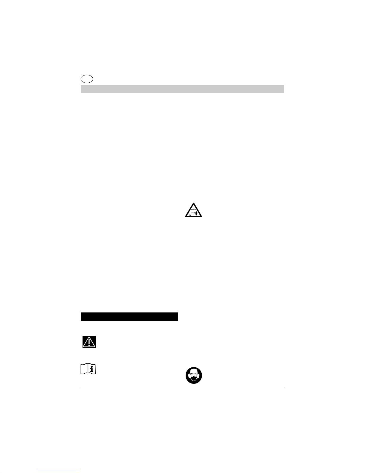
B3.1-Indossareparaorecchidiprote-
zioneperilrumore,omologati.
B3.2-Indossareilcascodiprotezione
incasodirischiodicadutadioggetti.
B4-Calzarescarperobusteconsuole
nonsdrucciolevoli.
B5-Indossareguantirobusti.
B6-ChiutilizzailTAGLIASIEPIdeve
essereinbuonaforma.NONUTILIZ-
ZARE l'apparecchio in condizioni di
stanchezza,dimalessereosottol'effet-
todialcooledidroghe.
B7 - ATTENZIONE! I gas di scarico
sonovelenosiedasfissianti.Seinspi-
ratipossonoquindiessereanchemor-
tali.Nonfarefunzionareilmotoreinluo-
gochiusooscarsamenteventilato.
B8-L'utilizzoprolungatodell'apparec-
chiopuòcausaredisturbidicircolazio-
nesanguignaallemani(malattiadelle
ditabianche)attribuibiliallevibrazioni.
Fattoricheinfluisconosullamanifesta-
zionedeidisturbipossonoessere:
-Predisposizionepersonaledell'ope-
ratoreadunascarsairrorazionesan-
guignadellemani.
-Utilizzodell'apparecchioabassetempe-
rature(siconsiglianopertantoguanticaldi).
-Lunghitempidiutilizzosenzainter-
ruzioni(siconsigliaunutilizzoadin-
tervalli).
-Incasodimanifestazionediformicolio
eintorpidimentosiraccomandadicon-
sultareunmedico.
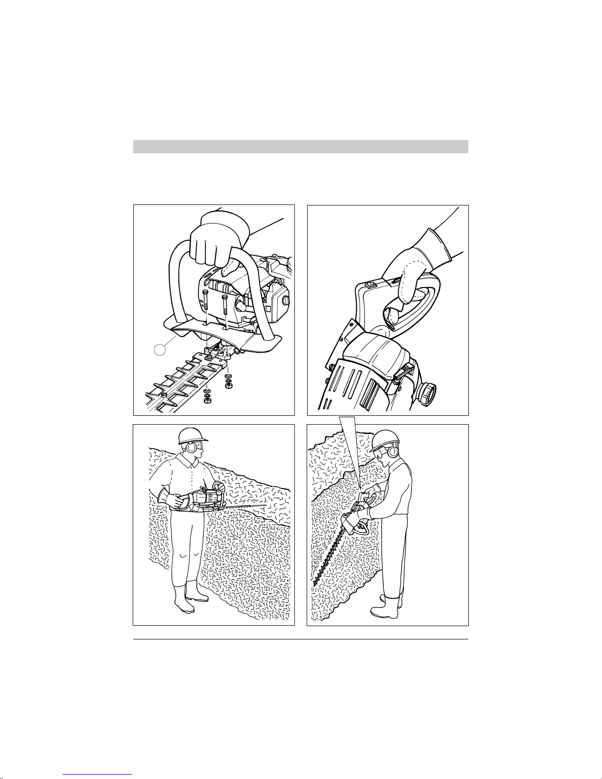
B8.1 - Sostenere l'apparecchio sem-
preconambeduelemani.
Assumereunaposizionestabileesicu-
rasuentrambelegambe.Nonsbilan-
ciarsi.Non operare su scale instabili.
Pertagliaresiepialte,preferireunasta-
bileimpalcatura.
B9 - ATTENZIONE! la benzina e
isuoivaporisonoestremamenteinfiam-
mabili.
PERICOLO DI USTIONI ED INCENDIO.
B9.1-Arrestareilmotoreprimadelri-
fornimento.
B9.2 - Non fumare durante il riforni-
mentodicarburante.
B9.3 - Asciugare il carburante even-
tualmenterovesciato.Mettereinmotoil
motorelontanodalluogodirifornimento.
B9.4-Assicurarsicheiltappodelser-
batoiosiabenserrato.
Fareattenzioneadeventualiperdite.
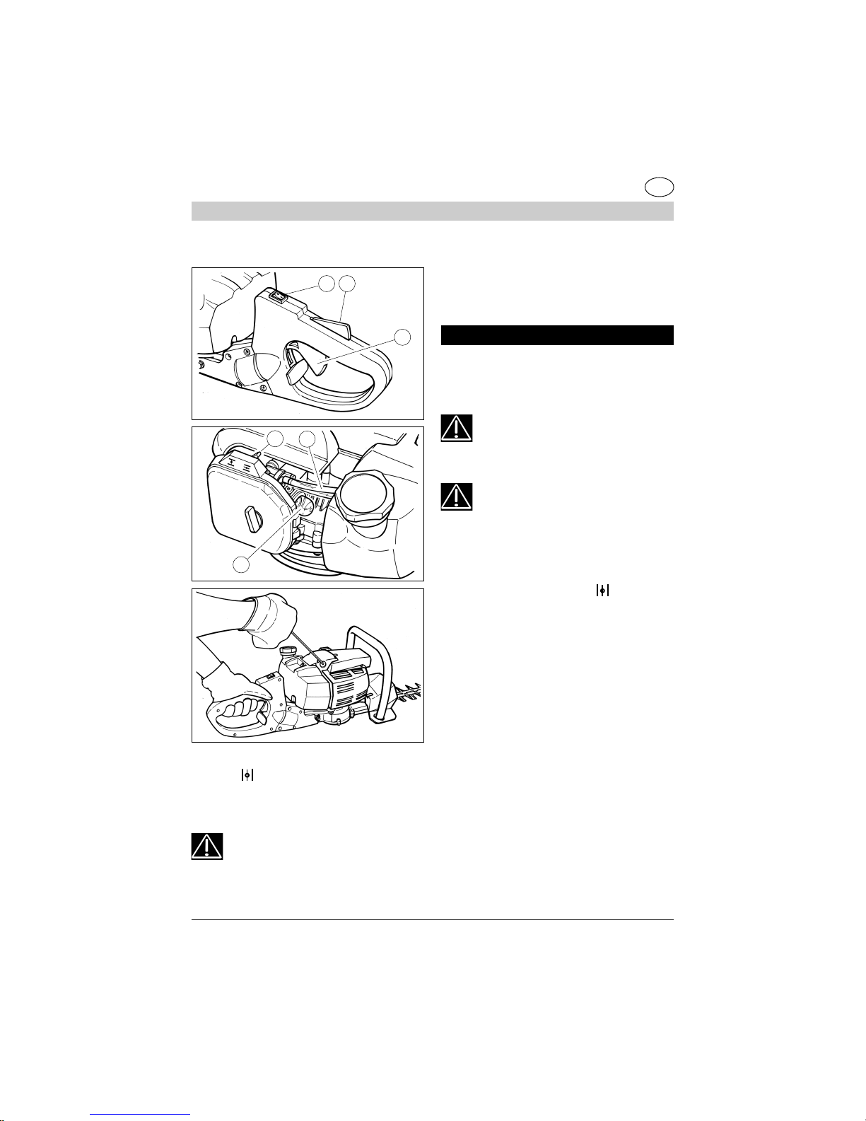
B10 - DISPOSITIVI DI SICUREZZA
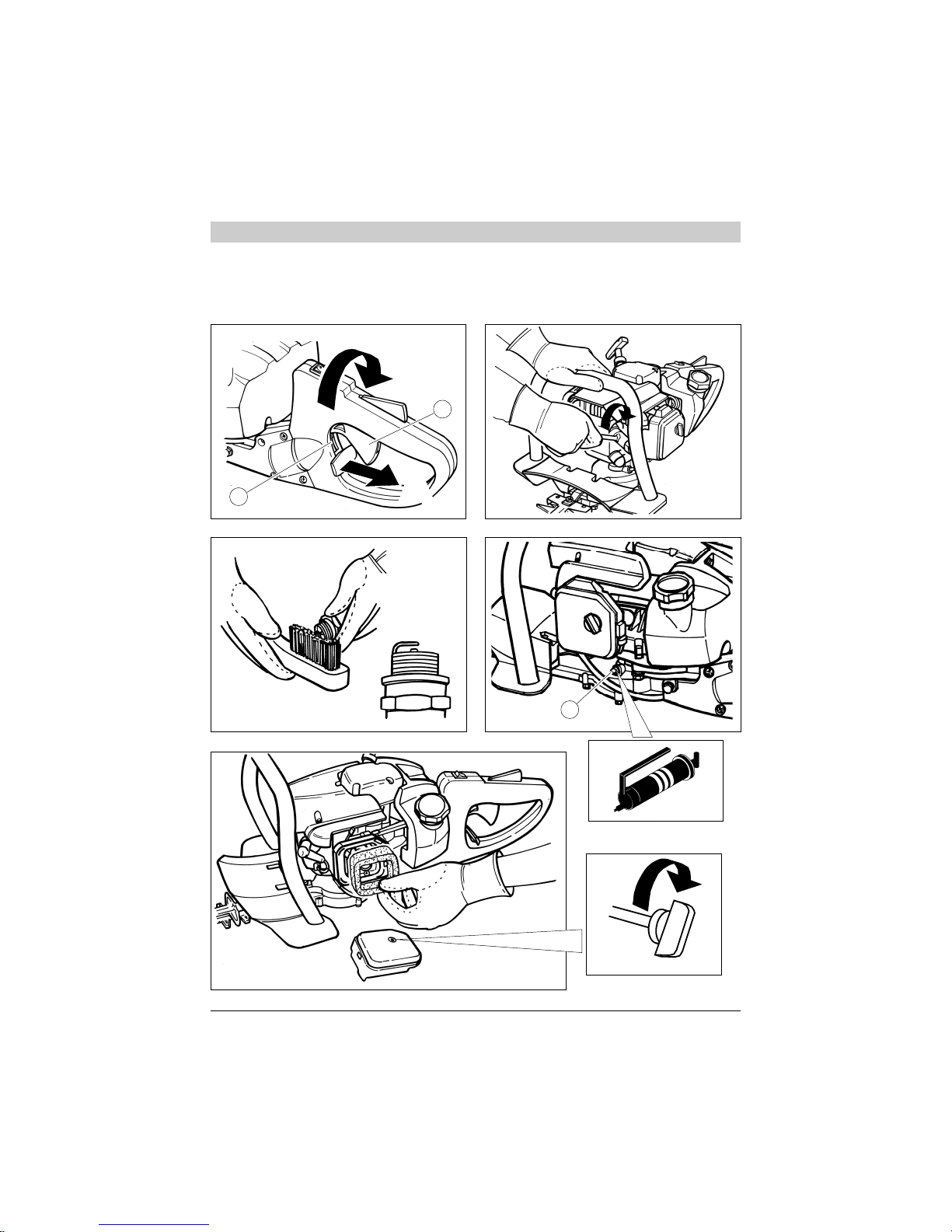
B10.1 - IlBLOCCO DEL COMANDO
DELL'ACCELERATORE (vedi fig.1
part.17)impediscel'azionamentoacci-
dentaledellalevadell'acceleratore.
B10.2 - INTERRUTTORE (ON/OFF)
diarrestodelmotore(fig.1part.10).
PERICOLO!Attenzioneildispositivodi
taglio continua a girare per un certo
tempoanchedopol'azionamentodel-
l'interruttoresullaposizione"OFF".
3. DESCRIZIONI PARTI MACCHINA
DESCRIZIONE Fig.1
1) Manigliadellafunediavviamento
2) Avviatore
3) Levettadell'aria
4) Cappucciodellacandela
5) Tapposerbatoiocarburante
6) Impugnaturaanterioreconprotezione
7) Motoreascoppio
8) Serbatoiocarburante
9) Impugnaturaposterioreconcomandi
orientabile
I

8
MANUALE ISTRUZIONI TAGLIASIEPI
10) InterruttorediarrestodelmotoreON/OFF.
11) Bloccodelcomandodell'acceleratore
12) Levadell'acceleratore
13) Lameditaglio
14) Guainadiprotezionelame
15) Scatolaingranaggi
16) Estensionenonaffilata
17) Comandodelfermodirotazione
dell'impugnaturaposteriore
4. MONTAGGIO
IMPUGNATURAANTERIORECONPROTEZIONE
1)Posizionarecomeillustratonellafig.2 l'impugna-
tura(part.1).
2)Bloccareconlen°2viti,rosetteedadi(fig.2).
Laprotezionehalafunzionediassicurareuna
distanza di sicurezza tra la mano dell'opera-
tore e le lame.
3) Non mettere in moto e non usare
l'apparecchio se non è completamen-
te montato.
5. RIFORNIMENTO CARBURANTE
1)ATTENZIONE!L'apparecchioèequi-
paggiatodi motoreascoppioa2 tempi.
Ilmotoredeveesserealimentatoconunamisceladi
benzinaeoliopermotoria2tempi,nelleseguenti
percentuali.
Con olio normale per motore 2 tempi 1:25 (4%)
Con olio a base sintetica per motore 2 tempi 1:40 (2,5%)
2)Miscelareagitandoabbondantementeilconteni-
toreprimadiognirifornimento.
3) Preparare la miscela carburante e fare riforni-
mentosoloall'aperto(fig.10).
4)Conservareilcarburanteinuncontenitorepre-
vistoperquestousoecontappobenserrato.
6.AVVIAMENTOEARRESTO
ATTENZIONE!Osservarescrupolosa-
mente gli avvertimenti contenuti nel
precedenteCap.2PRECAUZIONIFONDAMEN-
TALI DI SICUREZZA.
AVVIAMENTOAMOTOREFREDDO
1)AppoggiareilTagliasiepisuunasuperficiestabi-
le.
2)Premere l'interruttorediarresto(fig. 11 part.1)
sullaposizione"ON".
3) Spostare la levetta dell'aria posta a destra del
coperchiodelfiltroaria(fig.12part.1)nellaposizio-
ne .
4)Pressareafondoripetutamenteilbulboprimer(fig.
12part.2)finoaquandoilcarburanteritornanelser-
batoioattraversoilsecondotubettotrasparente(fig.12
part.3).
5)Afferrarel'impugnaturaposterioreconlamanosini-
strapremendoconilpalmoilbloccoacceleratore(fig.11
part.2), si libera in questo modo il movimento della
levaacceleratore(fig.11part.3).
6)Premereafondolalevadell'acceleratore.
7)Tirareafondofinoa3voltelamanigliadellafune
diavviamento(fig.13).
Fig.10
I

9
MANUALE ISTRUZIONI TAGLIASIEPI
I
Fig.11
8) Spostare indietro la levetta dell'aria del nella
posizione (fig.12part.1).
9) Tirare la fune di avviamento (fig.13) fino alla
messainmotodelmotore.
ATTENZIONE-PERICOLO!! Ilmotoresi
avvia e rimane accelerato quindi le lame
sonoinmovimento.
Lasciare funzionare il motore a leva premuta per
alcunisecondi.
10)Rilasciarelalevaacceleratore.Ilmotorerima-
necosìinmotoalregimeminimoquindilelamesi
arrestano.
ARRESTO MOTORE
1)Perarrestareilmotore,portarel'iterruttore(fig.11
part.1)nellaposizione"OFF".
ATTENZIONE! Prenderefamiliaritàcon
l'azionamentodell'interruttorediarrestoin
mododiagireprontamenteincasodiemergenza.
ATTENZIONE!Lelamecontinuanoamuo-
versi per un certo tempo dopo il rilascio
dellalevaacceleratore.
AVVIAMENTO A MOTORE CALDO
Procederecomeamotorefreddomaconlalevetta
dell'ariaspostatanellaposizione .
7. UTILIZZO
Impugnaresemprel'apparecchioconentram-
be le mani. Operare premendo al massimo la
leva dell'acceleratore.
TAGLIO DELLA PARTE SUPERIORE DELLA
SIEPE
A) Tenere l'apparecchio in posizione orizzontale
(fig.3).
B)L'impugnaturaposterioreinposizioneverticale.
C)Permotividisicurezzanonoperareconl'appa-
recchioaldisopradell'altezzadellespalle.
TAGLIO DEI FIANCHI DELLA SIEPE
A) Per il taglio verticale, orientare l'impugnatura
posterioreperunafacileedergonomicaposizione
Fig.12
Fig.13
è
2
3
1 2
3
1

10
MANUALE ISTRUZIONI TAGLIASIEPI
della mano e del braccio. Tenere l'impugnatura
anterioreperlapartelaterale(vedifig.4)
ORIENTAMENTO DELL'IMPUGNATURA PO-
STERIORE
B) Per cambiare l'inclinazione dell'impugnatura
posteriore:
1)Rilasciarelalevadell'acceleratore(fig.5part.1)
2)Tirareilcomandodelfermodellarotazione(fig.5
vedi freccia A). Ruotare l'impugnatura (fig.5 vedi
frecciaB),finoall'inclinazionedesiderata.
3)Rilasciareilcomandodelfermo.
4)Verificarechelarotazionedell'impugnaturasia
bloccata.
5)Undispositivodisicurezzapermettedi
azionareilcomandodelfermoimpugnatu-
ra(fig.5part.2)soloquandolalevadel-
l'acceleratoreèrilasciata.
8.MANUTENZIONEERIPARAZIONE
PERICOLO!!Noneffettuarealcuncon-
trollo,manutenzioneeriparazionecon
motore in moto.
CANDELA
Almenounavoltaall'annoodincasodidifficoltàdi
messainmoto,verificarelostatodellacandeladi
accensione.Attenderecheilmotoresiraffreddipri-
madell'operazione.
1) Sfilare il cappuccio e svitare la candela con la
chiaveindotazione(fig.6).
Incasodieccessiveincrostazionienotevoleusura
deglielettrodi,sostituirelacandelaconunaditipo
equivalente(fig.7).
Uneccessodiincrostazionipuòesseredovutaa:
#Eccessivapercentualediolionelcarburantee/o
qualitànonappropriatadell'olio.
#Filtroariaparzialmenteostruito.
2)Avvitarelacandelaamanofinoafondofilettoper
evitaredanniallasuasede.Usarel'appositachiave
soloperilserraggio(fig.6).
3) Non effettuare riparazioni dell'apparecchio (se
nonsièqualificatiperfarlo).Rivolgersiaduncen-
trodiassistenzaqualificato.
4)SCATOLAINGRANAGGI (fig.8)
Ogni40 ore difunzionamentoaggiungeregrasso
peringranaggi,tramitel'appositoingrassatore(fig.8
part.1).
PERICOLO!! Al fine di conservare le
originali condizioni di sicurezza, non
effettuare modifiche all'apparecchio.
Incaso diriparazioni utilizzareesclusivamen-
te parti di ricambio originali.
FILTRO ARIA
Pulireperiodicamenteilfiltroaria(almenoogni20
ore);piùfrequentementesesioperainareepolve-
rose.
1)Svitarelaviteagallettodelcoperchio(fig.9).
2) Lavareconbenzina.
3) Fare asciugare il filtro prima di riposizionarlo
(fig.9).
Sostituireilfiltrosedanneggiatopernoncom-
promettere la durata del motore.
FILTROPESCANTEDELCARBURANTE
Sostituireunavoltaall'annoilfiltroestraendolocon
ungancioattraversol'aperturadi rifornimentodel
serbatoio.
REGIME MINIMO DEL MOTORE
#Verificareadogniutilizzochealregime-
minimoildispositivoditagliononsiainmo-
vimento.
I

11
MANUALE ISTRUZIONI TAGLIASIEPI
# Se tende a muoversi rivolgersi ad un centro di
assistenzaperl'interventodiregolazione.
VERIFICAVITI, PARTI FISSE ED IN MOVIMENTO
#Primadiogniutilizzocontrollarechenoncisiano
vitiopartiallentateodanneggiateechenoncisiano
criccheonotevoliusurenellelameditaglio.
#Faresostituireaduncentroassistenzaautorizza-
tolelepartidanneggiateprimadiutilizzarel'appa-
recchio.
PULIZIA TRASPORTO E RIMESSAGGIO
#Incasoditrasportoodilungainattività,vuotareil
serbatoiodelcarburante.
#Nonpulireconliquidiaggressivi.
#Conservarel'apparecchioinluogoasciuttoesi-
curononaccessibileaibambini.
#Inoccasioneditrasportoorimessaggiocoprirele
lameconl'appositaguainadiprotezioneindotazio-
ne.
DATI TECNICI HTG 26/55
Massa 5,8 Kg
(senza carburante)
Capacitàserbatoio 680 cm3
Cilindratamotore 25,5 cm3
Potenzamassima 0,7 Kw
Regimemassimodelmotore 7.500 1/min
Frequenzamassimalame 1.800 1/min
Regimediminimo 2.800 1/min
Livellodipressioneacustica 95 dB(A)
LpA av (EN 7917)
Livellodipotenzaacustica 107 dB(A)
LwA av (ISO 10884)
Livellovibrazioni max 9 m/s2
[impugnaturaanteriore](ISO 7916)
Livello vibrazioni max 8 m/s2
[impugnaturaposteriore](ISO 7916)
I
note___________________________________
___________________________________
___________________________________
__________________________________
__________________________________
_________________________________
__________________________________
_____________________________________________
___________________________________
___________________________________
__________________________________
__________________________________
_________________________________
__________________________________
__________________________________
__________________________________
_________________________________
__________________________________
__________________________________
__________________________________
_________________________________
__________________________________
__________________________________
__________________________________
_________________________________
__________________________________
__________________________________
__________________________________
_________________________________
__________________________________

12
HEDGETRIMMEROPERATINGMANUAL
GB
1. CONGRATULATIONS
DearClient,
Maywecongratulateyouforhavingchosenoneof
ourproductsforyourgarden.
Your HEDGETRIMMER HTG 26/55 has been
manufacturedinaccordancewiththecurrentsafety
regulations,whichprotecttheconsumer.
Thismanualdescribesandillustratestheassembly,
use and maintenance operations, which are re-
quiredinordertokeepyourHEDGETRIMMERin
perfectcondition.
TOFACILITATEREADING
Theillustrationsrelatingtotheassemblyandma-
chinedescriptionaretobefoundatthebeginningof
thisbooklet.Keepthesepagesopenwhilereading
theassemblyinstructions.
ShouldyourHEDGETRIMMERneedservicingor
repair,pleasecontactyourretaileroranauthorised
servicecentre.
2. ESSENTIAL SAFETY PRECAU-
TIONS GENERALREGULATIONS
PRECAUTIONS:
A1 –The use of your
HEDGETRIMMERcancauseserious
injury,thereforethefollowingsafetyin-
structionsshouldbefollowed:
A2–AllusersoftheHEDGETRIMMER
mustfirstcarefullyreadthemaintenance
andoperatingmanualandfamiliarise
themselvesfullywithallcontrolsforcor-
rectoperationofthemachine.
A2.1- Keepthismanualforfutureref-
erence.
A3 – Do not let children and people
whohavenotfullyreadtheseinstruc-
tionstousetheHEDGETRIMMER.
DANGER: A4-Donotstartupanddonotusethe
hedgecutternearpeople(speciallychil-
dren)andanimals.
Duringoperation,aminimumdistance
of10mbetweenthemachineandother
peopleshouldbekept.
A5 – Be aware of any possible dan-
gerswhichcannotbeheardduetothe
noiseproducedbythemachine.
A6 – Removeanydangers,cables or
electricalcablesfromtheworkingarea.
A7-Theoperatorisresponsibleforany
accidentsorhazardsthatmayoccurto
otherpersonsortheirbelongings.
OPERATION:
B1– OnlyusetheHEDGETRIMMER
tocuthedges,bushesandsaplings.
Donotusethemachineforotherpur-
poses.
B2 – Wearclothingandsafetyequip-
mentsuitableforHEDGETRIMMERop-
eration.
During operation wear close-fitting
clothing and not loose or baggy gar-
ments.Donotwearobjectswhichcan
getcaughtinthemovingparts.
B3 - Wear approved protective gog-
glesorvisor.
B3.1- Wearapprovednoise-damping
earplugs.
B3.2 - Wear a safety helmet in areas
whereobjectsarelikelytofall.
B4 - Wear sturdy shoes with non-slip
soles.
B5- Wearsturdygloves.
10m

13
HEDGETRIMMEROPERATINGMANUAL
GB
B6–HEDGETRIMMERusersmustbe
in good physical condition. DO NOT
USEthemachineifyoufeeltired,illor
are under the influence of alcohol or
otherdrugs.
B7 - CAUTION! Exhaust fumes are
toxicandasphyxiating.Ifinhaled,these
fumesmayevenbelethal.Donotstart
theengineinclosedorpoorlyventilate
environments.
B8-Prolongeduseofthemachinemay
hinder blood circulation to the hands
(Raynaud’s phenomenon) due to vi-
brations.
Thefollowingfactorsmayposeariskto
theoperator’shealth:
-Operatorispredisposedtopoorblood
circulationinthehands.
-Themachineisusedincoldweather
(warm gloves are strongly recom-
mended).
-Themachineisusednon-stopforlong
periods (we suggest using it at inter-
vals).
-Ifyoufeelatinglingsensationornumb
inanyway,pleaseseekmedicalatten-
tion.
B8.1 - Always hold the machine with
bothhands.
Standinasafeandsteadypositionon
bothlegs.Staybalanced.Donotuse
onunstableladders.Tocuttallhedges,
astablescaffoldisrecommended.
B9 - CAUTION! Petroland
itsvapoursarehighlyflammable.
BURNING AND FIRE HAZARDS.
B9.1 - Stop the engine before refuel-
ling.
B9.2-Donotsmokewhilerefuelling.
B9.3-Wipeoffanyfuelthatmayhave
spilled.Startuptheengineawayfrom
theplacewhereitwasrefuelled.
B9.4-Makesurethetankcapistight-
ened properly.
Bewareofanyleaks.
B10 – SAFETY DEVICES
B10.1 – the THROTTLE LEVER
LOCK(seefig.1part.17)preventsthe
accidentaluseofthethrottlecontrolle-
ver.
B10.2 – the ENGINE CUT-OFF
SWITCH(ON/OFF) stops the engine
(fig.1part.10).
DANGER!Caution!Thecuttingblade
continuestospinforawhileevenafter
thepowerswitchhasbeenshut“OFF”.
3. DESCRIPTIONS OF MACHINE
PARTSFig. 1 LEGEND
1) Startergrip
2) Starter
3) Chocklever
4) Sparkplugcap
5) Fuelcap
6) Fronthandlewithguard
7) Combustionengine
8) Fueltank
9) Rearhandlewithadjustablecontrols
10) Enginecut-offswitchON/OFF.
11) Throttletriggerlockout
12) Throttlecontrollever
13) Cuttingblades
14) Cuttingbladesleeve
15) Gearbox
16) Bluntextension
17) Rearhandlerotationlockcontrol

14
HEDGETRIMMEROPERATINGMANUAL
GB
4.ASSEMBLY
FRONT HANDLE WITH GUARD
1)Positionthehandle(part.1.)asillustratedinfig-
ure 2.
2)Clampwith2screws,washersandnuts(fig.2).
The guard is mounted to ensure a safe dis-
tance between the hand of the user and the
blade.
3) Do not start or use the machine if
it not fully assembled.
5. REFUELLING
1)CAUTION!Themachineisequipped
withatwo-strokeengine.
Theenginemustbesuppliedwithamixtureofpet-
rol and oil for two-stroke engines in the following
ratios.
Withnormaloilfortwo-strokeengines 1:25 (4%)
Withsyntheticoilfortwo-strokeengines 1:40 (2.5%)
2) Mixby stirring the containerthoroughlybefore
refillingthetank.
3) Prepare fuel mixture and only refuel outdoors
(fig.10).
4) Store the fuel in a container set aside for this
purposeandwithtightlysealedcap.
6.STARTINGAND STOPPING
CAUTION!Strictlyheedthewarnings
outlined in the chapter 2 above ti-
tled ESSENTIAL SAFETY PRECAUTIONS.
COLDENGINESTARTUP
1)Placethehedgecutteronastablesurface.
2)Pressthestopbutton(fig.11part.1)tothe“ON”
position.
Fig.10
3)Liftthechokeleverlocatedtotherightoftheair
filtercover(fig.12part.1)andplaceitinposition .
4)Repeatedlypresstheprimerbulb(fig.12part.2)
downuntilthefuelreturns to the tank through the
secondtransparenthose(fig.12part.3).
5)Griptherearcontrolwiththelefthandusingthe
palmofthehandtopressthethrottlelock(fig.11part.
2),whichallowsfreemovementofthethrottlecontrol
lever(fig.11part.3).
6)Pressthethrottlecontrolleverrightdown.
7)Pullthestartergripcompletelyasmanyas3times
(fig.13).
8)Push the chokeleverdown (fig.12part.1).
9)Pullthestartercable(fig.13)untiltheenginestarts.
CAUTION - DANGER !! Theengine
startsandacceleratescausingtheblades
tomove.
Lettheenginerunwiththeleverpressedforafew
seconds.
10)Releasethethrottlelever.Theenginewillreturn
toidleandthebladeswillstopmoving.

15
HEDGETRIMMEROPERATINGMANUAL
GB
Fig.11
Fig.12
Fig.13
è
2
3
1 2
3
1
STOPENGINE
1)Tostoptheengine,shutthepowerswitch(fig.11
part.1)“OFF”.
CAUTION!Familiariseyourselfwiththe
operationofthethrottlelockinordertoact
quicklyincaseofanemergency.
CAUTION!Thebladescontinuetomove
forawhileafterthethrottleleverisreleased.
WARMENGINESTARTUP
Followtheinstructiongivenforcoldenginestartup,
butwiththechokeleverinposition .
7.OPERATION
Always grip the machine with both hands. Op-
eratebyopeningthethrottlelevertomaximum.
CUTTINGTHETOPOFTHEHEDGE
A)Keepthemachineinahorizontalposition(fig.3).
B)Therearhandleinaverticalposition.
C)Forsafetyreasons,donotusethemachineabove
shoulderheight.
CUTTING THE SIDES OF THE HEDGE
A) For a vertical cut, move the rear handle into a
comfortablepositionforthehandandarm.Holdthe
fronthandlewiththesidegrip(seefig.4)
POSITIONOF THE REAR HANDLE
B)Tochangetheinclinationoftherearhandle:
1)Releasethethrottlelever(fig.5part.1)
2)Engagetherotationlockcontrol(fig.5seearrow
1). Rotate the handle (fig. 5 see arrow 2), until the
requiredangleisobtained.

16
HEDGETRIMMEROPERATINGMANUAL
GB
3)Releasetherotationlock.
4)Ensurethathandlerotationislocked.
5)Asafetydeviceallowsyoutoactivate
thehandlerotationlock(fig.5part.2)
onlyoncethethrottleleverisreleased.
8.MAINTENANCEANDREPAIR
DANGER! Do not carry out any
checks, maintenance and repair op-
erations with engine running.
SPARKPLUG
Atleastonceayearoriftheenginehasproblems
startingupproperly,checktheconditionofthespark
plug.Waitfortheenginetocoolbeforeoperation.
1) Remove the cap and unscrew the spark plug
withthewrenchprovided(fig.6).
Iftheelectrodesareexcessivelysoiledorarevery
worn, replace the spark plug with an equivalent
one(fig.7).
Excessive soiling may be due to: #The oil ratio
usedinfuelistoohighand/oroilisnotofanappro-
priatetype.
#Airfilterispartlyclogged.
2)Screwthesparkplugmanuallyasfaraspossible
toavoiddamagingitssocket.Usethewrenchpro-
videdonlytotightenit(fig.6).
3)Donotcarryoutrepairsonthemachine(ifyou
arenot qualifiedtodoso). Contact anauthorised
servicecentre.
4)GEARBOX (fig.8)
Addgrease to the gearboxevery 40hoursof op-
erationbyusingtheappropriategreasenipple(fig.
8part. 1).
DANGER! In order to maintain the
originalsafetyfeatures,donotmake
any changes to the machine.
In case of repairs, only use genuine spare
parts.
AIR FILTER
Periodically clean the air filter (at least every 20
hours);morefrequentlywhenworkingindustyar-
eas.
1)Unscrewthewingnutfromthecover(fig.9).
2)Washwithpetrol.
3)Drythefilterbeforereplacingit(fig.9).
Replace the filter if it is damaged so as not
compromise engine life.
FUEL INTAKE FILTER
Replacethefilteronceayearbyremovingitwitha
hookthroughtank-refillingoutlet.
ENGINE IDLING SPEED
#Beforeuse,alwaysensurethatthecut
tingbladedoesnotmovewhenengineis
idling.
#Ifthebladetendstoturn,contactaservicecentre
foradjustment.
CHECKING SCREWS, FIXED PARTS AND
MOVINGPARTS
#Beforeeachuse,checkthattherearenolooseor
damaged parts or screws and that there are no
cracksorsignsofwearonthecuttingblades.
#Replacethedamagedpartsatanauthorisedserv-
icecentrebeforeusingthemachine.
CLEANING,TRANSPORTANDSTORAGE
# Ifthe hedgecutter must betransportedor is not
usedforlongperiodsoftime,emptythefueltank.
#Donotcleanwithaggressiveliquids.
#Storethemachinein a dry and safe place inac-
cessibletochildren.
# Before transporting or storing the hedgecutter,
protectthebladewiththeguardsupplied.

17
HEDGETRIMMEROPERATINGMANUAL
GB
TECHNICALDATAHTG 26/55
Mass 5,8 Kg
(without fuel)
Fueltankvolume 680 cm3
Enginedisplacement 25,5 cm3
Engineperformance 0,7 Kw
Maximumenginespeed 7.500 1/min
Maximumbladespeed 1.800 1/min
Enginespeedatidling 2.800 1/min
Soundpressurelevel 95 dB(A)
LpA av (EN 7917)
Sound powerlevel 107 dB(A)
LwA av (ISO 10884)
Max. Vibration level 9 m/s2
[front handle] (ISO 7916)
Max. Vibration level 8 m/s2
[rear handle] (ISO 7916)
note___________________________________
___________________________________
___________________________________
__________________________________
__________________________________
_________________________________
__________________________________
_____________________________________________
___________________________________
___________________________________
__________________________________
__________________________________
_________________________________
__________________________________
__________________________________
__________________________________
_________________________________
__________________________________
__________________________________
__________________________________
_________________________________
__________________________________
__________________________________
__________________________________
_________________________________
__________________________________
__________________________________
__________________________________
_________________________________
__________________________________

18
MANUELD'INSTRUCTION DELATAILLE-HAIE
F
1. FÉLICITATIONS
Cherclient,
Nousvousfélicitonsd’avoirchoisi undenospro-
duitspourlejardin.
LeTAILLE-HAIE HTG 26/55 aétéconçueen te-
nant compte des normes de sécurité en vigueur
pourprotégerleconsommateur.
Cemanueldécritetillustreles différentes opéra-
tionsdemontageetd’utilisation,ainsiquelesinter-
ventionsd’entretiennécessairespourmaintenirle
parfaitfonctionnementdevotreTAILLE-HAIE.
POUR FACILITER LALECTURE
Lesillustrationscorrespondantaumontageetàla
descriptiondelamachinesetrouventaudébutdu
présentmanuel.
Consultercespagespendantlalecturedesinstruc-
tionsdemontageetd’utilisation.
SivotreTAILLE-HAIEabesoind’assistanceoude
réparation,veuillezvous adresser à notrereven-
deurouàuncentred’assistanceagréé.
2. PRECAUTIONS FONDAMENTA-
LESDESECURITE
NORMESGENERALES
AVIS : A1-L’utilisationduTAILLE-HAIEpeut
causerdesérieuxdommagesauxper-
sonnes, il est donc demandé de res-
pecter les consignes de sécurité sui-
vantes:
A2–Toutepersonnequiutiliseoumet
en marche le TAILLE-HAIE doit tout
d’abord lire attentivement le manuel
d’utilisationetd’entretien,etsefamiliari-
sercomplètementaveclescommandes
pourunusagecorrectdel’appareil.
A2.1- Gardercemanuelpourlecon-
sulteràl’avenir.
A3 – Interdire l’utilisation duTAILLE-
HAIE aux enfants et aux personnes
n’ayantpaspleinementconnaissance
desprésentesinstructions.
DANGER: A4 – Ne pas mettre en marche et ne
pasutiliserl’appareilàproximitédeper-
sonnes(surtoutdesenfants)etd’ani-
maux.
Pendantlefonctionnement,ilestcon-
seilléde maintenir une distancemini-
male de 10 m entre la machine et
d’autrespersonnes.
A5 – La plus grande attention est re-
commandéequantàdepossiblesdan-
gers qui ne peuvent être entendus à
causedubruitdel’appareil.
A6–Éliminertoutdanger,câbles,câ-
blesélectriquesdelazonedetravail.
A7-L’opérateurestresponsableencas
d’accidentsouderisquesauxquellesdes
personnesoudesobjetssontsoumis.
UTILISATION :
B1 - N’utiliser le TAILLE-HAIE que
pourtaillerleshaies,lesarbrisseauxet
lesbuissons.
Nepasutiliserl’appareilpourd’autres
objectifs.
B2–Porterdesvêtementsetunéqui-
pementdesécuritéadaptésàl’utilisa-
tionduTAILLE-HAIE.
Pendant l’utilisation mettre des vête-
mentscollantsetéviterdesvêtements
amples.Nepasporterd’objetspouvant
seprendredanslespartiesenmouve-
ment.
10m

19
F
MANUELD'INSTRUCTION DELATAILLE-HAIE
B3-Mettredeslunettesdeprotection
ouunevisièrehomologuées.
B3.1-Mettreunprotège-oreillespour
lesbruits,homologué.
B3.2-Mettrelecasquedeprotectionsi
desobjetsrisquentdetomber.
B4- Mettredeschaussuresrobustes
avecdessemellesanti-dérapage.
B5-Mettredesgantsrobustes.
B6–L’utilisateurduTAILLE-HAIEdoit
êtreenbonneforme. NE PAS UTILI-
SER l’appareil en cas de fatigue, de
malaiseousousl’effetdel’alcooletde
drogues.
B7 - ATTENTION ! Les gaz d’échap-
pementsonttoxiquesetasphyxiants;
unefoisinspirés,ilspeuventêtremor-
tels.Lemoteurnedoitjamaisfonction-
nerdansunendroitferméetpeuven-
tilé.
B8- L’utilisationprolongéedel’appa-
reilpeutprovoquerdestroublesdela
circulationsanguinedesmains(mala-
diedes doigts blancs) provoqués par
lesvibrations.
Desfacteursquiexercentunimpactsur
lamanifestationpeuvent être les sui-
vants.
-Prédispositionpersonnelledel’opé-
rateuràunemauvaisecirculationsan-
guinedanslesmains.
-Utilisationde l’appareil àde basses
températures(nousconseillonsdonc
desgantschauds).
-Delonguespériodesd’utilisationsans
interruption(nousconseillonsuneutili-
sationàintervalles).
-Encasdefourmillementetengourdis-
sement,nousconseillonsdes’adres-
seràunmédecin.
B8.1-Prendretoujoursl’appareilavec
lesdeuxmains.
Semettredansunepositionstableet
sûre sur les deux jambes. Ne pas se
déséquilibrer. Ne pas opérer sur des
échellesinstables.Pourtaillerleshaies
hautes,préférerunéchafaudagesta-
ble.
B9- ATTENTION!L’essenceet
sesvapeurssonttrèsinflammables.
RISQUES DE BRULURES ET D’IN-
CENDIE.
B9.1- Arrêterlemoteuravantleravi-
taillement.
B9.2 - Ne pas fumer pendant le ravi-
taillementdecarburant.
B9.3-Sécherlecarburantéventuelle-
ment renversé. Mettre en marche le
moteurloindulieuderavitaillement.
B9.4 - S’assurer que le bouchon du
réservoirestbienserré.
Faireattentionàtoutepertedecarbu-
rant.
B10 – DISPOSITIFS DE SECURITE
B10.1 – Le BLOCAGE DE LA COM-
MANDEDEL’ACCELERATEUR(voir
fig.1pièce17)empêchel’actionnement
accidenteldulevierdel’accélérateur.
B10.2 - INTERRUPTEUR (ON/OFF)
d’arrêtdumoteur(fig.1pièce10).
DANGER ! Attention: le dispositif de
coupe continue à tourner pour quel-
ques instants même après
l’actionnementdel’interrupteurenpo-
sition«OFF».

20
MANUELD'INSTRUCTION DELATAILLE-HAIE
F
3. DESCRIPTION PARTIES MA-
CHINE DESCRIPTION Fig. 1
1) Poignéeducâblededémarrage
2) Démarreur
3) Levierd’air(starter)
4) Capuchondelabougie
5) Bouchonréservoircarburant
6) Poignéeavantavecprotection
7) Moteuràexplosion
8) Réservoircarburant
9) Poignéearrièreorientableaveccomman-
des
10) Interrupteurd’arrêtdumoteurON/OFF.
11) Blocagecommandeaccélérateur
12) Levierdel’accélérateur
13) Lamesdecoupe
14) Gainedeprotectiondeslames
15) Boîted’engrenages
16) Extensionnonaffûtée
17) Commandedublocagedelarotation
delapoignée arrière
4. MONTAGE
POIGNEEAVANTAVECPROTECTION
1)Positionnerlapoignée(pièce1)commeillustré
enfig.2.
2)Bloqueravecles2vis,lesrondellesetlesécrous
(fig.2).
La protection a pour fonction d’assurer une
distance de sécurité entre la main de l’opéra-
teur et les lames.
3)Nepasmettreenmarcheetnepas
utiliser l’appareil s’il n’est pas com
plètement monté.
Fig.10
5. RAVITAILLEMENT CARBURANT
1)ATTENTION!L’appareilestdotéde
moteuràexplosionà2temps.
Lemoteurdoitêtrealimentéparunmélanged’es-
senceethuilepourdesmoteursà2temps,dansles
pourcentagessuivants:
Avec huile normale pour moteur à 2 temps 1:25 (4%)
Avec huile à base synthétique pour
moteur à 2 temps 1:40 (2,5%)
2)Bienmélangeretagiterleconteneuravantcha-
queravitaillement.
3)Préparerlemélangedecarburanteteffectuerle
ravitaillementuniquementenpleinair(fig.10).
4)Garderlecarburantdansunconteneurspécial
prévuàceteffetetaveclebouchonbienserré.
6.DEMARRAGE ETARRET
ATTENTION !Respecter soigneuse
ment les avis du Chap.2 précédent
PRECAUTIONSFONDAMENTALESDESECU-
RITE.
DEMARRAGEAMOTEURFROID
1)PoserleTaille-haiesurunesurfacestable.
2)Presserl’interrupteurd’arrêt(fig.11pièce1)en
Table of contents
Languages:
Other Sandrigarden Chainsaw manuals