SaniServ 707 User manual

Operation Manual
Frozen Beverage Dispensers
Models 707, 708, 709, 724, 791, 798
“Reliability from the team that Serves the Best”
SaniServ P.O. Box 1089 Mooresville, ndiana 46158

Free Training Video Available Online
This informative video will show you how to properly operate your
SaniServ Frozen Beverage machine.
Topics overed:
Assembly & Lubrication
Sanitization & harging
Disassembly & leaning
Maintenance Parts
http://fb.saniserv.com
Training videos are also available for purchase in DVD format. Please
contact your local SaniServ distributor for more information.

Distributor Name: _______________________________________________________
Address: ______________________________________________________________
Phone: _______________________________________________________________
Date of nstallation: _____________________________________________________
Model Number: ________________________________________________________
Serial Number: _________________________________________________________
nstaller/Service Technician: _____________________________________________
SERV CE: Always contact your SaniServ dealer or
distributor for service questions or service agency
referral. If your SaniServ dealer or distributor cannot
satisfy your service requirements, he is authorized to
contact the factory for resolution.
Note: It is the Owner’s responsibility to maintain the
Service Record located on the inside rear cover of this
manual. An accurate record of service performed can
greatly expedite troubleshooting of problems and
significantly reduce repair costs.
PARTS: Always order parts from your SaniServ dealer
or distributor. When ordering replacement parts,
specify the part numbers, give the description of the
part, the model number and the serial number of the
machine.
WARRANTY: Remove the heck Test Start ( TS)
form and fill it out in its entirety. Return the original
(white) copy to SaniServ. The Dealer/Distributor retains
the second (yellow) copy and the Owner/Operator
retains the third (pink) copy.
The Manufacturer's Limited Warranty is printed on the
reverse side of the Owner/Operator copy.
TO VAL DATE THE WARRANTY, THE CTS FORM
MUST BE COMPLETED AND RETURNED TO THE
FACTORY W TH N 30 DAYS OF NSTALLAT ON.
Note: The heck Test Start function must be
performed by a qualified technician.
WARRANTY INFORMATION
i
MPORTANT
This machine was designed
to produce frozen slush
beverages only.
Do NOT attempt to operate
this machine with softserve
or shake type product mix.
Damage to the machine may
occur and warranty will be
void.
MPORTANT

STATEMENT OF NTENDED USE
All SaniServ Machines covered in this manual are designed for one specific end use - to
freeze and dispense frozen beverages.
NOT CE
This SaniServ manual has been developed in a format which complies with E guidelines
at the time of publication. Reference is made to 50 cycle units, but this manual applies to
machines of all electrical power configurations.
ii
P CTOGRAM LEGEND
ELE TRI AL
SHO K HAZARD
TIP AND RUSH
HAZARD
HAND PIN H OR
ENTRAPMENT HAZARD
SHARP MA HINE
PARTS HAZARD
LEANOUT
OPERATION
FROZEN
PRODU T
USE ME HANI AL
LIFT EQUIPMENT
READ AND
UNDERSTAND
WASH HANDS
BEFORE PRO EEDING
PROTE T EYES
SPLASH HAZARD
This machine was designed to
produce frozen slush beverag-
es only.
Do NOT attempt to operate
this machine with softserve or
shake type product mix.
Damage to the machine may
occur and warranty will be
void.
MPORTANT

Table of ontents
Introduction and Installation................................................................................................................................................ 1
Installer’s Preoperational heck......................................................................................................................................... 2
Disassembly and leaning ................................................................................................................................................. 3
Assembly and Lubrication .................................................................................................................................................. 7
Sanitizing ......................................................................................................................................................................... 10
Operation (Filling and Starting)......................................................................................................................................... 11
Helpful Hints ..................................................................................................................................................................... 12
onsistency Adjustment ................................................................................................................................................... 13
Routine Maintenance........................................................................................................................................................ 14
Troubleshooting Guide ..................................................................................................................................................... 15
Troubleshooting Glossary................................................................................................................................................. 16
Service Record ................................................................................................................................................................. 17
TABLE OF ONTENTS iii
Illustrations
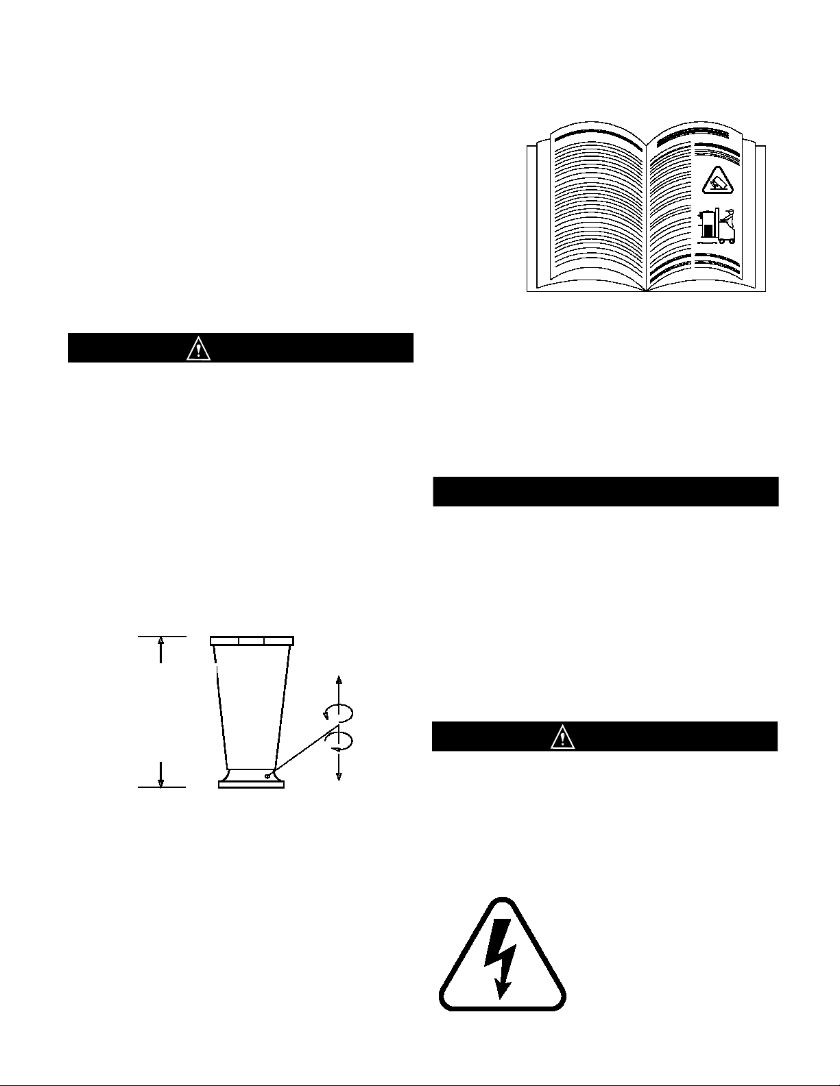
Fig. 1Leg Installation ................................................................................................................................................ 1
Fig. 2ontrol Switch ................................................................................................................................................. 2
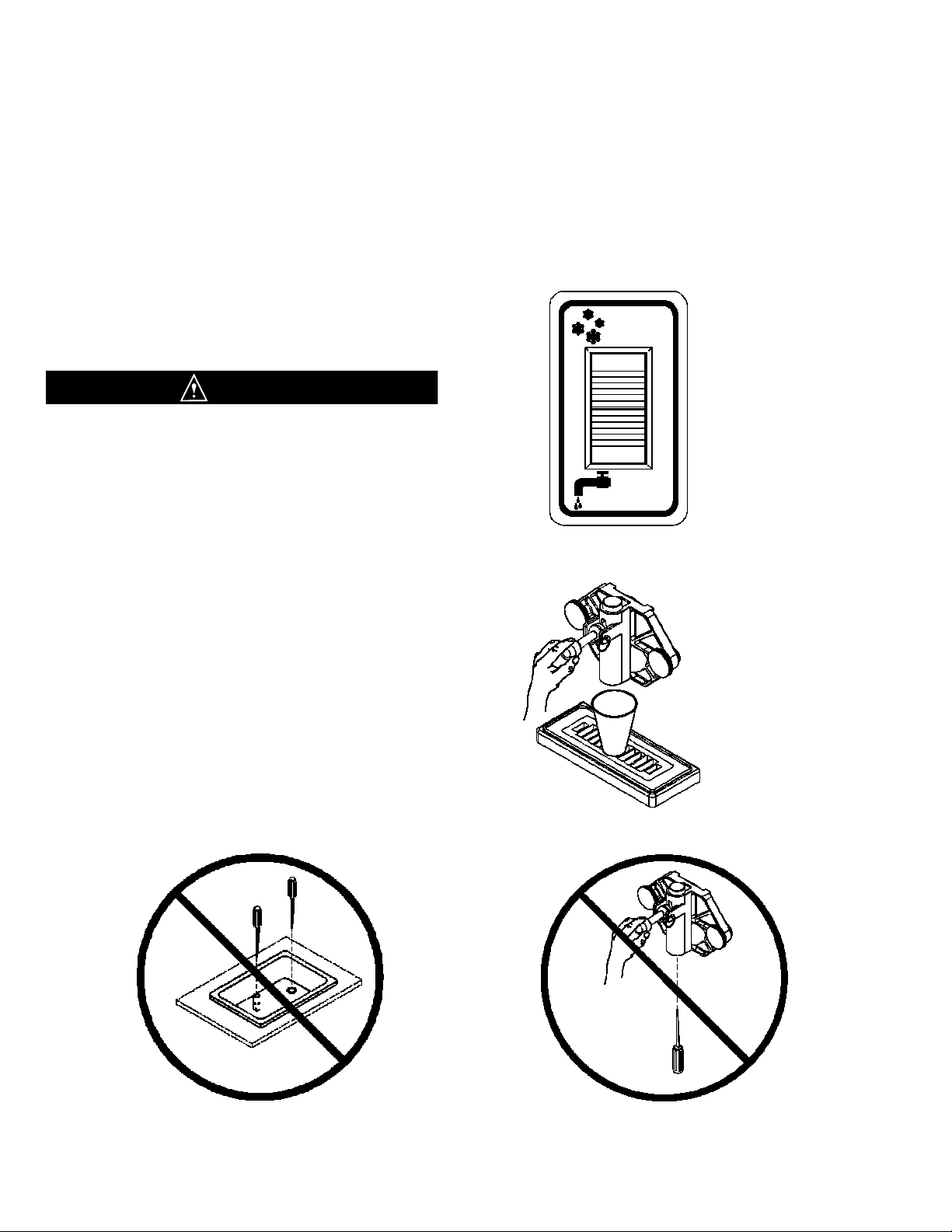
Fig. 3Do Not Insert Objects!..................................................................................................................................... 3
Fig. 4ontrol Switch ................................................................................................................................................. 3
Fig. 5Dispensing Product ......................................................................................................................................... 3
Fig. 6ontrol Switch ................................................................................................................................................. 4
Fig. 7Dispensing Product ......................................................................................................................................... 4
Fig. 8Front Plate Assembly ...................................................................................................................................... 4
Fig. 9O-Ring Removal.............................................................................................................................................. 4
Fig. 10 Dasher Assembly ............................................................................................................................................ 5
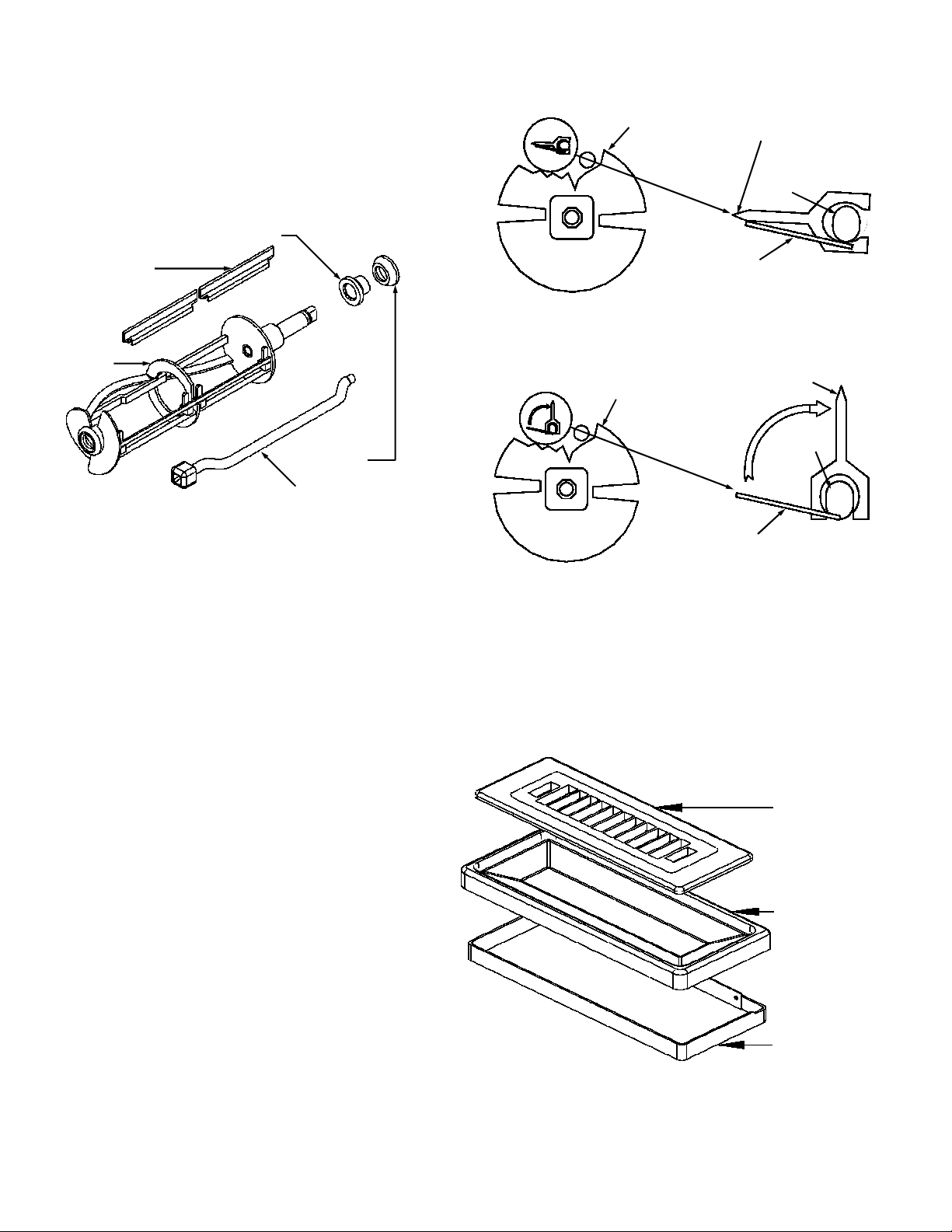
Fig. 11 Scraper Blade Removal .................................................................................................................................. 5
Fig. 12 Drip Tray Assembly......................................................................................................................................... 5
Fig. 13 leaning ALL Ports and Holes........................................................................................................................ 6
Fig. 14 Dasher Lubrication .......................................................................................................................................... 7
Fig. 15 Dasher Assembly ............................................................................................................................................ 7
Fig. 16 Scraper Blade Installation ............................................................................................................................... 8
Fig. 17 Scraper Blade Installation ............................................................................................................................... 8
Fig. 18 Scraper Blade Wear Mark............................................................................................................................... 8
Fig. 19 Dasher Installation .......................................................................................................................................... 8
Fig. 20 Dasher Installation .......................................................................................................................................... 8
Fig. 21 Dasher with Blade (Front View) ...................................................................................................................... 9
Fig. 22 Spigot Plunger Lubrication.............................................................................................................................. 9
Fig. 23 Front Plate Assembly...................................................................................................................................... 9
Fig. 24 Drip Tray Assembly......................................................................................................................................... 9
Fig. 25 ontrol Switch ............................................................................................................................................... 10
Fig. 26 Do Not Insert Objects!................................................................................................................................... 10
Fig. 27 Dispensing Product ....................................................................................................................................... 11
Fig. 28 MIXOUT Light ............................................................................................................................................... 11
Fig. 29 Water-ooled ondenser Valve ................................................................................................................... 12
Fig. 30 Wiring Box..................................................................................................................................................... 13
Fig. 31 Electronic onsistency ontrol ..................................................................................................................... 13
Fig. 32 Scraper Blade Wear Mark............................................................................................................................. 14
Fig. 33 lean Sharp ondenser Fins........................................................................................................................ 14

INTRODU TION &
4. Electrical and refrigeration specifications are
located on the data plate on the rear of the individual
machines. onsult local authorities for information
regarding plumbing and electrical codes in the area.
Note: All SaniServ machines should have their
own dedicated circuits whether they are cord
connected plug-in devices or hard wired units.
ALWAYS CHECK ELECTR CAL SPEC FlCAT ONS
ON THE DATA PLATE OF THE MACH NE. DATA
PLATE SPEC F CAT ONS ALWAYS SUPERSEDE
ELECTR CAL NFORMAT ON N TH S MANUAL.
5. The water line connections on water-cooled
machines are located on the back side of the machine.
The N/OUT lines are clearly marked and have 1/4”
male pipe threads fitted with a 3/4” garden hose fitting.
Note: These water lines are installed on water-cooled
machines only.
FA LURE TO PROV DE FOR PROPER EARTH
GROUND ACCORD NG TO LOCAL ELECTR CAL
CODES COULD RESULT N SER OUS ELECTR CAL
SHOCK OR DEATH. DO NOT USE EXTENS ON
CORDS. NSTALL THE PROPER S ZE W RE FOR
THE REQU RED MACH NE AMPS. BE CERTA N TO
OBSERVE LOCAL CODES N SELECT NG W RE OR
CORD S ZE AND TYPE.
DO NOT TURN MACH NE ON
UNT L THE NSTALLER’S
PRE-OPERAT ONAL
CHECK SECT ON S
COMPLETE.
Introduction
Installation
WARN NG
MPORTANT
This manual provides a general system description of the SaniServ Frozen Beverage Dispensers. It has been prepared
to assist in the training of personnel on the proper installation, operation, and maintenance of the machines.
Read and fully understand the instructions in this manual before attempting to
install, operate, or perform routine maintenance on the machines.
The following sections of the manual must be performed in sequence:
1. Installation 4. Assembly & Lubrication
2. Installer's Preoperational heck 5. Sanitizing & Operation
3. Disassembly & leaning 6. onsistency Adjustment
PAGE 1
ALWAYS USE A SUFF C ENT NUMBER OF PEOPLE
OR MECHAN CAL L FT NG EQU PMENT TO
PROTECT ALL PERSONNEL FROM PERSONAL
NJURY DUR NG THE REMA N NG STEPS.
1. Raise the machine to install the four legs packed in
the mix pan or the four casters packed in a box on the
skid or on the front mounted drip tray. Be certain all
four are tight! Thread lock is suggested.
2. arefully lower the machine to the floor and place it
where it will be installed.
3. Level the unit by turning the bottom part of each leg
clockwise or counterclockwise (Fig. 1). The machine
MUST be level to operate properly.
THESE UN TS MUST NOT BE
OPERATED W THOUT
LEGS NSTALLED OTHERW SE BOTTOM
A RFLOW TO THE CONDENSER W LL BE
RESTR CTED.
A M N MUM 6” (152 MM) CLEARANCE MUST
BE MA NTA NED AT THE REAR AND S DES
OF THE MACH NE FOR ADEQUATE
VENT LAT ON.
Fig. 1
Minimum
Clearance
4”(102 mm) for
Counter Top
Models and
6”(152 mm) for
Floor Models
WARN NG

Installer’s Preoperational heck
THE FOLLOW NG TEMS MUST BE PERFORMED BEFORE ATTEMPT NG TO OPERATE THE EQU PMENT:
INSTALLERS PREOPERATIONAL HE K PAGE 2
Fig. 2
Control Switch
AUTO
CLEANOUT
O
F
F
O
F
F
1. Make certain that proper electrical connections have
been made. Plug power cord into power outlet.
2. Set each control switch (Fig. 2) to the “CLEANOUT”
position momentarily to verify the direction of rotation of
the dasher. Looking at the front of the machine, the
dasher should rotate counter-clockwise.
3. Set each control switch to the “OFF” position.
In the event the dasher turns clockwise, STOP and
do not proceed any further. On three-phase units,
reverse the polarity.
WARN NG
UNDER NO C RCUMSTANCES SHOULD THE UN T
BE OPERATED N THE “AUTO” POS T ON FOR MORE
THAN THREE M NUTES W TH EMPTY FREEZ NG
CYL NDERS . DO NG SO W LL RESULT N DAMAGE
TO THE MACH NE.
CAUT ON
This machine was designed
to produce frozen slush
beverages only.
Do NOT attempt to operate
this machine with softserve
or shake type product mix.
Damage to the machine may
occur and warranty will be
void.
MPORTANT
A M N MUM OF 6” (152 MM)
CLEARANCE MUST BE
MA NTA NED AT THE REAR
AND S DES OF THE MACH NE
FOR ADEQUATE VENT LAT ON.
MPORTANT

Emptying Machine
Prior to the disassembly and cleaning of parts, the
machine must be emptied of product. Use the following
procedures (Steps 1 through 3). If this is first time
operation, disregard these steps.
DO NOT NSERT ANY OBJECTS OR TOOLS (F G. 3)
NTO THE M X NLET HOLE, RESTR CTOR TUBE
HOLE, OR FRONT PLATE D SPENS NG HOLE WH LE
THE MACH NE S RUNN NG. DAMAGE TO THE
MACH NE OR PERSONAL NJURY MAY RESULT
1. Set the control switch (Fig. 4) to the “CLEANOUT”
position and dispense all product from the freezing
cylinder by pulling downward on the spigot handle
(Fig. 5) to empty the machine.
2. Set the control switch (Fig. 4) to the “OFF” (center)
position. lose the spigot handle (Fig. 5) before
proceeding to cleaning.
CONSULT YOUR LOCAL HEALTH AGENCY FOR LOCAL CLEAN NG AND SAN T Z NG REQU REMENTS.
This unit does not come pre-sanitized from the factory. Before serving product, the dispenser must be disassembled,
cleaned, lubricated, and sanitized. Please be aware that these instructions are general guidelines. leaning and sanitizing
procedures must conform to local Health Authority requirements.
DISASSEMBLY and LEANING
Fig. 5
Dispensing Product
Fig. 4
Control Switch
Disassembly and leaning
PAGE 3
AUTO
CLEANOUT
O
F
F
O
F
F
Fig. 3
Do Not nsert Objects or Tools
CAUT ON

DISASSEMBLY and LEANING
Disassembly and Cleaning Procedure
1. Fill the machine with cold water and set each control
switch (Fig. 6) to the “CLEANOUT” position. DO NOT
use hot water which could damage the machine. Let the
machine agitate 1 to 2 minutes, then drain the water by
pulling downward on the spigot handle (Fig. 7). Repeat
the above procedure as necessary to make certain all
product is removed from the machine. After the machine
is empty, set the control switch to the “OFF” position.
2. Prepare a suitable detergent and water solution at a
temperature of approximately 125°F. (52°.) to 130°F.
(55°.). For best cleaning results select a concentrated
anti-bacterial dishwashing detergent containing
biodegradable anionic and nonionic surfactants. Avoid
detergents containing phosphates. DO NOT use an
abrasive detergent on any part of the dispenser.
DO NOT USE HOT WATER.
DO NG SO MAY DAMAGE THE MACH NE.
3. Make certain that the machine is “OFF”. Fill the mix
pan with the cleaning solution. lean the mix pan
thoroughly with a brush as the solution drains into the
freezing cylinder(s). lean the mix inlet tube(s) and the
restrictor tube holes with the brush provided.
4. Set the control switch (Fig. 6) to the “CLEANOUT”
position and agitate for approximately 1 to 2 minutes and
then drain the water by pulling down on the spigot handle
(Fig. 7). After the unit is empty, set each control switch to
the “OFF” position.
DO NOT USE ANY TOOLS OR SHARP OBJECTS TO
REMOVE ANY O-R NGS FROM TH S MACH NE.
SHARP OBJECTS W LL DAMAGE THE O-R NGS.
5. Remove the front plate by turning the black plastic
knobs in a counterclockwise direction (Fig. 8).
Disassemble the front plate in the following manner:
a. Remove the faspin and spigot handle.
b. Remove the front plate o-ring.
c. With the spigot handle removed, push the spigot
plunger out the top of the front plate and remove all
lubricant from the spigot plunger.
d. Remove the o-rings from the spigot plunger by
grasping the part with one hand and with a dry
cloth in the other hand, squeeze the o-ring upward.
When a loop is formed, grasp the o-ring with the
other hand and roll it out of its groove and off the
spigot plunger (Fig. 9).
Fig. 7
Dispensing Product
Spigot Plunger
Faspin
Spigot
Handle
Front Plate
Front Plate O-ring
DO NOT LUBR CATE
Spigot Plunger
O-rings
Front Plate
Knobs
Fig. 6
Control Switch
Fig. 8
Front Plate Assembly
Fig. 9
O-Ring Removal
PAGE 4
AUTO
CLEANOUT
O
F
F
O
F
F
CAUT ON
CAUT ON

9. Remove the dasher assembly (Fig. 10) being careful
not to damage the scraper blades, then disassemble
in the following manner:
a. Remove and take apart the rear seal assembly.
b. Remove the stator rod from the dasher.
c. Remove the blades from the dasher (Fig. 10) by
first rotating blade upward (Fig. 11) and then
unsnapping one end from the support rod.
BLADES MUST BE REMOVED FOR CLEAN NG
10. Remove the mix pan lid, drip tray and drip tray
Dasher Front
View Scraper Blade
Blade Support
Tab
Support
Rod
Blade Support
Tab
Support
Rod
Dasher Front
View
Scraper Blade
Fig. 11
Scraper Blade Removal
DISASSEMBLY and LEANING
PAGE 5
Fig. 12
Drip Tray Assembly
Drip Tray nsert
Drip Tray
Drip Tray Support
Remains Attached
To Machine Front
Fig. 10
Dasher Assembly
Scraper Blade
Rear Seal
Rear Bearing
Dasher
Stator Rod

12. Place all parts in a three partition sink filled with the
following solutions:
a. In one partition, detergent solution diluted to the
manufacturer’s suggested concentration for use.
b. In a second partition, clear rinse water.
c. In a third partition, sanitizing rinse solution which
will produce a 200 parts per million (PPM) hlorine
residual or whatever hlorine residual is required by
your Local Health Authority.
13. Use the brushes to clean all holes and ports in the
parts (Fig. 13).
DO NOT use an abrasive detergent
14. After thoroughly washing the parts in the detergent
solution, rinse them in the clear rinse water. Place the
parts in the sanitizing solution for at least five minutes or
whatever your Local Health Authority requires, and then
air dry the parts before for assembly and lubrication.
DO NOT ALLOW THE PARTS TO SOAK N
SAN T ZER FOR SEVERAL HOURS.
DO NOT W PE THE PARTS DRY - A R DRY ONLY.
15. The remainder of the machine including the mix pan
and freezing cylinder must be cleaned in place using a
mild detergent solution followed by a clear rinse. lean
the exterior with a damp cloth.
DO NOT use an abrasive cleaner on the exterior of the
machine or on any of the panels (guards).
WHEN CLEAN NG THE MACH NE, DO NOT ALLOW
EXCESS VE AMOUNTS OF WATER AROUND ANY
ELECTR CALLY OPERATED COMPONENTS OF THE
MACH NE. ELECTR CAL SHOCK OR DAMAGE TO
THE MACH NE MAY RESULT.
11. For best cleaning results select a concentrated
anti-bacterial dishwashing detergent containing
biodegradable anionic and nonionic surfactants.
NOTE: Avoid detergents containing phosphates.
WEAR SAFETY GLASSES - DO NOT SPLASH
DETERGENT SOLUT ON
N EYES
Be certain to follow the
manufacturer’s mixing
instructions when adding
the dishwashing detergent
concentrate to water.
DISASSEMBLY and LEANING
CAUT ON
PAGE 6
Fig. 13
Clean ALL Holes and Ports
with Brushes
CAUT ON
CAUT ON
CAUT ON
WARN NG

1. Lubricate and assemble the dasher assembly in the
following manner:
a. Apply a generous amount of lubricant to the
shoulder of the dasher and the area of the shaft
where the white plastic portion of the assembled
rear seal contacts the shaft (Fig. 14). This is easily
performed by running a 1/4” (6 mm) bead of
lubricant around the shoulder of the dasher.
b. Lubricate the two areas of the stator rod (Fig. 14)
and slide the stator rod into the dasher (Fig. 15).
Make certain that the end of the stator rod is
inserted into the hole at the rear of the dasher.
c. Assemble and install the rear seal with the rubber
portion toward the rear of the freezing cylinder as
indicated in Fig. 15.
DO NOT LUBR CATE THE RUBBER PORT ON OF
THE REAR SEAL. LUBR CAT ON ON THE REAR
SEAL W LL DAMAGE THE MACH NE.
Use a food grade lubricant* ONLY. SaniServ part number 1150 is recommended and is available from the factory or your
local authorized SaniServ dealer or distributor. Lubrication must be performed daily.
* The SaniServ recommended product is a colorless to white, odorless, tasteless food contact lubricant accepted by the
United States Food and Drug Administration (FDA) with a USDA rating of H1 and certified for food contact by NSF
International. Its useful temperature range is -15°F - 210°F (-26° - 99°) with a melt point of 93° using ASTM D566
and a Saybolt viscosity of 55 at 210°F (99°) when measured using ASTM D445
ASSEMBLY and LUBRI ATION
Fig. 14
Stator Rod and Dasher Lubrication
PAGE 7
Assembly and Lubrication
Lubricate
Shaded
Areas
Scraper
Blade
Dasher
Stator Rod
Rear Bearing
Rear Seal
Fig. 15
Dasher Assembly
CAUT ON

d. Install the scraper blades onto the dasher
assembly by holding the blades perpendicular to
the tabs (Fig. 16) and then snapping them over the
flat area of the support rod. Then rotate the blades
downward in a counterclockwise direction as
viewed from the front of the dasher (Fig. 17). BE
CERTA N THAT THE SCRAPER BLADES REST
UPON THE DASHER TABS.
Note: Reverse the blades at each cleaning to maintain
sharpness. In addition, the blades are equipped
with a wear mark (Fig. 18). When the blade is
worn to this wear mark, it must be replaced.
Blade Support
Tab
Support Rod
Dasher Front View
Scraper Blade
Dasher Front
View
Blade Support
Tab Support Rod
Scraper Blade
Rotate Down
Counter
Clockwise
Scraper Blade Wear Mark
End
View
Side
View
ASSEMBLY and LUBRI ATION PAGE 8
Fig. 17
Scraper Blade nstallation
Fig. 16
Scraper Blade nstallation
Fig. 18
Scraper Blade Wear Mark
e. Insert the dasher assembly into the freezing
cylinder as far as possible (Fig. 19) being careful
not to damage the scraper blades. Damage will
occur to the scraper blades and the dispenser will
not operate properly if the scraper blades are
installed facing in a clockwise direction (Fig. 20).
Note: The stator rod has been deleted from Fig. 19 and
Fig. 20 for clarity only. The stator rod must be installed
for proper machine operation.
f. While maintaining force against the dasher, rotate it
slowly until the tongue of the dasher engages the
groove in the drive system at the rear of the
cylinder. The outer most portion of the dasher
should be recessed approximately 1/4” (6 mm) to
3/8” (10 mm) inside the freezing cylinder. No part
of the dasher should extend outside the cylinder.
Scraper blades should be visible, extending
approximately 1/8” (3 mm) beyond the dasher
(Fig. 21).
CORRECT
Blades
Resting On Tabs
Blades Pointing n A
Counterclockwise
Direction
Blades Should
Rest On Tabs
Blades Should Not Point
n A Clockwise Direction
NCORRECT
Fig. 19
Dasher nstallation
Fig. 20
Dasher nstallation

2. Lubricate and assemble the front plate assembly in
the following manner:
a. Install the two o-rings on the spigot plunger by
rolling them onto the plunger. Seat the o-rings in
the grooves. Be certain that they are not twisted.
Smooth the lubricant into the grooves and over
the sides of the plunger assembly (Fig. 22).
b. Slide the lubricated spigot plunger into the front
plate (Fig. 23) making certain that the spigot handle
slot is aligned to the front.
. Insert the spigot handle and secure with the faspin.
d. Install the front plate o-ring.
DO NOT LUBR CATE THE FRONT PLATE O-R NG
PAGE 9
Fig. 21
Dasher with Blade (Front View)
ASSEMBLY and LUBRI ATION
Approximately 1/8 inch
Exposed
Fig. 22
Spigot Plunger Lubrication
Lubricate Shaded Area
e. Secure the front plate assembly with the two
plastic knobs. Simultaneously, turn the knobs in a
clockwise direction. Tighten the knobs evenly.
DO NOT tighten one knob all the way down and
then the other. Doing so may result in front plate
breakage. Only moderate force is required.
DO NOT over tighten. lose the spigot plunger.
3. Install the drip tray and drip tray insert (Fig. 24).
4. Proceed to the “Sanitizing” section of this manual.
Drip Tray Support
Remains Attached
To Machine Front
Drip Tray
Fig. 24
Drip Tray
Assembly
Drip Tray nsert
Spigot Plunger
Faspin
Spigot
Handle
Front Plate
Front Plate O-ring
DO NOT LUBR CATE
Spigot Plunger
O-rings
Front Plate
Knobs
Fig. 23
Front Plate Assembly

1. First, wash hands with a
suitable antibacterial hand soap.
For best results select a
concentrated anti-bacterial hand
soap containing biodegradable
anionic and nonionic surfactants.
2. Prepare approximately 2 to 3
gallons (8 to 12 liters) of sanitizing
solution equivalent to 200 ppm
chlorine residual or the residual
required by your local health
agency.
3. arefully pour the solution
into the mix pan.
4. Using a sanitary brush, wipe
the solution onto the sides of
the mix pan, over the mixout
probe in the bottom of the mix
pan, and the underside of the
mix pan lid.
5. Set the control switch
(Fig. 25) to the “CLEANOUT”
position and let the unit agitate
for approximately three to five
minutes.
NOTE: DO NOT set the control switch to the “AUTO”
position. Doing so would freeze the sanitizing solution
and may result in damage to the machine.
DO NOT NSERT ANY TOOLS OR OBJECTS NTO
THE M X NLET HOLE, RESTR CTOR TUBE HOLE,
OR THE D SPENS NG HOLE N THE FRONT PLATE.
DAMAGE TO THE MACH NE OR PERSONAL
NJURY MAY RESULT (F G. 26)
6. Set the control switch to the “OFF” position and
drain the solution from the machine. Proceed directly
to the “Operation” section of this manual.
DO NOT R NSE OUT THE MACH NE.
DO NOT ALLOW SAN T Z NG SOLUT ON TO
REMA N N THE MACH NE FOR SEVERAL HOURS.
DO NG SO COULD DAMAGE THE MACH NE.
Prior to operation, the machine must be sanitized. The unit must have already been cleaned and lubricated.
Note: Sanitize immediately before use, not several hours before or the previous evening.
SANITIZING
Fig. 25
Control Switch
Sanitizing
PAGE 10
AUTO
CLEANOUT
O
F
F
O
F
F
Fig. 26
Do Not nsert Objects or Tools
WARN NG
WARN NG

Always start with a cleaned and sanitized dispenser as per previous instructions. Use only fresh mix when filling the
units. Following these instructions is critical to the maximum operating efficiency of the machine.
1. Set ontrol Switch to the “OFF” position.
2. Place a 16 oz. cup under the spigot and open the
spigot handle. Pour approximately one quart of fresh
product mix into the mix
pan. (This will chase the
sanitizing solution from
the mix pan and freezing
cylinder.) lose the
spigot handle when the
sanitizer is purged from
the system.
3. Fill the mix pan with
chilled, properly mixed
product. Keep the mix
level in the mix pan at
least one inch
(25 mm) deep at all
times to avoid starving
the freezing cylinder. A
M XOUT light (Fig. 28) located on the front of the
machine is activated when the mix solution drops to a
potentially damaging level.
4 Set the control switch to the “AUTO” position to start
the machine.
5. Allow the compressor to cycle 3 or 4 times
dispensing a sample of the product after each cycle to
check for consistency. If the machine is not dispensing
the product at the desired consistency after four full
cycles, refer to the onsistency ontrol Section of this
manual. Initial pull-down time is 20-30 minutes, but it
may vary due to product and ambient conditions.
6. Replace the mix pan lid and always operate the
machine with the lid on the mix pan reservoir.
Note: SaniServ dispensers are designed to run frozen
beverage products having a Brix (sugar content) range
of 12.5 to 14 with a dispense temperature of 26°F to 28
°F (-3.3° to -2.2°).
Brix reading is taken by placing a small sample of
normally diluted concentrate on the viewer of a
refractometer. If a refractometer is not available,
contact the mix supplier.
Do not use a mix with a Brix reading of less than
12.5. Doing so may result in serious damage to the
machine.
If the Brix reading is above 14.0 or the alcohol content
is too high, the freezing point of the solution may be too
low to form slush.
DO NOT ATTEMPT TO MAKE FROZEN BEVERAGE
US NG ART F C ALLY SWEETENED PRODUCT.
OPERATION
Fig. 27
Dispensing Product
Operation (Filling and Starting)
consistency, and the compressor will cycle on if it is
needed. If the liquid level sensor detects a low level
condition, it will flash the “M XOUT” light and activate
the beeper for three minutes or until the mix pan is filled
to satisfy the mix level probe. If the beeper is activated
for more than three minutes, the light will begin to glow
continuously, the beeping tone will slow down, and the
machine will no longer dispense product.
Control Switch Positions
“CLEANOUT” Position: The dasher motor operates
continuously and the compressor will not come on.
The mix out level sensor will turn on the “M XOUT”
light (Fig. 28) but will not activate the beeper.
“AUTO” Position: The dasher motor operates
continuously. Upon machine start up the compressor
will run until proper product consistency is reached.
Then the compressor will shut off. Approximately every
10 minutes thereafter, the machine will test the product
WARN NG
PAGE 11
Fig. 28
M XOUT Light

Helpful Hints
HELPFUL HINTS
Front Plate: This component is the plastic device from
which the product is dispensed. It is designed and
manufactured for strength and durability. However,
through improper use, the front plate can be damaged.
Use the following information for proper care:
a. Do not over tighten the knobs.
b. Always tighten knobs evenly. Do not attempt to
turn one knob all the way down and then one of
the other three knobs. Doing so will bind the front
plate and could result in breakage.
c. Improper installation of the stator rods can cause
breakage. The stator rods must be properly
seated in the dasher before installing the front
plate. If the stator rods are improperly installed,
subsequent tightening of the knobs will break the
front plate.
d. DO NOT attempt to wash the front plate or any
other components in a dishwasher.
Mix Out Light: When the mix out light comes on, the
mix pan is low on mix. The mix pan must be filled with
fresh product mix immediately to prevent air from
entering the freezing cylinder starving the machine and
causing freeze-up and vibration. If this condition occurs,
set the selector switch to the “OFF” position. Add mix
to the low mix pan until the freezing cylinder stops
bubbling. Return the control switch to the “AUTO”
position.
Filling: Always fill the machine with fresh product at the
start of each day.
Drip Tray: This should be removed daily and cleaned
to remove residue.
Mix Pan Lid: Be certain to leave the lid in place on top
of the machine to prevent any foreign materials from
contaminating the mix.
Mixing: Make certain that the product mix is prepared
according to label instructions.
Sanitizing: Do not soak plastic parts in sanitizer
overnight. Doing so can cause the plastic parts to
become brittle and lead to premature failure.
Fig. 29
Water-Cooled
Condenser Valve
PAGE 12
Winter Storage: To protect the unit during seasonal
shut-down, it is important that the dispenser be stored
in the proper manner. Use the following procedures:
1. Turn off ALL power to the machine.
2. Wash all parts that come in contact with the mix
with a warm mild detergent solution. Rinse in clear
water and dry parts thoroughly.
3. Store the loose parts such as the mix pan
components, front plate parts, and the dasher
assembly parts outside of the machine.
4. Do not lay heavy objects on the plastic or rubber
parts.
5. over the machine and all loose parts to protect
them from dust or other contaminants while in
storage. Place the machine in a dry location.
6. On water-cooled units, disconnect the water
lines. Use compressed air to blow out all
remaining water in the condenser. nsert a
screwdriver (Fig. 29) to open the water valve.
Note: Failure to purge the machine of water
can result in severe damage to the cooling
system. This task should be performed by a
qualified service technician.
Closed Hours/Shut-Down: If the machine is turned
off during closed hours, to resume operation:
1. Set the control switch to the "CLEANOUT" position.
2. Dispense two quarts (2 liters) of product into a
sanitized pitcher and pour it back into the mix pan.
Doing so serves as a mixing process to eliminate any
overnight separation.

onsistency Adjustment
onsistency adjustment is done by adjusting the
potentiometer on the electronic control board (E B).
The E B is located behind the front wiring box cover
above the front dispensing plate.
1. Remove two Phillips screws on the underneath
side of the wiring box cover. The E B is located
on the left side of the wiring box as show in Fig. 30.
2. Locate the black potentiometer labeled
HARDNESS as shown in Fig. 31. By turning the
potentiometer to the right (clockwise) it will
increase the thickness and lower the product
temperature. Turning the potentiometer to the left
(counter clockwise) will decrease the thickness and
raise the temperature.
3. Reinstall the wiring box cover and reconnect the
power.
4. Run the unit with product and allow the
refrigeration system to cycle TWO times.
5. Draw product from the machine and check for
desired consistency.
6. Repeat procedure if required.
NOTE: ONLY TURN THE POTENT OMETER N
SMALL NCREAMENTS.
PAGE 13 ONSISTEN Y ADJUSTMENT
Fig. 31
Electronic Consistency
Control
CAUT ON
BEFORE PROCEED NG
D SCONNECT THE POWER
Electronic onsistency ontrol
Fig. 30
Wiring Box
Adjustments to the Electronic onsistency ontrol System should only be made by a certified SaniServ
service technician. DO NOT attempt to make adjustments or repairs on the machine.
This machine is designed with an electronic control board to manufacture Frozen Slush Beverage On-
ly! Do not attempt to operate the machine with soft serve and or shake type products. Operating
unit with soft serve or shake products will damage the machine and factory warranty will be voided.
DO NOT ADJUST THE MACH NE!
mproper consistency may be due to improperly mixed product
This equipment has been tested at the factory with slush product and has been shipped with FA TORY
PRE-SETS. Non-Alcoholic beverage temperature will range from 25-28 degrees. Alcoholic beverage
temperature will range from 17-22 degrees. If you feel a consistency adjustment is needed, check the
temperature of the dispensed product before making an adjustment. If your product is within these tem-
perature ranges and the consistency is incorrect, you may have improperly mixed product.
ADJUSTING THE MA HINE TO OMPENSATE FOR IMPROPERLY MIXED PRODU T MAY AUSE
PRE-MATURE OMPONENT FAILURE AND MAY VOID WARRANTY.
CAUT ON !

Routine Maintenance (Trained Service Technician)
Routine Maintenance (Owner-Operator)
ROUTINE MAINTENAN E PAGE 14
Scraper Blade Wear Mark
End
View
Side
View
Fig. 32
Scraper Blade Wear Mark
CONDENSER F NS ARE VERY SHARP
USE EXTREME CAUT ON WHEN CLEAN NG
Quarterly: Thoroughly clean the condenser fins on all
air-cooled machines. Remove all lint and dust with a
vacuum cleaner or compressed air (Fig. 33) to clean
fins. A dirty condenser greatly reduces refrigeration
capacity and efficiency. When using compressed air,
place a damp cloth on the opposite side of the
condenser to catch the flying dirt or lint.
Annually: heck the belts for signs of wear or cracking.
Remove panels and clean all parts inside of the machine
including the base, side panels, fan blades, condensers,
etc.
D SCONNECT THE MACH NE FROM TS POWER
SOURCE(S) BEFORE PERFORM NG ANY ROUT NE
MA NTENANCE. PERSONAL NJURY OR DAMAGE
TO THE MACH NE COULD RESULT F TH S
PRACT CE S NOT OBSERVED.
Daily: Inspect the machine for signs of product leaks
past seals and gaskets. If proper assembly does not
stop leaks around gaskets or seals, check for improper
lubrication and worn or damaged parts. Replace parts
as needed.
Periodically: Inspect the scraper blades (Fig. 32) to
see that they are straight and sharp. If worn, damaged
or warped, the blades will not scrape the cylinder walls
correctly and the freezing capacity will be reduced.
lean the drip chute assembly with warm water and
detergent solution.
Fig. 33
Clean Sharp Condenser Fins
WARN NG
WARN NG

PAGE 15
TROUBLESHOOTING GUIDE
This manual suits for next models
5
Other SaniServ Beverage Dispenser manuals
Popular Beverage Dispenser manuals by other brands

Welbilt
Welbilt Multiplex FreshBlender Service manual

MICROMATIC
MICROMATIC PRO-LINE WINE MDD58W Series Installation, use & maintenance guide

Cornelius
Cornelius PRISM owner's manual

Bunn
Bunn IGV 699 Use & care information

Silver King
Silver King SKBD110P Technical manual and replacement parts list

Cuisinart
Cuisinart SMS-201 Series Instruction booklet