Table of Contents
Introduction and Installation ............................................................................................................................................... 1
Installer’s Preoperational Check ........................................................................................................................................ 2
Disassembly and Cleaning................................................................................................................................................. 3
Assembly and Lubrication (WB700, WB700-2).................................................................................................................. 7
Assembly and Lubrication (WB7110)............................................................................................................................... 10
Sanitizing ......................................................................................................................................................................... 12
Operation (Filling and Starting) ........................................................................................................................................ 14
Helpful Hints..................................................................................................................................................................... 15
Consistency Adjustment................................................................................................................................................... 16
Routine Maintenance ....................................................................................................................................................... 17
Troubleshooting Guide..................................................................................................................................................... 18
Troubleshooting Glossary ................................................................................................................................................ 19
Service Record................................................................................................................................................................. 20
TABLE OF CONTENTS
iii
Illustrations
Fig. 1 Leg Installation................................................................................................................................................ 1
Fig. 2 Drip Tray Bracket Installation ......................................................................................................................... 1
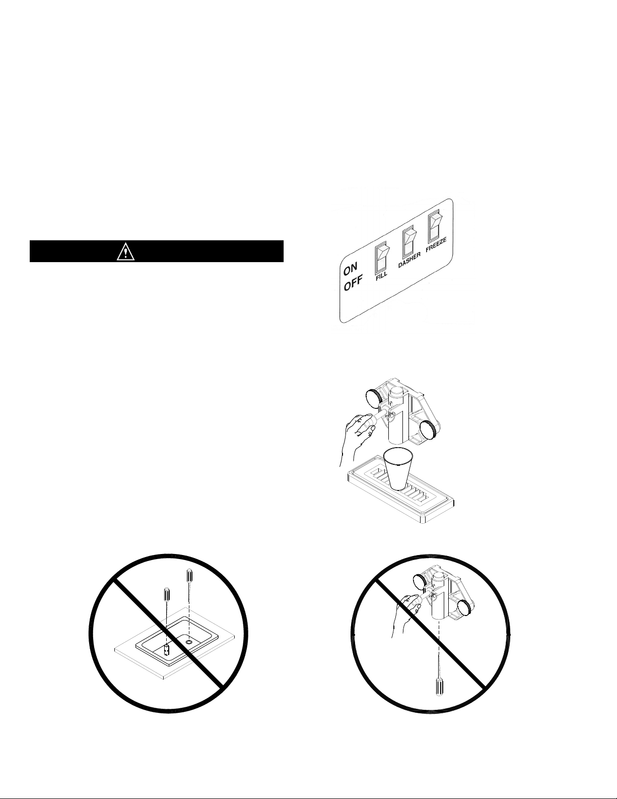
Fig. 3 Control Switch................................................................................................................................................. 2
Fig. 4 Do Not Insert Objects! .................................................................................................................................... 3
Fig. 5 Control Switch................................................................................................................................................. 3
Fig. 6 Dispensing Product......................................................................................................................................... 3
Fig. 7 Control Switch................................................................................................................................................. 4
Fig. 8 Dispensing Product......................................................................................................................................... 4
Fig. 9 Front Plate Assembly (WB700, WB700-2) ..................................................................................................... 4
Fig. 10 O-Ring Removal ............................................................................................................................................. 4
Fig. 11 Dasher Assembly (WB700, WB700-2) ........................................................................................................... 5
Fig. 12 Dasher Assembly (WB7110) .......................................................................................................................... 5
Fig. 13 Scraper Blade Removal.................................................................................................................................. 5
Fig. 14 Drip Tray Assembly ........................................................................................................................................ 5
Fig. 15 Clean ALL Ports and Holes ............................................................................................................................ 6
Fig. 16 Stator Rod and Dasher Lubrication (WB700, WB700-2)................................................................................ 7
Fig. 17 Dasher Assembly (WB700, WB700-2) ........................................................................................................... 7
Fig. 18 Scraper Blade Installation............................................................................................................................... 8
Fig. 19 Scraper Blade Installation............................................................................................................................... 8
Fig. 20 Scraper Blade Wear Mark .............................................................................................................................. 8
Fig. 21 Dasher Installation .......................................................................................................................................... 8
Fig. 22 Dasher Installation .......................................................................................................................................... 8
Fig. 23 Dasher With Blade (Front View) ..................................................................................................................... 9
Fig. 24 Spigot Plunger Lubrication ............................................................................................................................. 9
Fig. 25 Front Plate Assembly (WB700, WB700-2) ..................................................................................................... 9
Fig. 26 Drip Tray Assembly ........................................................................................................................................ 9
Fig. 27 Dasher Support and Dasher Lubrication ...................................................................................................... 10
Fig. 28 Dasher Assembly.......................................................................................................................................... 10
Fig. 29 Dasher Installation ........................................................................................................................................ 10
Fig. 30 Front Plate Assembly (WB7110) .................................................................................................................. 11
Fig. 31 Spigot Plunger Lubrication ........................................................................................................................... 11
Fig. 32 Drip Tray Assembly ...................................................................................................................................... 11
Fig. 33 Control Switch............................................................................................................................................... 12
Fig. 34 Do Not Insert Objects! .................................................................................................................................. 12
Fig. 35 Optional Drink Spinner.................................................................................................................................. 13
Fig. 36 Dispensing Product....................................................................................................................................... 14
Fig. 37 MIXOUT Light ............................................................................................................................................... 14
Fig. 38 Wiring Box .................................................................................................................................................... 16
Fig. 39 Hardness Control.......................................................................................................................................... 16
Fig. 40 Scraper Blade Wear Mark ............................................................................................................................ 17