SaniServ A7081HEP User manual

“Reliability from the team that Serves the Best”
SaniServ P.O. Box 1089 Mooresville, Indiana 46158
Operation Manual
Pressurized Frozen Beverage Dispenser
Model A7081HEP
SaniServ®
An AFFINIS GROUP Company


Distributor Name: _______________________________________________________
Address: ______________________________________________________________
Phone: ________________________________________________________________
Date of Installation: _____________________________________________________
Model Number: _________________________________________________________
Serial Number: _________________________________________________________
Installer/Service Technician: _____________________________________________
SERVICE: Always contact your SaniServ dealer or distributor for service questions or service
agency referral. If your SaniServ dealer or distributor cannot satisfy your service requirements,
he is authorized to contact the factory for resolution.
Note: It is the Owner’s responsibility to maintain the Service Record located on the inside rear
cover of this manual. An accurate record of service performed can greatly expedite
troubleshooting of problems and significantly reduce repair costs.
PARTS: Always order parts from your SaniServ dealer or distributor. When ordering
replacement parts, specify the part numbers, give the description of the part, the model number
and the serial number of the machine.
WARRANTY: Remove the Check Test Start (CTS) form and fill it out in its entirety. Return the
original (white) copy to SaniServ. The Dealer/Distributor retains the second (yellow) copy and
theOwner/Operator retains the third (pink) copy.
The Manufacturer's Limited Warranty is printed on the reverse side of the Owner/Operator copy.
TO VALIDATE THE WARRANTY, THE CTS FORM MUST BE COMPLETED AND RETURNED
TO THE FACTORY WITHIN 30 DAYS OF INSTALLATION.
Note: The Check Test Start function must be performed by a qualified technician.
WARRANTY INFORMATION
IMPORTANT

INTRODUCTION and INSTALLATION
1. Install the legs using the instructions on the shipping
carton.
2. Place the machine in the desired location and level
the unit by turning the bottom part of each leg clockwise
or counterclockwise (Fig. 2). The machine MUST be
level to operate properly.
THESE UNITS MUST NOT BE OPERATED WITHOUT
THE LEGS INSTALLED UNLESS THE MACHINE IS
SUPPLIED WITH A COUNTERTOP MOUNTING PAD
OR SEALED TO THE COUNTERTOP.
3.
A minimum 6” (152 mm) clearance
must be maintained at
the rear and sides of the machine
for adequate ventilation.
4. Electrical and refrigeration specifications are located
on the data plate on the rear panel of the machine.
Consult local authorities for information regarding
plumbing and electrical codes in your area.
Insure that the unit is in the off position and plug it into a
115 volt, 15 amp or 20 amp receptacle.
Note: All SaniServ machines should have their own
dedicated circuits to prevent low voltage conditions
caused by other operating equipment.
FAILURE TO PROVIDE FOR PROPER EARTH
GROUND ACCORDING TO LOCAL ELECTRICAL
CODES COULD RESULT IN SERIOUS ELECTRICAL
SHOCK OR DEATH. DO NOT USE EXTENSION
CORDS. INSTALL THE PROPER SIZE WIRE FOR
THE REQUIRED MACHINE AMPS. BE CERTAIN TO
OBSERVE LOCAL CODES IN SELECTING WIRE OR
CORD SIZE AND TYPE.
Installation
Fig. 2
Leg Installation
Minimum Clearance
4”(102 mm) for
Counter Top Models
This manual provides a description of the SaniServ Pressurized Frozen Beverage Dispenser. It has been prepared to
assist in the training of personnel on the proper installation, operation, and maintenance of the machines.
Read and fully understand the instructions in this manual before attempting to install, operate, or perform routine
maintenance on the machines.
Initially, the following sections of the manual must be performed in sequence:
1. Installation 4. Operation
2. Installer's Preoperational Check 5. Disassembly & Cleaning
3. Initial Start-up Preparation 6. Assembly & Lubrication
Introduction
PAGE 1
WARNING
WARNING
IMPORTANT
DO NOT TURN MACHINE ON UNTIL THE
INSTALLER’S PRE-OPERATIONAL CHECK
SECTION IS COMPLETE.

Installer’s Preoperational Check
THE FOLLOWING ITEMS MUST BE PERFORMED BEFORE ATTEMPTING TO OPERATE THE EQUIPMENT:
INSTALLERS PREOPERATIONAL CHECK PAGE 2
WARNING! HAZARDOUS MOVING PARTS. DO
NOT WEAR LOOSE FITTING CLOTHING. KEEP
HANDS, HAIR, AND CLOTHING AWAY FROM
MOVING INTERNAL PARTS.
1. Remove the front plate (Fig. 1) by turning the black
plastic knobs in a counterclockwise direction.
After removing the knobs, pull the front plate off the
studs. Then grasp the front of the dasher assembly
(Fig.3) and remove it from the dispenser by pulling
it out slowly and straight so the scraper blades are
not damaged.
2. Set the Auto/Clean switch (Fig. 2) to the “AUTO”
position. Doing so allows the compressor and
dasher motor to start. Check to see that the
refrigeration system is operating by feeling the
inside of the freezing cylinder. It should turn cold
within one minute.
3. Set the Auto/Clean switch to the “OFF” position.
4. Install the Dasher Assembly (Fig. 3) inserting it in
the freezing cylinder and pushing toward the rear of
the cylinder while rotating the assembly until it seats
into the drive at the rear of the cylinder.
5. Install Front Plate Assembly and secure with the
black knobs (Fig. 1).
UNDER NO CIRCUMSTANCES SHOULD THE UNIT
BE OPERATED IN THE “AUTO” POSITION FOR
MORE THAN THREE MINUTES WITH EMPTY
FREEZING CYLINDERS . DOING SO WILL RESULT
IN DAMAGE TO THE MACHINE
CAUTION
BEFORE PROCEEDING TO STEP 2, BE CERTAIN
THAT THE DASHER HAS BEEN REMOVED
WARNING
Rear Seal
Rear Bearing
Dasher O-Ring
Rear Bearing O-Ring
Scraper
Dasher
Stator Rod
Fig. 2
Auto/Clean Switch
CLEANOUT
AUTO
OF
F OF
F
Fig. 3
Dasher Assembly
Fig. 1
Front Plate

Initial Startup Preparation
1. Connect the regulator to an approved CO2 cylinder and
connect to the CO2 port on the "smart coupler".
2. Turn the "smart coupler" to the "OFF" position.
3. Set the CO2 regulator to 12-13 psig.
4. Prepare a 5 gallon container of brewery approved beer line
cleaning solution and connect to the "smart coupler".
5. Turn the coupler lever to the "CLEAN" position.
6. Fill the freezing cylinder until the amber light goes out.
7. Lift up on the Pressure Relief Plug (Fig. 4) to vent air from
the freezing cylinder. When solution discharges from the
bottom of the Pressure Relief Plug, close by pushing
downward on the plug.
8. When the amber light goes out again, turn the "Auto/
Cleanout" switch to the "CLEAN" position and allow the
machine to run for approximately 3 minutes.
9. Turn the machine to "OFF" and drain cleaning solution by
opening spigot and Pressure Relief Plug. Close plunger
and plug when machine is drained.
10. Repeat steps 4 through 9 using fresh potable water and
drain.
1. With machine in "OFF" position, connect keg of product and fill cylinder until amber light goes off.
2. Allow any foam to settle and vent barrel by lifting up on the pressure relief plug. Close Pressure Relief Plug.
3. Turn "Auto/Cleanout" to the "AUTO" position.
4. When the machine cycles off, draw a sample of product and check for proper consistency. Repeat this step two
times.
5. If the product is too soft or two stiff, refer to the section on consistency adjustment.
Operation
Fig. 4
Pressure Relief Plug
Disassembly and Cleaning
CONSULT YOUR LOCAL HEALTH AGENCY FOR LOCAL CLEANING AND SANITIZING REQUIREMENTS.
This unit does not come pre-sanitized from the factory. Before serving product, the dispenser must be disassembled,
cleaned, lubricated, and sanitized. Please be aware that these instructions are general guidelines. Cleaning and sanitizing
procedures must conform to local Health Authority requirements.
Emptying Machine
Prior to the disassembly and cleaning of parts, the machine must be emptied of product. Use the following
Procedures. If this is first time operation, disregard these steps.
1. Set the Auto/Clean switch to the “CLEANOUT” position and dispense all product from the freezing cylinder by
pulling downward on the spigot handle to empty the machine.
2. Set the Auto/Clean switch to the “OFF” (center) position. Close the spigot handle before proceeding to cleaning.
DO NOT INSERT ANY OBJECTS OR TOOLS FRONT PLATE DISPENSING HOLE WHILE THE MACHINE IS
RUNNING. DAMAGE TO THE MACHINE OR PERSONAL INJURY MAY RESULT
DISASSEMBLY and CLEANING
PAGE 3

Spigot Handle
Spigot Plunger
(3) O-Rings
Front Plate O-Ring
DO NOT LUBRICATE
Front Plate Knob
Front Plate Knob
Faspin
Front Plate
Pressure Relief Plug
with 2 O-rings
(2) O-Rings
DISASSEMBLY and CLEANING
Fig. 7
O-Ring
PAGE 4
CAUTION
DO NOT USE ANY TOOLS OR SHARP OBJECTS TO RE-
MOVE ANY O-RINGS FROM THIS MACHINE. SHARP OB-
JECTS WILL DAMAGE THE O-RINGS.
Disassembly and Cleaning Procedure
1. Turn lever on “Smart Coupler” to the "OFF" position.
Untap barrel and connect the 5 gallon cleaning canister
filled with fresh cool water.
2. Place Auto/Clean switch in "CLEAN" position.
3. Turn the lever on the "Smart Coupler" to the "CLEAN"
position.
4. Draw off and discard the frozen contents of the freezing
cylinder.
5. Place the Auto/Clean switch in the "OFF" position.
6. Draw off the liquid contents of the freezing cylinder with
the relief valve in the upward (open) position to aid in
draining of the cylinder.
7. Untap canister and remove any residual pressure in the
cylinder by opening the spigot.
8. BE SURE THE AUTO/CLEAN SWITCH IS IN THE
“OFF” POSITION PRIOR TO REMOVING THE FRONT
PLATE AND DASHER ASSEMBLIES.
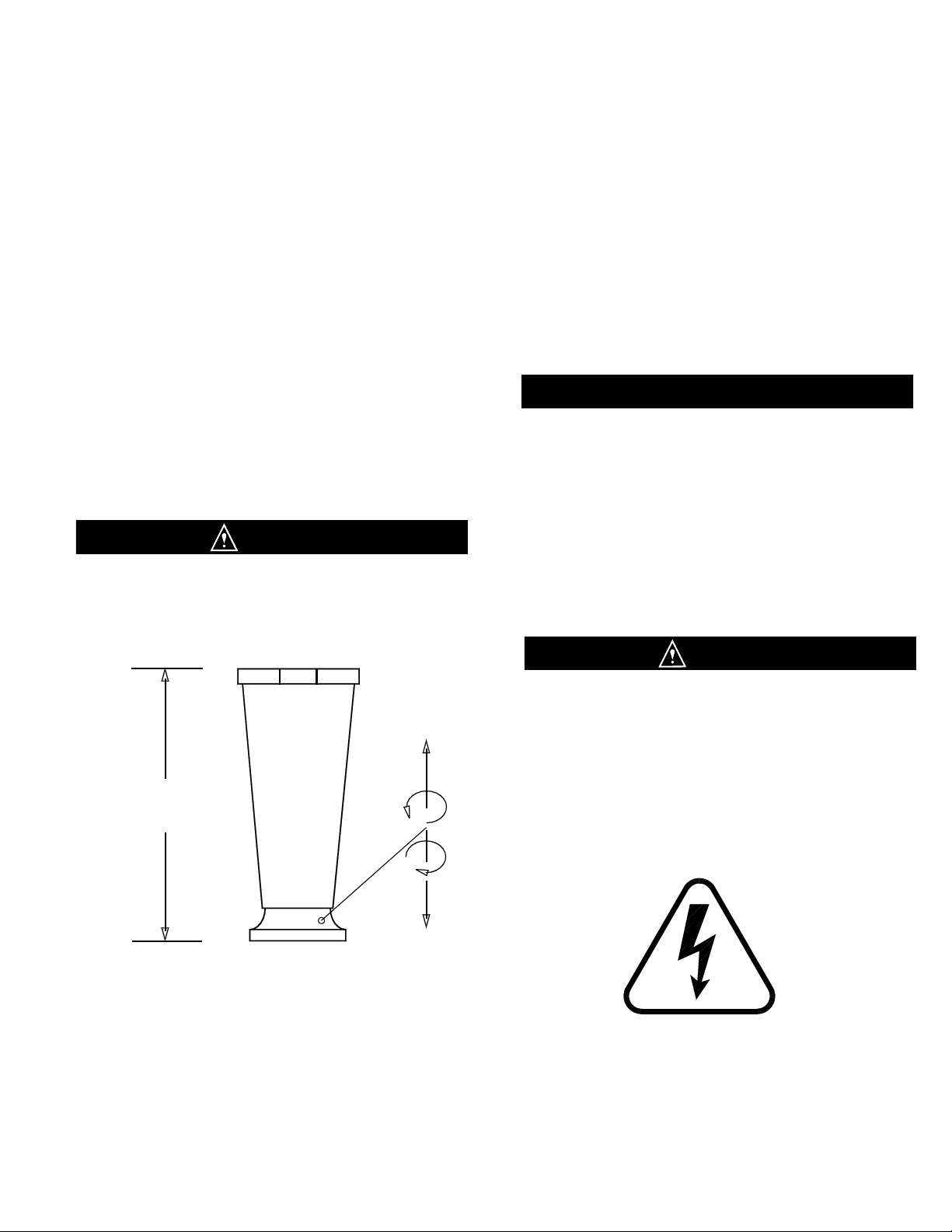
9. Remove the front plate (Fig. 6) by turning the black plas-
tic knobs in a counterclockwise direction.
Disassemble the front plate in the following manner:
a. Remove the faspin and spigot handle.
b. Remove the front plate o-ring.
c. With the spigot handle removed, push the spigot
plunger out the top of the front plate and remove all
lubricant from the spigot plunger.
d. Remove the three o-rings from the spigot plunger
(Fig. 7) by grasping the part with one hand and with
a dry cloth in the other hand, squeeze the o-ring up-
ward. When a loop is formed, grasp the o-ring with
the other hand and roll it out of its groove and off the
spigot plunger .
e. Remove pressure relief plug and remove the two O-
rings from the plug.
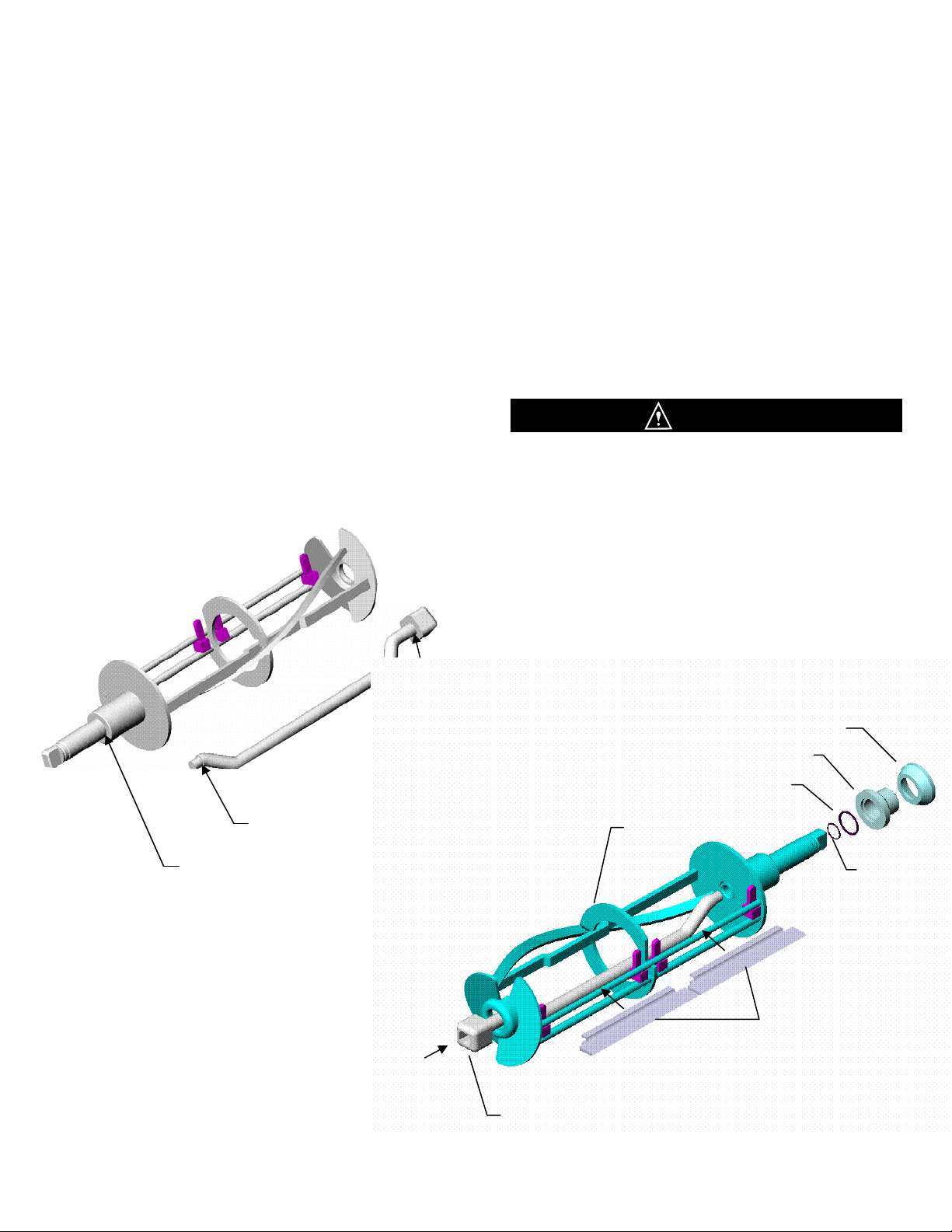
9. Remove the dasher assembly (Fig. 8) being careful not to
damage the scraper blades, then disassemble in the follow-
ing manner:
a. Remove the rear seal assembly
b. Remove the stator rod from the dasher.
c. Remove the blades from the dasher by first rotating
blade upward and then unsnapping one end from the
support rod (see Fig. 9).
d. Remove o-ring from the rear of the dasher.
e. Separate the GREY rubber rear seal from the rear bear-
ing and remove the rear bearing O-ring.
Fig. 6
Front Plate
Fig. 8
Scraper Blades (2)
Dasher
Stator Rod
Rear Bearing O-Ring
Rear Seal
Dasher O-Ring
BLADES
MUST BE
REMOVED FOR CLEANING
Rear Bearing
Plunger O-Rings

Dasher Front
View
Scraper Blade
Blade Support
Tab
Support
Rod
Blade Support
Tab
Support
Rod
Dasher Front
View
Scraper Blade
Fig. 9
Scraper Blade Removal
DISASSEMBLY and CLEANING
PAGE 5
10. Remove the drip tray insert and drip tray (Fig. 10).
11. Remove the top cover of the machine by removing the
phillips head screw in the back of the top cover Turn
the three knobs on the expansion chamber (Fig. 11)
counter-clockwise and remove the chamber top.
12. Place all parts in a three partition sink filled with the
following solutions:
a. In the first partition, a solution of water and anti-
bacterial dishwashing detergent.
b. In the second partition, clear rinse water.
c. In the third partition, sanitizing rinse solution
equivalent to 200 parts per million (PPM)
Chlorine residual.
13. Pour a portion of the detergent solution in the
expansion chamber and clean the chamber and
freezing chamber with the brush provided.
14. Place all removable items in the sink and clean all
holes and ports with brushes.
15. Rinse the parts in the clear rinse water and place them
in the sanitizing solution for at least three minutes and
then allow them to air dry before assembly and
lubrication.
Drip Tray
Support
Drip Tray
Drip
Fig. 10
Drip Tray Assembly
Fig. 11
Expansion Chamber

c. Install the o-ring on the rear of the dasher shaft.
DO NOT LUBRICATE DASHER O-RINGS
d. Assemble and install the rear seal with the rubber
portion toward the rear of the freezing cylinder as
indicated in Fig. 13.
DO NOT LUBRICATE THE RUBBER PORTION OF
THE REAR SEAL. LUBRICATION ON THE REAR
SEAL WILL DAMAGE THE MACHINE.
Use a food grade lubricant ONLY. Sanigel (SaniServ part number 188490) is recommended and is available from the
factory or your local authorized SaniServ dealer or distributor.
ASSEMBLY and LUBRICATION
Fig. 24a
Stator Rod and Dasher Lubrication
PAGE 6
Assembly and Lubrication
1. Lubricate and assemble the dasher assembly in the
following manner:
a. Apply a generous amount of lubricant to the
shoulder of the dasher and the area of the shaft
where the white plastic portion of the assembled
rear seal contacts the shaft (Fig. 12). This is easily
performed by running a 1/4” (6 mm) bead of
lubricant around the shoulder of the dasher.
b. Lubricate the two areas of the stator rod (Fig. 12)
and slide the stator rod into the dasher (Fig. 13).
Make certain that the end of the stator rod is
inserted into the hole at the rear of the dasher.
Fig. 13
Dasher Assembly
CAUTION
Fig. 12
Stator Rod
and
Dasher Lubrication
Lubricate This Face and Surface
Approx. 1 Inch Back From This
Edge
Lubricate This Face
Rear Seal
Rear Bearing
Dasher O-Ring
Rear Bearing O-Ring
Scraper Blades (2)
Dasher
Stator Rod

e. Install the scraper blades onto the dasher assembly
by holding the blades perpendicular to the tabs (Fig.
14) and then snapping them over the flat area of the
support rod. Then rotate the blades downward in a
counterclockwise direction as viewed from the front
of the dasher (Fig. 15). BE CERTAIN THAT THE
SCRAPER BLADES REST UPON THE DASHER
TABS.
Note: Reverse the blades at each cleaning to maintain
sharpness. In addition, the blades are equipped
with a wear mark (Fig. 16). When the blade is
worn to this wear mark, it must be replaced.
Blade Support
Tab
Support Rod
Dasher Front View
Scraper Blade
Dasher Front
View
Blade Support
Tab Support Rod
Scraper Blade
Rotate Down
Counter
Clockwise
Scraper Blade Wear Mark
End
View
Side
View
ASSEMBLY and LUBRICATION
PAGE 7
Fig. 15
Scraper Blade Installation
Fig. 14
Scraper Blade Installation
Fig. 16
Scraper Blade Wear Mark
f. Insert the dasher assembly into the freezing cylinder
as far as possible (Fig. 17) being careful not to
damage the scraper blades. Damage will occur to
the scraper blades and the dispenser will not
operate properly if the scraper blades are installed
facing in a clockwise direction (Fig. 18).
Note: The stator rod has been deleted from Fig. 17 and
Fig. 18 for clarity only. The stator rod must be installed
for proper machine operation.
g. While maintaining force against the dasher, rotate it
slowly until the tongue of the dasher engages the
groove in the drive system at the rear of the cylinder.
The outer most portion of the dasher should be
recessed approximately 1/4” (6 mm) to 3/8” (10 mm)
inside the freezing cylinder. No part of the dasher
should extend outside the cylinder. Scraper blades
should be visible, extending approximately 1/8” (3
mm) beyond the dasher
(Fig. 19).
Fig. 17
Dasher Installation
CORRECT
Blades
Resting On Tabs
Blades Pointing In A
Counterclockwise
Direction
Fig. 18
Dasher Installation
Blades Should
Rest On Tabs
Blades Should Not Point
In A Clockwise Direction
INCORRECT

Spigot Handle
Spigot Plunger
(3) O-Rings
Front Plate O-Ring
DO NOT LUBRICATE
Front Plate Knob
Front Plate Knob
Faspin
Front Plate
Pressure Relief Plug
(2) O-Rings
2. Lubricate and assemble the front plate assembly in
the following manner:
a. Install the three o-rings on the spigot plunger AND
two O-rings on the Pressure Relief Plug by
rolling them onto the plunger. Seat the o-rings in
the grooves. Be certain that they are not twisted.
Smooth the lubricant into the grooves and over
the sides of the plunger and Pressure Reief Plug
assemblies (Fig. 21).
b. Slide the lubricated spigot plunger and Presure
Relief Plug into the front plate (Fig. 20) making
certain that the spigot handle slot is aligned to the
front.
C. Insert the spigot handle and secure with the faspin.
d. Install the front plate o-ring.
DO NOT LUBRICATE THE FRONT PLATE O-RING
e. Secure the front plate assembly with the two
plastic knobs. Simultaneously, turn the knobs in a
clockwise direction. Tighten the knobs evenly.
DO NOT tighten one knob all the way down and
then the other. Doing so may result in front plate
breakage. Only moderate force is required.
DO NOT over tighten. Close the spigot plunger.
5. Install the drip tray and drip tray insert .
PAGE 8
Fig. 19
Dasher with Blade (Front View)
Fig. 20
Front Plate Assembly
ASSEMBLY and LUBRICATION
Approximately 1/8 inch
Exposed
Fig. 21
Spigot Plunger / Relief Plug
Lubrication
Lubricate This
Area
Lubricate This
Area

Front Plate: This component is the plastic device from which the product is dispensed. It is designed and
made for strength and durability. However, through improper use, it can be damaged. Use the following
information for proper care.
1. Do not lubricate the large o-ring on the rear of the front plate. If lubricated, it will not seal properly and
product will leak from the front plate.
2. Do not over tighten the knobs.
3. Always tighten the front plate knobs evenly. Do not attempt to turn one knob all the way down and then
the other. Doing so will bind the front plate and result in breakage.
4. Improper installation of the stator rod can cause breakage. The stator rod must be properly seated in the
dasher before installing the front plate. If the stator rod is improperly installed, subsequent tightening of the
knobs will break the front plate.
5. Do not attempt to wash the front plate or any other machine components in a dishwasher.
HELPFUL HINTS
Helpful Hints
PAGE 11

Initial adjustments have been performed at the factory.
However, to satisfy individual product preferences, the
following adjustments may be required:
1. Remove power, then remove the right side panel
(guard) as viewed from the front of the machine.
2. Using a regular straight flat blade screwdriver, turn
the mechanical consistency (torque adjustment) screw
(Fig. 22) clockwise to make the product harder or
counterclockwise to make the product softer. Do not
adjust more than one turn each time.
Do not attempt to adjust the belt idler screw marked
“Do Not Adjust”.
EXTREME CARE SHOULD BE EXERCISED TO KEEP
HANDS AND TOOLS AWAY FROM MOVING PARTS.
PERSONAL INJURY COULD RESULT.
WARNING: Adjustments to the mechanical consistency control system should be made ONLY by trained service
personnel. Power must be removed from the machine before panels (guards) or protective covers are removed.
Once the panels (guards) are removed, an adjustment is made, protective panels (guards) are replaced, power is
restored to the machine, and the consistency setting is tested. This process is repeated as necessary until the
desired product consistency is obtained.
The mechanical control system is a very simple method of controlling the consistency of the finished product. The machine
operates without a temperature control. Refrigeration is controlled by measuring the torque on the dasher motor and the
consistency of the product. The tension of a spring against the torque idler determines the consistency of the product.
Fig. 22
Mechanical Consistency
Control
CONSISTENCY ADJUSTMENT
Consistency Adjustment
PAGE 12
3. Replace the side panel (guard), restore power, and
start the machine. Wait 10 - 15 minutes or until the
compressor cycles off, then check the consistency of
the product.
4. Repeat steps 1, 2 and 3 until the desired product
consistency is obtained.
WARNING
CAUTION

Routine Maintenance (Trained Service Technician)
Routine Maintenance (Owner-Operator)
ROUTINE MAINTENANCE
PAGE 13
Scraper Blade Wear Mark
End
View Side
View
Fig. 23
Scraper Blade Wear Mark
CONDENSER FINS ARE VERY SHARP
USE EXTREME CAUTION WHEN CLEANING
Quarterly: Thoroughly clean the condenser fins on all
air-cooled machines. Remove all lint and dust with a
vacuum cleaner or compressed air (Fig. 24) to clean fins.
A dirty condenser greatly reduces refrigeration capacity
and efficiency. When using compressed air, place a
damp cloth on the opposite side of the condenser to catch
the flying dirt or lint.
Annually: Check the belts for signs of wear or cracking.
Remove panels and clean all parts inside of the machine
including the base, side panels, fan blades, condensers,
etc.
DISCONNECT THE MACHINE FROM ITS POWER
SOURCE(S) BEFORE PERFORMING ANY ROUTINE
MAINTENANCE. PERSONAL INJURY OR DAMAGE
TO THE MACHINE COULD RESULT IF THIS
PRACTICE IS NOT OBSERVED.
Daily: Inspect the machine for signs of product leaks
past seals and gaskets. If proper assembly does not
stop leaks around gaskets or seals, check for improper
lubrication and worn or damaged parts. Replace parts as
needed.
Periodically: Inspect the scraper blades (Fig. 23) to see
that they are straight and sharp. If worn, damaged or
warped, the blades will not scrape the cylinder walls
correctly and the freezing capacity will be reduced. Clean
the drip chute assembly (Fig. 25 with warm water and
detergent solution.
Fig. 24
Clean Sharp Condenser Fins
WARNING
WARNING
Fig. 25
Drip Chute

PAGE 14
ROUTINE MAINTENANCE
HAZARDOUS MOVING PARTS
Semiannually: It is advisable to clean and lubricate the
idler arms (Fig. 26) to ensure their smooth operation. Use
the following procedures:
1. Make certain that ALL power to the dispenser is off.
2. Remove both side panels first, then remove the rear
panel of the machine.
3. Use a pencil to mark the position of the nut (Fig 26) on
the side of the belt idler arm spring adjustment
mechanism. Relieve the tension on the spring by turning
the adjustment screw near the label which warns: DO
NOT ADJUST. Disconnect the spring from the belt idler
arm by placing needle nose pliers on one end of the
spring and pulling the end out of the retainer.
4. Remove the nut from the pivot point of the belt idler
arm assembly.
5. Remove the belt idler arm and inspect the pivot point
sleeve. These areas should be free of rust, debris, or
dried lubricant. If any of these substances are found,
they must be removed.
6. Clean and polish the sleeve surface with a fine grade
of emery cloth.
7. Reinstall the belt idler arm.
NOTE: BE CERTAIN NOT TO OVERTIGHTEN THE
LOCKING NUT. ON SOME UNITS IT IS POSSIBLE TO
OVERTIGHTEN THE LOCKING NUT AND CAUSE THE
IDLER ARMS TO BIND. THE ARMS SHOULD MOVE
FREELY.
8. Repeat the process for the torque idler arm.
9. Install the belt making certain that there is no grease
on the belt or pulleys. Step to the side of the unit and
view the belt to determine whether or not it is properly
aligned (straight from top to bottom).
10. Reinstall the silver torque idler arm spring and the
silver belt idler arm spring and turn the adjustment screws
returning the adjustment nuts to the pencil marks you
placed on the side of each adjustment mechanism in step
3 above.
11. Repeat steps 3 - 9 for the other side if your machine
has two freezing cylinders and then place the unit back
into operation. Check the product for proper consistency
and adjust as required. When the consistency is right,
replace the rear and both side panels.
Fig. 26
Spring Adjustment Mechanism
Torque Idler Arm Pivot
Rotation
Rotation
Torque
Adjustment
Mark Nut
Position
With Pencil
Mark Nut Position
With Pencil
Belt Idler
Arm Pivot
Routine Maintenance (Trained Service Technician)
WARNING

TROUBLESHOOTING
If product will not freeze to proper consistency:
1. Check for dull scraper blades making certain that they have been rotated. Replace as necessary.
2. Check the condenser for dirt or obstructions. See Quarterly Maintenance.
3. Make certain that the compressor and fan will run.
4. Check consistency adjustments and belt wear. Adjust or replace the belt as necessary.
If squeaking or chirping noises are heard:
1. Check belt tension. Replace worn belts.
2. Check rear seals. Replace if necessary.
3. Check lubrication.
If compressor does not run:
1. Inspect the torque arm for free movement.
2. Check the torque switch. It must click when depressed. See Consistency Adjustment.
3. Inspect the condenser for dirt or obstruction. See Routine Maintenance.
4. Check for proper clearance around the machine.
If equipment leaks:
1. Check o-rings and seals. Replace as necessary.
2. Check for proper lubrication. Lubricate per instructions.
If unit freezes up:
1. Damage from previous freeze-up. Check freezing cylinders, dashers, blades, stator rods.
2. Freezing cylinder surfaces too cold. Adjust suction pressure.
3. Missing scraper blades, stator rods, or dasher assemblies. Check these assemblies.
4. Make refrigeration adjustments.
Troubleshooting
PAGE 15
NOTE: Bold items in Italics should be performed by trained Service Technicians.

PAGE 16
ASSEMBLY DIAGRAM

Notes

Service Log

“Reliability from the team that Serves the Best”
SaniServ P.O. Box 1089 Mooresville, Indiana 46158
P/N 82259
Rev. A
021303
SaniServ®
An AFFINIS GROUP Company
Table of contents
Other SaniServ Beverage Dispenser manuals
Popular Beverage Dispenser manuals by other brands

Flavor Burst
Flavor Burst TS 44BEV user manual

Servend
Servend FlexTower 8 Installation & service guide

Follett
Follett VU300 Installation, operation & service manual

Napa Technology
Napa Technology Pristine PLUS CX user manual

Krups
Krups BEERTENDER VB2158 user manual

lancer
lancer Sensation 30 installation guide