-3-
VI. Installation and debugging
Determine the location, mounting distance and numbers for mounting the detectors in the protection
area according to relevant provisions and regulations of GB50116-98 Code for Design of Automatic Fire
Alarm System and GB50166-2007 Code for Installation and Acceptance of Fire Alarm System.
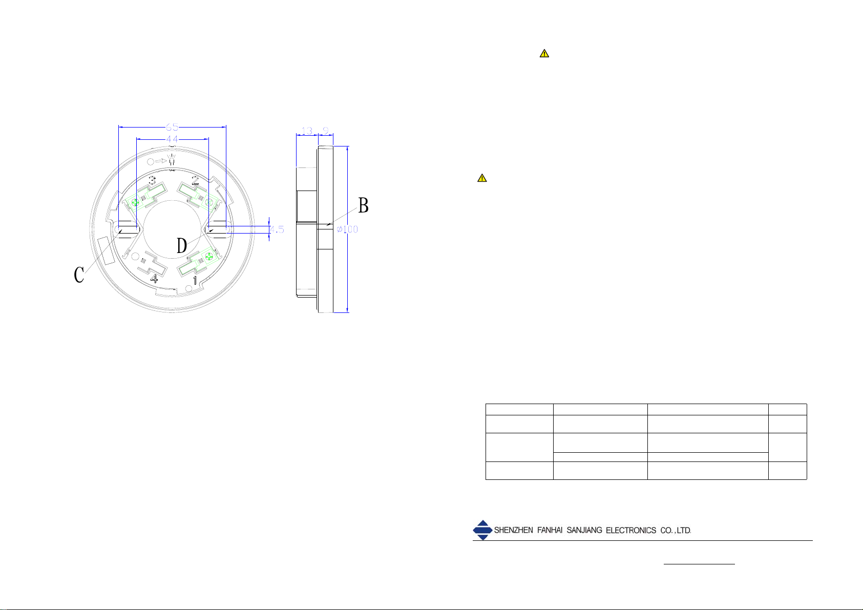
A self-contained complete base is necessary during the installation of a detector. As shown in Fig.5,
the model, the external dimensions, the mounting hole diameter and the mounting hole spacing of the
base are DZ-910K, Φ100mm×22mm (diameter×thickness), Φ4.5mm and 44mm~65mm respectively.
C
D
DZ-910K
B
Fig.5
Wiring requirement: It is proper to use RVS twisted pairs with a section area of equal to or larger
than 1.0mm2for the signal buses L1 and L2.
Specific installation and debugging methods:
1. Make sure the type of the detector matches the type of the host machine of the fire alarm
control panel;
2. Use two M4 screws to fix the matched mounting base on the designated position via the
mounting holes C and D shown in Fig.5, as instructed in the construction drawing and make
sure the matched mounting base has been firmly installed.
3. Disconnect the power supply of the fire alarm control panel and connect the detector correctly
according to the construction drawing.
4. Place the indicator at position A of the detector (see Fig.1) and position B of the base (see
Fig.5), align them with each other, insert the detector into the base and turn the detector
clockwise until it is firmly locked.
5. After all the products are installed and checked, connect the power supply of the fire alarm
control panel.
6. When the detector is powered up normally, the red indicator of the detector will blink once about
every 3~6 seconds, which suggests that the detector has begun to operate normally.
7. Finally conduct an alarm test for the detector through some special tools or direct hot air gun
blowing. After the detector gives a fire alarm, the indicator will remain lit and the fire alarm
control panel will simultaneously give corresponding alarm prompt information. After the alarm
test, reset the fire alarm control panel and restore to the monitoring status.
-4-
VII. Precautions
1. The connected detectors shall be 50 units max when the JTW-ZD-920KE is connected with
intelligent fire alarm control systems via a interface module.
2. Never dismount the protective cover delivered with the detector too early after the field
installation and before the use of the detector, or else the detector may be contaminated.
3. It is not permitted to use open flames (such as lighters) to firing thermistor during alarm tests,
so as to avoid damage to the detector. It is recommended to use a hot air gun and other heating
equipment in a simulation alarm test.
4. The protection area and quantity of the detectors should comply with relevant provisions in
GB50116-98 Code for Design of Automatic Fire Alarm System and GB50166-2007 Code for
Installation and Acceptance of Fire Alarm System.
VIII. Maintenance
Warning: Before conducting maintenance for a detector, inform the related management
department that the monitoring will be stopped temporarily when the system maintenance.
Meanwhile, disable the logic control function of the area or system to be maintained to avoid
unnecessary alarm linkage. After the test, inform the management department to restore the
normal functions of the system.
1. According to the requirements of GB50166-2007 Code for Installation and Acceptance of Fire
Alarm Systems, each quarter, some special testing instruments should be used to test the
detector’s operation and confirm the indication state of its indicators by batch and stage; for a
detector that has been installed and used, It is recommended to have it maintained once every
two years.
2. If a detector fails due to a material defect or a manufacturing process defect under normal
conditions of use in one year following the date of its delivery, we shall repair or replace it for
free. However, the faults of the detector due to artificial damage, improper use, or authorized
adjustment, reconstruction or disassembly are not covered in the guarantee and we shall
assume no responsibilities for any the consequence thereby caused.
3. We may provide paid repair service for products with any faults beyond the guarantee range. If
you have such products that need repair, please contact us. When sending such a product to
us for repair, you are expected to provide some important information about the product, such
as the phenomenon and possible cause of the product fault, so that we can find out the cause
of the fault in the shortest time and so the information may be used as a reference in our future
product development and improvement.
IX. Fault analysis and troubleshooting
Failures Causes Methods Remarks
Alarm after
powered up Internal circuit is broken Return to the manufacturer for
repairs
Cannot work after
powered up
Internal circuit is broken Return to the manufacturer for
repairs
Bad contact to the base Inspect and reinstall the base
Cannot alarm
during test Internal circuit is broken Return to the manufacturer for
repairs
Address:3F, Guangcai New World Building, Nanshan Road, Nanshan District, Shenzhen, 518054, P.R.China
Tel:+86(755)86226969 Fax::+86(755)86223939 Http://www.fhsjdz.com


