manuals.online logo
Brands
  1. Home
  2. •
  3. Brands
  4. •
  5. Sansui
  6. •
  7. Amplifier
  8. •
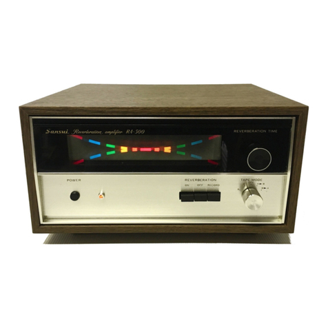
  9. Sansui RA-700 User manual

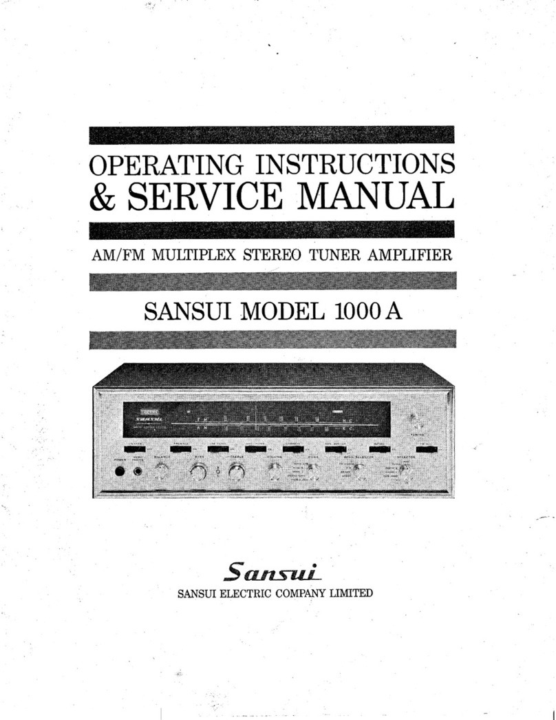
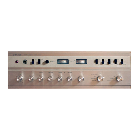
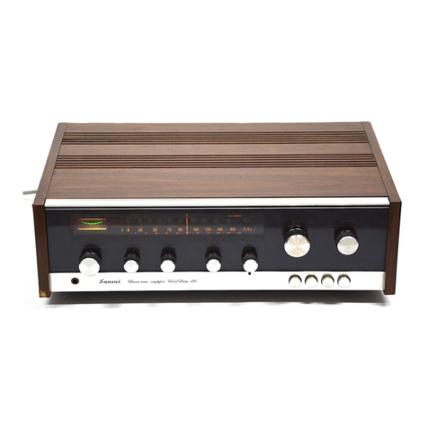
Sansui RA-700 User manual

Other manuals for RA-700

1

Other Sansui Amplifier manuals

Sansui AU-999 Troubleshooting guide

Sansui

Sansui AU-999 Troubleshooting guide

Sansui AU-666 Troubleshooting guide

Sansui

Sansui AU-666 Troubleshooting guide

Sansui 5000X User manual

Sansui

Sansui 5000X User manual

Sansui AU-919 User manual

Sansui

Sansui AU-919 User manual

Sansui AU-6500 Troubleshooting guide

Sansui

Sansui AU-6500 Troubleshooting guide

Sansui AU-X201 User manual

Sansui

Sansui AU-X201 User manual

Sansui BA-2000 User manual

Sansui

Sansui BA-2000 User manual

Sansui 210 Troubleshooting guide

Sansui

Sansui 210 Troubleshooting guide

Sansui AU-9900A User manual

Sansui

Sansui AU-9900A User manual

Sansui 2000 User manual

Sansui

Sansui 2000 User manual

Sansui AU-517 User manual

Sansui

Sansui AU-517 User manual

Sansui 3000 User manual

Sansui

Sansui 3000 User manual

Sansui 1000X User manual

Sansui

Sansui 1000X User manual

Sansui AU-D33 User manual

Sansui

Sansui AU-D33 User manual

Sansui 1000A Troubleshooting guide

Sansui

Sansui 1000A Troubleshooting guide

Sansui SAP201V User manual

Sansui

Sansui SAP201V User manual

Sansui AU-101 Troubleshooting guide

Sansui

Sansui AU-101 Troubleshooting guide

Sansui AU-777 User manual

Sansui

Sansui AU-777 User manual

Sansui AU-7700 User manual

Sansui

Sansui AU-7700 User manual
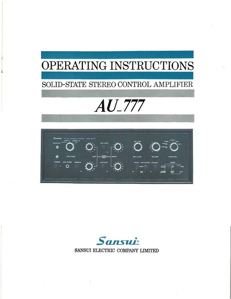
Sansui 2000A User manual

Sansui

Sansui 2000A User manual

Sansui 1000A Troubleshooting guide

Sansui

Sansui 1000A Troubleshooting guide
Sansui AU-555A Troubleshooting guide

Sansui

Sansui AU-555A Troubleshooting guide

Sansui AU-777A Troubleshooting guide

Sansui

Sansui AU-777A Troubleshooting guide

Sansui AU-G55X User manual

Sansui

Sansui AU-G55X User manual

Popular Amplifier manuals by other brands

Magnat Audio EDITION FOUR Owner's manual/warranty document

Magnat Audio

Magnat Audio EDITION FOUR Owner's manual/warranty document

Inter-m PA-2000A Operation manual

Inter-m

Inter-m PA-2000A Operation manual

Yamaha TX6n owner's manual

Yamaha

Yamaha TX6n owner's manual

Peavey TNT 150 user guide

Peavey

Peavey TNT 150 user guide

Bosch LBB 1903/10 Installation and user instructions

Bosch

Bosch LBB 1903/10 Installation and user instructions

Avocent Emerge DA1200D Installer/user guide

Avocent

Avocent Emerge DA1200D Installer/user guide

Redgum RGi35 operating instructions

Redgum

Redgum RGi35 operating instructions

Cambridge Audio AXA25 user manual

Cambridge Audio

Cambridge Audio AXA25 user manual

Alpine MRP-M200 owner's manual

Alpine

Alpine MRP-M200 owner's manual

Technical Pro H1502UrBT user manual

Technical Pro

Technical Pro H1502UrBT user manual

FMS EMGZ307 operating manual

FMS

FMS EMGZ307 operating manual

Racal Instruments 5601 user manual

Racal Instruments

Racal Instruments 5601 user manual

Valcom V-1094A Technical specifications

Valcom

Valcom V-1094A Technical specifications

Cambridge Audio 851D user manual

Cambridge Audio

Cambridge Audio 851D user manual

QSC 3800 Specifications

QSC

QSC 3800 Specifications

NAD C300 owner's manual

NAD

NAD C300 owner's manual

Rotel RMB-1077 owner's manual

Rotel

Rotel RMB-1077 owner's manual

Peavey Monitor 300 Series operating guide

Peavey

Peavey Monitor 300 Series operating guide

manuals.online logo
manuals.online logoBrands
  • About & Mission
  • Contact us
  • Privacy Policy
  • Terms and Conditions

Copyright 2025 Manuals.Online. All Rights Reserved.

OPERATING
INSTRUCTIONS
SOLID-STATE
REVERBERATION
AMPLIFIER
SANSUI
RA-700
Sansut.
SANSUI
ELECTRIC
CO.,
LTD.
Congratulations
on
joining
the
thousands
of
proud,
satisfied
owners
of
quality
stereo
components
from
Sansui.
The
RA-700
reverberation
amplifier
is
a
unique
com-
ponent
to
add
a
new
thrilling
pleasure
to
your
stereo
enjoyment.
It
can
provide
reverberation
effects
to
all
the
program
sources
set
up
on
your
existing
stereo
control
amplifier,
including
the
playback
from,
record-
ing
on
a
tape
deck,
and
dubbing
between
two
tape
decks.
The
continuously
controllable
reverberation
time,
multicolored
reverberation
indicator
and
other
new
ideas
have
been
engineered
into
the
RA-700.
This
manual
has
been
prepared
to
guide
you
in
con-
necting
and
operating
the
reverberation
amplifier
cor-
rectly.
Please
read
it
carefully
before
operating
the
amplifier
and
retain
it
for
future
reference.
CONTENTS
SWITCHES
AND
CONTROLS
orcsssssscasnacsvcennsnnve
3
CORINEC
TIONS
assicnestesrassemenessooncasenndenceisancyewsnt
4
CONNECTIONS/OPERATION
ccsiccerssnsnanvaswes
5,
6
HINTS
ON
USE/ACCESSORIES
wisi
ss
sssvnnsnnucnes
7,8
SPECIFICATIONS/BLOCK
DIAGRAM
................
9
BGHEMA
TIC
DIAGRAM
cscxscssnsmnsstessianasconsesies
10
REVERBERATION
TARE
MOLE
ON
OFF
RECORD
ae
is
are
8
‘Be
A
on
Sansui.
%
REVERBERATION
AMPLIFIER
—
SWITCHES
AND
CONTROLS
REVERBERATION
INDICATOR
The
reverberation
indicator
is
illuminated
when
the
Reverberation
On
or
Record
button
is
de.
pressed.
The
two
rainbows,
one
inverted,
draw
sharply
and
distinctly
apart
as
the
reverberation
REVERBERATION
TIME
CONTROL
Use
this
control
to
adjust
the
reverberation
time
while
watching
the
reverberation
indicator.
To
lengthen
the
time,
turn
it
clockwise;
to
shorten
the
time,
turn
it
counterclockwise.
time
is
shortened.
POWER
REVERBERATION
TAPE
MODE
Orr
ON
OFF
RECORD
ae
‘APB
Sansui
REVERBERATION
AMPLIFIER
RA-700
is
Ok
a
+e
A
O
OFF
POWER
SWITCH
Push
this
switch
once
to
turn
the
power
on;
push
it
again
to
turn
the
power
off.
POWER
INDICATOR
The
power
indicator
is
lit
when
the
Power
switch
is
turned
on.
It
remains
lit
while
the
amplifler
is
on.
REVERBERATION
PUSHBUTTONS.
ON—Depress
this
button
to
add
reverberation
to
any
program
source.
If
it
is
depressed
during
the
recording
process,
the
recording
is
made
without
reverberation
but
only
the
sound
from
the
speakers
is
reverberated.
OFF—Depress
this
button
if
you
want
not
to
add
reverberation
during
the
recording
process
or
while
listening
to
records,
radio
broadcasts
or
tapes.
RECORD—Depress
this
button
to
add
reverbera-
tion
to
the
sound
of
the
recording.
TAPE
MODE
SELECTOR
B—Use
this
position
to
record
on,
or
play
back
through,
the
tape
deck
connected
to
the
TAPE
DECK
B
jacks.
A—Use
this
position
to
record
on,
or
play
back
through,
the
tape
deck
connected
to
the
TAPE
DECK
A
jacks.
OFF—Use
this
position
to
provide
reverberation
effects
to
a
program
source
set
up
on
the
receiver
(or
control
amplifier)
connected
to
the
RA-700.
With
the
selector
switched
to
this
position,
the
reverberation
amplifier
is
disconnected
from
the
tape
deck
circuits.
Ap
B—uUse
this
position
to
record
from
the
tape
deck
A
to
the
tape
deck
B.
Bp
A—Use
this
position
to
record
from
the
tape
deck
B
to
the
tape
deck
A.
CONNECTIONS
GROUNDING
TAPE
DECK
Sarsvwe
poo
am
AMPLIFIER
ages
|
i
cia
|
REC
PLAY
REC
PLAY
UNSWITCHED
TOTAL
300VA
MAXIMUM
TO
TAPE
_—
TURNTABLE,
ETC.
a
~b
PHONO
TUNER
AUX
pila
o5
te
=f
y
,
=
OO
Le)
oO
~
WALL
AC
OUTLET
“90006
REAR
PANEL
OF
RECEIVER
(or
control
amplifier)
TO
INPUTS
TO
OUTPUTS
TOINPUTS
OF
TAPE
OF
TAPE
OF
TAPE
DECK
A
DECK
A
DECK
B
TO
OUTPUTS
OF
TAPE
DECK
B
TAPE
DECKA
TAPE
DECK
B
CONNECTIONS
OPERATION
TAPE
DECK
A
TAPE
DECK
B
PLAYBACK
=
RECORDING<=
RECEIVER
OR
RA-700
CONTROL
AMPLIFIER
OUTPUTS
seams
™
ee
ROO
REVERBERATION
AMP.
INPUTS
WALL
AC
OUTLET
CONNECTION
TO
RECEIVER
OR
CONTROL
AMPLIFIER
RA-700
RECEIVER
OR
REVERBERTION
AMP
CONTROL
AMP
TAPE
(REC)
Outputs
L
et
©
i=
©
maar
CONNECTION
OF
TAPE
DECK
TO
RA-700
RA-700
TAPE
DECK
J
=>
PLAYBACK
TURNTABLE
KXYXE
XK
Mnneuacntne
RS,
KX
)
()
ORK
KY
RY
SPEAKER
SYSTEMS
LEFT
RIGHT
To
Reverberate
Sound
From
Any
Pro-
gram
Source—Record
Player,
Tuner
or
Microphone—Except
Tape
Deck
1.
Set
the
Tape
Monitor
switch
on
the
receiver
(or
control
amplifier)
to
its
PLAYBACK
or
ON
position.
2.
Turn
the
Tape
Mode
selector
on
the
RA-
700
to
its
OFF
position.
3.
Depress
the
Reverberation
On
button.
4.
Adjust
the
Reverberation
Time
control
to
the
desired
reverberation.
To
Reverberate
Sound
From
or
Through
the
Tape
Deck
Playback
1.
Set
the
Tape
Monitor
switch
on
the
receiver
(or
control
amplifier)
to
its
PLAYBACK
or
ON
position.
2.
Turn
the
Tape
Mode
selector
on
the
RA-
700
to
A
or
B
depending
on
which
jacks
are
being
used
for
playback.
3.
Depress
the
Reverberation
On
button.
4.
Operate
the
tape
deck
in
the
playback
mode.
5.
Adjust
the
Reverberation
Time
control
to
the
desired
reverberation.
Recording
1.
Set
the
Tape
Monitor
switch
on
the
receiver
(or
control
amplifier)
to
its
PLAYBACK
or
ON
position.
2.
Turn
the
Tape
Mode
selector
on
the
RA-
700
to
A
or
B
depending
on
which
jacks
are
being
used
for
recording.
3.
Depress
the
Reverberation
Record
button.
4.
Operate
the
tape
deck
in
the
recording
mode.
5.
Adjust
the
Reverberation
Time
control
to
the
desired
reverberation.
Notes:
¢
If
the
Reverberation
On
button
is
depressed
during
the
recording
process,
the
original
pro-
gram
can
be
recorded
without
reverberation
while
the
reverberated
sound
comes
from
the
speakers.
¢
If
the
Reverberation
Off
button
is
depressed
during
the
recording
process,
no
reverberation
is
added
to
the
sound
of
the
recording
nor
to
the
sound
from
the
speakers.
Dubbing
1.
Set
the
Tape
Monitor
switch
on
the
receiver
(or
control
amplifier)
to
its
PLAYBACK
or
ON
position.
2.
When
recording
from
the
tape
deck
A
to
the
tape
deck
B,
turn
the
Tape
Mode
selector
to
APB;
when
recording
from
the
B
to
the
A,
turn
the
selector
to
BRA.
3.
Depress
the
Reverberation
Record
button.
4.
Operate
one
tape
deck
in
the
playback
mode
and
another
in
the
recording
mode.
5.
Adjust
the
Reverberation
Time
control
to
the
desired
reverberation.
Note:
If
you
want
not
to
add
reverberation
during
the
dubbing
process,
depress
the
Rever-
beration
Off
button.
If
the
Reverberation
On
button
is
depressed
during
the
dubbing
process,
the
original
tape
can
be
recorded
without
re-
verberation
while
the
reverberated
sound
comes
from
the
speakers.
Monitoring
If
your
tape
deck
has
its
own
preamplifier
as
well
as
separate
recording
and
playback
heads,
you
can
monitor
the
tape
instantly
after
the
recording
is
made
and
while
the
recording
is
still
in
progress.
For
use
with
a
two-head
tape
recorder
which
can
pick
up
a
signal
before
the
recording
is
made,
you
can
listen
to
it
as
well.
If
a
two-head
tape
recorder
which
does
not
employ
this
arrangement
is
used
for
recording,
not
playback,
the
Tape
Monitor
switch
on
the
control
amplifier
(or
receiver)
should
be
set
to
its
SOURCE
or
OFF
position,
otherwise
no
sound
comes
from
the
speakers.
—_
HINTS
ON
USE/
ACCESSORIES
Connections
Be
sure
to
use
shielded
cable
(four
connecting
cords
supplied)
to
connect
a
control
amplifier
and
tape
decks
to
the
RA-700.
The
use
of
an
ordinary
twin
leadwire
may
cause
hum
or
noise.
Always
check
to
see
if
the
connecting
cords
are
plugged
firmly
and
properly
into
their
corresponding
output
or
input
jacks.
If
the
connections
are
loose
or
in
touch
with
other
parts,
the
RA-700
will
not
perform
normally,
and
may
produce
undesirable
noise.
If
used
in
such
a
way
for
a
long
time,
it
will
eventually
break
down.
A.C.
Outlets
The
two
a.c.
outlets
on
the
rear
panel
are
live
at
all
times
and
for
plugging
in
a
pair
of
tape
decks.
The
voltage
delivered
at
these
AC
out-
lets
is
the
same
as
the
power
supply
voltage
used.
They
have
a
maximum
capacity
of
300
VA
total.
Never
use
them
beyond
their
rated
capacity.
UNSWITCHED
TOTAL
300VA
MAXIMUM
Power
Fuse
If
the
unit
remains
completely
dead
when
the
power
is
switched
on
(the
POWER
indicator
fails
to
light),
the
power
fuse
is
probably
blown.
In
this
case,
remove
the
line
cord
from
its
a.c.
outlet
and
replace
the
fuse
after
finding
and
eliminating
the
trouble
that
caused
the
fuse
to
blow.
Use
only
an
identical
glass-tubed
fuse.
For
100-117
volt
operation,
a
0.5
ampere
fuse
is
required.
For
220-240
volt
operation,
a
0.3
ampere
fuse
should
be
used.
Never
attempt
to
use
a
piece
of
wire
or
a
fuse
of
a
defferent
capacity
as
a
substitute.
100/117V
O.SA
220/240V
0.3A
Replace
with
same
type
fuse
FW
NF
Grounding
Connect
one
end
of
vinyl
or
enameled
wire
to
the
terminal
screw
marked
GND
on
the
rear
of
the
amplifier,
attach
a
copper
plate
to
the
other
end
and
bury
it
underground.
In
all
cases,
grounding
is
desirable
since
it
allows
a
better
SN
ratio
to
be
obtained.
To
ground
an
entire
audio
system,
connect
the
grounding
wire
of
each
component
to
this
terminal.
COPPER
PLATE
BURIED
UNDERGROUND
Voltage
Adjustment
To
reach
the
voltage
selector,
remove
the
two
screws
from
the
nameplate
on
the
rear
panel
and
then
remove
the
nameplate.
The
voltage
selector
makes
it
possible
to
operate
the
RA-
700
at
the
correct
volt
in
any
area.
The
volt
has
been
pre-adjusted
at
the
factory,
but
can
be
easily
readjusted
as
follows:
1.
Set
the
arrow
on
the
voltage
selector
plug
to
the
required
volt:
100,
117,
220
or
240
volts.
2.
The
power
fuse
should
also
be
changed
whenever
the
a.c.
line
voltage
is
changed.
For
100-117
volt
operation,
a
0.5
ampere
fuse
is
required.
For
220-240
volt
operation,
the
fuse
should
be
changed
to
a
0.3
ampere
fuse.
Note:
The
voltage
selector
can
be
also
used
to
eliminate
the
trouble
caused
by
the
consider-
able
voltaege
fluctuation.
In
this
case,
it
should
be
set
to
the
peak
voltage.
aN
pec
iTV
e|t
le
22DN—
ce
Oy
Placement
Your
RA-700
may
be
placed
in
any
position
where
it
is
convenient
to
reach.
But
we
recom-
mend
to
place
it
away
from
the
speakers
be-
cause
unnatural
reverberation
or
booming
noise
may
be
caused.
ACCESSORIES
_
1,
OPERATING
INSTRUCTIONS..........
2.
OPERATING
SHEET
22.00
<ascensawvean
3.
CONNECTING
CORDS
WITH
PUN-PLUGS
ciscaesaxe
na
ranwne
wornmens
|
“Operating
Instructions
Stock
No.
9208670
SPECIFICATIONS
BLOCK
DIAGRAM
SPECIFICATIONS
RATED
OUTPUT
VOLTAGE:
LOAD
IMPEDANCE:
100k
ohms
300mV
(at
1,000Hz,
Reverberation
time
minimum
SWITCHES
AND
CONTROLS:
input
level
200mV)
REVERBERATION
MODE:
MAXIMUM
INPUT
VOLTAGE:
ON,
OFF,
RECORD
3V
(at
1,000Hz,
Reverberation
time
minimum)
TAPE
MODE:
HARMONIC
DISTORTION:
REC/PLAY—B REC/PLAY—A
Less than
0.2%
(at
1,000Hz,
Reverberation
A—B
DUBBING
time
minimum
output
level
300mV)
B—A
DUBBING
FREQUENCY
RESPONSE:
20
to
30,000Hz
+2dB
POWER
REQUIREMENT:
(at
Reverberation
time
minimum)
POWER
VOLTAGE:
100, 117,
220,
240V
20
to
30,000Hz
+10dB
50/60Hz
(at
Reverberation
time
maximum)
POWER
CONSUMPTION:
9W
(rated)
SIGNAL
TO
NOISE
RATIO:
SEMI-CONDUCTORS:
Transistors:
11
Diodes:
3
65dB
(at
output
level
300mV)
DIMENSIONS:
111/16”(280mm)
W,
REVERBERATION
TIME:
415/)6”(125mm)
H,
1.9
to
3.2
second
(at
1,000Hz)
107/167(264mm)
D
INPUT
IMPEDANCE:
WEIGHT:
9.3
Ibs
(4.2kg)
Net
more
than
200k
ohms
(at
1,000Hz)
11.9
Ibs
(5.4kg)
Packed
INPUT
AND
OUTPUT
JACKS:
INPUT
OUTPUT
TAPE
DECK—A
*Design
and
specifications
subject
to
change
TAPE
DECK
—B
without
notice
for
improvements.
BLOCK
DIAGRAM
K
cme
ee
ne
7
__
|
F-1232
“BUFFER
AMP
LOW
FREQUENCY
AMP
LEFT
TRs01
TRS503
TRso5
wwe
GB
Bw
REV
AMP
OUTPUT
TAPE
A
PLAYBACK?
b
500
t
:
AUDIO
DRIVER
AMP
[
3
i
TAPE
B
PLAYBACK
i
is
Ge.
|
REVERBERA-
)
TAPE
A
RECORDING
wi
|
TRs09
|
eS)
“3.
ton
na
8.
|
|
Resor
TRs08
et
|
Y
move
=
|
=
a
4
'
°
w
|
i
|
«
:
!
a
—+—
7-4
HJ)
|
p+
4
rs
|
1a
iT
|
|
'
i
'
|
:
op
fi]
| }
|
-
|
RIGHT
|
—.TR510
|
{
ag
|
4
NF;—
!
REV
AMP
OUTPUT
REV
AMP
INPUT
@
TT
|
ri
}
l
|
TAPE
A
PLAYBACKG)
|
-
°
TAPE
B
PLAYBACKG-—-O
*—-+-
“|
&)
TAPE
B
RECORDING
TAPE
A
RECORDING
REVERBERATION
UNIT
AC
100V
117v
220V
240V