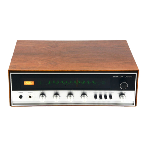
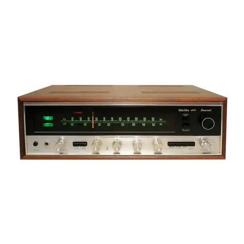
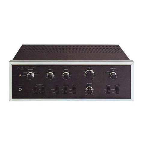
Sansui AU-6500 Troubleshooting guide

OPERATING
INSTRUCTIONS
&
SERVICE
MANUAL
_
AM/FM
STEREO
AMPLIFIER
SANSUI
AU
FE
:
LA
Ace
mea
Dine
tsb
fpr
nie
te
mete
geht
mn
6
el
NAY
at
HSL
OM
wilt
ati
FR
ca
tngmeensscrner
qt:
apathy
ea
Sm
rinrrannay
nb
ed
nA
rH
een
SESSIONS
CAFAS
TL
SANSUI
ELECTRIC
CO.,
LTD.

We
are
grateful
for
your
choice
of
the
AU-6500
Integrated
Ampli-
fier.
For
over
a
quarter
of
a
century,
Sansui
has
been
building
hi-fi
audio
equipment,
and
nothing
else.
Our
mission
is
very
old
and
at
once
ever
new
to
us:
to
bring
the
reproduced
sound
closer
and
closer
to
the
original.
The
AU-6500
now
in
your
hands
is
one
answer
from
us
to
this
never-ending
quest.
It
is
a
product
of
the
cream
of
sophisticated
modern
audio-electronics
knowhow,
coupled
with
our
long
experi-
ence,
and
as
such,
we
present
it
to
you
with
our
full
confidence.
The
AU-6500
is
a
new
breed
of
Sansui’s
AU
series
integrated
amplifiers.
Its
tone
quality
has
been
polished
and
perfected
through
an
unprecedented
number
of
listening
tests
in
different
acoustic
environments.
We
feel
certain
that
you
will
like
it,
but
you
will
find
this
out
as
soon
as
you
play
your
first
record
through
it.
This
manual
has
been
prepared
to
guide
you
in
operating
and
caring
for
the
amplifier
correctly,
so
that
you
will
get
the
most
out
of
its
built-in
high
performance
and
exceptional
versatility.
May
we
suggest
that
you
read
it
once
carefully?
CONTENTS
SWITCHES
AND
CON
TROLS
sccescedoocsctireacaccsunmdanieee
ae
Oye
SETTING
UP
YOUR
AU-6500/
|
OPERATING
PROCEDURE
............
Eb
eamitneneteenotaiei
5,
6
RECORDING
AND
PLAYBACK
BY
TAPE
DECK
...............
7
UPGRADING
YOUR
STEREO
(4-CHANNEL
STEREO
SYSTEM/ELECTRONIC
CROSSOVER
SYSTEM)
......
8
SIMPLE
MAINTENANCE
HINTS/ACCESSORY
LIST......
9,10
QUICK
CHECK
LIST
OF
SIMPLE
MISTAKES..........0..0004,
1
SPECIFICATIONS:
cuasaiasirssumtucttues
cen
taduemencsatagateaneea
sti:
12
SCHEMATIC
DIAGRAM
........
eee.
err
ee
P34
NOTES
TO
SERVICE
ENGINEERS
ccsareessestetetatentaeeuseus
15
GENERAL
TROUBLESHOOTING
CHART
.......
cee
16
DISASSEMBLY
PROCEDURE:
Ss
.cannctuiscitsaticanenintimeicats
17
PTE
ING
aa
ats
cestoctersen
ears
spr
rors
eoeestoe
aah
acai
aee
18
PRINTED
CIRCUIT
BOARDS
AND
PARTS
LIST.........
19~24
OTHER
PARTS
AND
THEIR
POSITION
ON
CHASSIS...
25,
26

VOLUME
Sansai
StenEC
AMPLIFIER
Aue
SPEAKERS
4-CH
TAPE
ALAPTOR
MONITOR
BUTIRNG
LOUDNESS
MODE
LA
RII
I
LIISA
LALA
IOLA
IRL
ALESIS
ALIA
BE
HT

SWITCHES
AND
CONTROLS
Power
Indicator
.
Lights
when
you
turn
on
the
Power/Speakers
Switch,
and
remains
lit
until
you
turn
off
the
switch.
Power/Speakers
Switch
Controls
both
the
power
supply
and
selection
of
speaker
systems.
|
POWER
OFF:
Cuts
off
power
supply
for
the
amplifier.
A:
Turns
on
power
supply
and
energizes
the
speaker
systems
connected
toSYSTEM-A
speaker
terminals
on
the
rear.
|
Because
of
the
built-in
amplifier/speaker
protec-
tion
circuit,
sound
will
come
out
with
a
delay
of
a
few
seconds.
B:
Energizes
speaker
systems
connected
to
SYSTEM-B
speaker
terminals.
A+B:
Energizes
both
A
and
B
pairs
of
speaker
systems.
SPKR
OFF:
Cuts
off
the
sound
from
all
speaker
systems
to
permit
private
listening
with
head-
phones
connected
to
the
Headphone
Jack.
Headphone
Jack
Plug
stereo
headphones
into
this
jack
for
private
listening
or
monitoring,
but
be
sure
to
turn
the
Power/Speakers
Switch
to
SPKR
OFF
first
unless
someone
is
listening
to
the
sound
from
speaker
systems
in
another
room.
The
jack
will
accept
any
standard
stereo
phone
plug,
but
for
best
tone
quality,
we
recommend
a
dynamic
type
such
as
the
Sansui
SS-20
or
SS-10.
Filters
,
Low:
Push
down
to
IN
to
eliminate
low-fre-
quency
noise
such
as
the
rumbling
of
your
turn-
table
motor.
If
no
such
noise
is
present,
be
sure
to
keep
it
off.
High:
Push
down
to
IN
to
eliminate
high-fre-
quency
noise
such
as
the
surface
noise
from
a
worn
record
or
as
the
fluorescent
lamp
noise
mixed
in
radio
broadcasts.
Tone
Controls
Let
you
tailor
the
tone
quality
of
reproduced
sound
to
your
taste
by
adjusting
the
amplifier’s
frequency
response
curve.
The
Bass
Control
is
for
adjust-
ing
the
loudness
of
bass
notes
as
may
be
produced
by
a
bass,
and
the
Treble
one
for
adjusting
that
of
treble
notes
as
may
be
produced
by
cymbals.
—
Muting
Switch
Reduces
the
sound
volume
by
20dB
at
once
with-
out
the
use
of
the
Volume
Control.
Most
con-
venient
to
lower
the
sound
volume
temporarily
when
the
telephone
rings,
to
avoid
the
noise
of
the
pickup
stylus
descending
on
a
record,
etc.

Balance
Control
Push
down
the
Mode
Switch
to
MONO
once
and
adjust
this
control
for
equal
sound
volume
from
the
left
and
right
speaker
systems,
then
return
the
switch
to
STEREO.
If
there
is
a
large
dif-
ference
in
the
sound
volumes
from
the
two
speak-
er
systems
even
with
this
control
set
near
the
center,
it
may
be
because
the
left
and
right
output
signal
levels
from
the
program
source
component
(turntable,
tuner,
tape
deck,
etc.)
are
different.
Check
the
component
once.
__-
Mode
Switch
The
STEREO
position
is
normal.
If
you
connect
a
monophonic
signal
to
either
left
or
right
input
terminal,
it
is
heard
from
both
speaker
systems
by
pushing
down
to
MONO.
——
Loudness
Switch
If
desired,
push
down
to
IN
to
emphasize
the
highs
and
lows
when
listening
at
low
volume
levels.
This
is
because
the
mechanism
of
human
hearing
is
such
that
the
high
and
low
notes
seem
greatly
enfeebled
at
low
listening
levels.
Velanie
Control
Selector
Control
Turn
to
an
appropriate
position
to
hear
the
de-
sired
program
source.
PHONO-2,
PHONO-1:
To
play
records
on
a
turntable
connected
to
the
PHONO
2
or
1
termi-
nals
on
the
rear.
TUNER:
To
hear
a
aid:
broadcast
from
a
tuner
connected
to
the
TUNER
terminals
on
the
rear.
AUX:
To
reproduce
whatever
program
source
1s
connected
to
the
AUX
terminals
on
the
rear.
(Connect
a
turntable
with
a
crystal
or
ceramic
cartridge,
the
audio
outputs
of
a
television,
the
playback
outputs
of
a
tape
recorder,
etc.
to
the
AUX
terminals.)
|
Tape
Monitor
Switch
Push
down
to
PLAYBACK
to
reproduce
a
recorded
tape
or
monitor
a
recording
as
you
make
it
on
a
tape
deck
connected
to
the
amplifier
(monitoring
is
possible
only
if
the
tape
deck
is
equipped
with
separate
recording
and
playback
heads).
Otherwise,
be
sure
to
keep
it
at
SOURCE.
4-Channel
Adaptor
Switch
If
you
connect
a
4-channel
adaptor
to
the
AU-
6500
and
make
other
necessary
connections,
you
can
upgrade
this
2-channel
stereo
amplifier
to
hear
4-channel
stereo
sound
by
pushing
this
switch
down
to
IN.
(refer
to
page
8).
Otherwise,
be
sure
to
keep
it
off.

SETTING
UP
YOUR
AU-6500/
OPERATING
PROCEDURE
GROUNDING
OF
TURNTABLE
‘2
wz
|
KAKE
)-
Gy
a
|
x
AC
OUTLETS
FOR
3
E
NT
TURNTABLE
ee
aa
nat
(With
Magnetic
Cartridge)
—
.
|
4-CHANNEL
STEREO
|
|
CONNECT
OUTPUTS
OF
SYSTEM
(SEE
PAGE
8)
AUXILIARY
COMPONENT
Ty
Clee
eun
Woe
ee
a
|
-
;
S
meme
AU
-6500
Eiwee®
STEREO
AMPLIFIER
SANSUD
ELECTRIC
ca.
tTo
PRE-MAIN
CONNECTORS
|
ELECTRONIC
CROSSOVER
SYSTEM
(SEE
PAGE
8)
RECORD
a
eee
2
|
PLAYBACK
WALL
AC
OUTLET
SPEAKER
SYSTEMS
DIN
RECORD/
PLAYBACK
CABLE
NOTE:
Do
not
connect
tape
deck(s)
to
pin
jack
terminals
and
DIN
socket
simultane-
ously.
LEFT
CHANNEL
woe
RIGHT
CHANNEL

Connecting
Speaker
Systems
If
you
are
connecting
only
one
pair
of
speaker
systems
to
the
AU-6500,
they
may
have
any
im-
pedance
from
4
to
16
ohms.
Connect
them
to
the
SYSTEM-A
or
-B
terminals
on
the
rear,
making
sure
not
to
confuse
the
left
and
right
cables,
plus
and
minus
leads
on
the
amplifier
and
speaker
ends.
But
if
you
wish
to
connect
two
pairs
of
speaker
systems
and
drive
them
simultaneously
by
turning
the
Power/Speakers
Switch
to
A+B,
each
speaker
system
should
have
impedance
of
8
to
16
ohms.
Using
a
system
with
lower
impedance
could
result
in
a
breakdown
of
the
amplifier.
Connecting
a
Turntable
Connect
it
to
the
PHONO
1
or
2
terminals
on
the
rear.
Fot
best
results,
use
a
turntable
with
a
magnetic
pickup
cartridge.
Connecting
a
Tuner
Connect
the
output
terminals
of
a
tuner
to
the
TUNER
input
terminals
on
the
amplifier’s
rear
panel.
Connecting
Grounding
Be
sure
to
connect
the
grounding
terminal
(or
lead)
of
the
turntable
and
tuner
to
the
grounding
termi-
nal
of
the
amplifier.
It
may
suppress
the
hum
noise
which
may
otherwise
occur.
PRE
MAIN
OUTPUT
INPUT
Operating
Procedure
1.
Set
the
Selector
Control
to
the
desired
program
source.
2.
Set
the
4-Channel
Adaptor
Switch
to
OUT
and
the
Tape
Monitor
Switch
to
SOURCE,
unless
you
want
to
use
them.
3.
Set
the
Power/Speakers
Switch
to
as
required.
4.
Start
the
program
source
component
and
play
the
program
source.
5.
Use
the
amplifier’s
other
controls
and
switches
to
suit
your
taste
or
room
acoustics.
Note:
To
play
a
monophonic
record
on
a
stereo
turntable,
follow
the
same
procedure
as
for
playing
a
stereo
record.
Better
results
are
normally
obtained.
|

RECORDING
AND
PLAYBACK
BY
TAPE
DECKS
Connecting
a
Tape
Deck
Connect
the
input
terminals
of
a
tape
deck
to
TAPE
REC
terminals
of
the
amplifier,
and
its
output
termi-
nals
to
the
PLAY
terminals.
The
DIN
socket
can
be
used
only
if
your
tape
deck
is
equipped
with
a
similar
socket.
It
is
manu-
factured
according
to
the
German
industrial
standard
to
permit
tape
recording
and
playback
from
a
single
cable
with
a
special
5-pin
plug
on
each
end.
Should
you
wish
to
connect
more
than
two
tape
decks,
you
may
connect
it
to
the
4-CH
ADAPTOR
terminals.
The
2-CH
OUTPUT
terminals
have
the
same
electrical
function
as
the
REC
terminals,
while
the
INPUT
terminals
are
equivalent
to
the
PLAY
terminals.
Note:
Do
not
connect
the
tape
deck(s)
to
the
pin
jack
terminals
and
DIN
socket
simultaneously.
:
es
TAPE
se
az
4-CH
ADAPTOR
2-CH
REO
YPLAY
REC
PLAY
GUTPUT
INPUT
fom
,eo200
‘9oao00d.
eek
RECORD—_.
|
PLAYBACK
DIN
RECORD/
PLAYBACK
CABLE
NOTE:
Do
not
connect
tape
deck(s)
to
pin
jack
terminals
and
DIN
socket
simultane-
wm
RIGHT
CHANNEL
ously.
===
LEFT
CHANNEL
Recording
&
Playback
Procedure
Recording
1.
Set
the
Selector
Control
to
the
program
source
you
wish
to
record.
2.
Adjust
the
recording
volume
control
of
the
tape
deck
to
preset
the
recording
level.
3.
Start
the
tape
deck
in
the
recording
mode.
4.
To
monitor
the
recording
as
you
make
it,
push
down
the
Tape
Monitor
Switch
to
PLAYBACK.
Be
sure
to
set
the
monitor
switch
of
the
tape
deck
to
the
playback
mode
as
well.
Playback
1.
Set
the
Tape
Monitor
Switch
to
PLAYBACK.
2.
Start
the
tape
deck
in
the
playback
mode.
3.
Use
the
amplifier’s
other
switches
and
controls
to
suit
your
taste
or
room
acoustics.
Procedure
for
Copying
a
Recorded
Tape
Oo
If
you
want
to
copy
a
recorded
tape,
connect
one
tape
deck
for
playback
to
the
TAPE
terminals,
the
other
for
recording
to
the
4-CH
ADAPTOR
termi-
nals.
©
By
operating
the
4-Channel
Adaptor
Switch,
you
can
monitor
the
recording
as
you
copy
it
from
one
tape
deck
to
the
other.
To
monitor
the
recording
before
it
is
copied,
keep
the
4-Channel
Adaptor
Switch
at
OUT.
To
monitor
the
recording
after
it
is
copied,
push
down
to
IN.
Notes
about
Recording
1.
Monitoring
of
recorded
sound
is
possible
only
if
the
recording
tape
deck
is
equipped
with
separate
heads
for
recording
and
playback.
Otherwise,
set
the
Tape
Monitor
Switch
to
SOURCE
and
listen
to
the
original
input
sound
before
it
is
recorded.
2.
The
various
switches
and
controls
on
the
AU-
6500
do
not
affect
the
sound
recorded
into
the
tape
deck.
They
only
adjust
the
sound
from
the
speaker
systems
or
headphones.

UPGRADING
YOUR
STEREO
4-Channel
Stereo
System
The
sound
we
hear
daily
is
a
mixture
of
the
sound
that
reaches
our
ears
straight
from
the
sound
source—be
it
a
musical
instrument,
a
jet,
a
man’s
mouth
cr
what
have
you—and
the
‘indirect
sounds’
that
arrive
at
our
earsonly
after
they
are
reflected
off
various
surfaces,
such
as
the
walls,
ceiling
and
so
forth.
Four-channel
recordings
are
made
using
two
microphones
in
the
front
of
the
concert
hall
and
two
in
the
rear
(to
simplify
the
explanation).
The
‘indirect
sounds’
with
their
complicated
waveforms
are
mainly
picked
up
by
the
two
microphones
in
the
rear,
and
reproduced
out
of
the
two
rear
speakers
in
a
4-channel
stereo
set-up
for
greatly
enhanced
‘ambience’
effects.
The
effect
is
almost
as
if
the
original
live
performance
were
re-played
right
in
your
own
room.
|
This
new
approach
can
now
be
yours
simply
by
adding
certain
equipment—mainly,
a
Sansui
4-
channel
rear
amplifier
with
its
unique
QS
(RM)
synthesizer
decoder
matrix
(patents
pending),
and
a
second
pair
of
speaker
systems—to
your
2-channel
stereo
system.
Connection
of
such
a
rear
amplifier
or
4-channel
adaptor
is
easy.
Just
connect
the
4-
CH
ADAPTOR
2-CH
OUTPUT
terminals
of
the
AU-6500
with
the
input
terminals
of
such
rear
amplifier
or
4-channel
adaptor,
then
connect
its
4-
CH
ADAPTOR
INPUT
terminals
with
the
output
terminals
of
such
unit.
To
operate
the
rear
amplifier
or
4-channel
adaptor
so
connected,
push
the
4-Channel
Adaptor
Switch
on
the
amplifier’s
front
panel,
and
otherwise
follow
its
manufacturer’s
instructions.
Electrically,
the
4-CH
ADAPTOR
2-CH
OUTPUT
and
INPUT
terminals
possess
the
some
functions
as
the
TAPE
REC
and
MON
terminals,
respectively.
4-CHANNEL
REAR
AMP.
4-CHANNEL
ADAPTOR
Electronic
Crossover
system
The
electronic
crossover
system
affords
these
ad-
vantages:
1.
It
enables
the
tweeters,
midranges
and
woofers
to
be
driven
by
separate
power
amplifiers.
So
you
can
make
optimum
use
of
speakers
of
different
im-
_
pedances
and
efficiencies,
as
well
as
power
amplifiers
of
different
output
capacities
and
tone
qualities.
2.
It
eliminates
the
need
for
the
conventional
LC
type
crossover
network.
With
the
electronic
cross-
over
divider,
the
amplifier’s
damping
factor
is
no
longer
affected
and
you
can
set
crossover
frequencies
as
you
like.
Electronic
Crossover
System
Using
the
AU-6500
The
preamplifier
and
power
amplifier
sections
of
the
AU-6500
can
be
disconnected
for
independent
usage,
the
latter
section
being
available
for
driving
a
separate
speaker
in
an
electronic
crossover
system.
To
build
such
a
system,
you
will
need
two-
or
three-
way
speaker
systems
and
an
electronic
crossover
divider,
along
with
at
least
one
or
two
additional
power
amplifiers.
Connection
is
not
all
that
difficult.
First
remove
the
Pre-Main
Connectors
uniting
the
amplifier’s
pre-
amplifier
outputs
and
main
(power)
amplifier
inputs.
Then
just
connect
the
PRE
OUTPUT
to
the
input
terminals
of
the
electronic
crossover
divider,
which
divides
the
input
signals
into
high,
medium
and
low
range(s).
Finally,
couple
the
separate
output
term1-
nals
of
the
electronic
crossover
divider
to
the
ampli-
fier’s
MAIN
INPUT
and
the
additional
power
ampli-
fier(s),
feeding
their
outputs
separately
into
in-
dividual
speakers,
as
illustrated
below.
ELECTRONIC
CROSSOVER
DIVIDER
PROGRAM
70)
8]
£69
WOOFER

SIMPLE
MAINTENANCE
HINTS
/ACCESSORY
LIST
Rear-Panel
AC
Outlets
Of
the
three
AC
outlets
provided
on
the
rear
panel,
the
ones
marked
‘SWITCHED?’
are
controlled
by
the
front-panel
Power/Speakers
Switch.
The
third
one,
marked
‘UNSWITCHED,’
is
always
‘live’
and
independent
of
the
Power/Speakers
Switch.
The
voltage
delivered
at
these
AC
outlets
is
the
same
as
the
power
supply
voltage
used.
The
two
‘SWITCHED’
outlets
have
a
total
power
capacity
of
100
VA,
while
the
UNSWITCHED
one
150VA.
Before
you
connect
any
appliance
to
them,
be
sure
that
it
is
adjusted
for
use
at
the
same
power
supply
voltage,
and
that
its
power
consumption
is
not
beyond
these
figures.
Otherwise,
serious
danger
could
result.
Make
Proper
Connections
Connect
the
loadwires
of
speaker
cables
properly.
If
they
are
loose
or
touch
other
parts,
the
amplifier
may
produce
noise
and
eventually
break
down.
Also,
before
connecting
a
turntable,
tuner
and/or
tape
deck,
be
sure
to
read
their
manufacturers’
instructions.
CONNECTING
SHIELDED
CABLE
TO
A
PIN
PLUG
(l)
REMOVE
PIN
PLUG
COVER
4
PIN
PLUG
({7//LLA
CCC
WS
SANS
PIN
JACK
a
it
~
i
SEWER
=
ye
:
CUT
OFF
EXCESS
a.
aN
Speaker
Impedance
Do
not
ever
connect
two
pairs
of
speaker
systems
with
impedance
of
less
than
8
ohms
each.
Doing
so
will
reduce
the
composite
speaker
impedance
in
each
channel
to
less
than
4
ohms,
and
may
cause
the
quick-acting
fuses
to
blow
or
result
in
a
more
serious
breakdowns
over
a
long
period
of
time.
Phasing
of
Speakers
Listen
to
any
monophonic
reproduction.
If
the
speak-
er
systems
are
correctly
phased,
the
sound
will
seem
to
come
from
a
point
midway
between
the
left
and
right
speaker
systems.
If
the
sound
is
not
directly
in
front
of
you,
however,
the
speaker
systems
are
out
of
phase.
If
you
notice
this
condition,
check
the
speaker
connections
once.
To
correct
the
condition,
switch
the
amplifier
off
and
reverse
the
connection
of
plus
and
minus
leadwires
of
one
speaker
cable.
Also,
be
careful
not
to
connect
a
single
speaker
system
between
the
SYSTEM-A
and
SYSTEM-B
terminals
by
mistake.
Howling
and
Hum
Take
care
never
to
place
a
turntable
on
or
too
near
a
speaker
system,
or
the
vibration
produced
by
the
speaker
system
is
transmitted
and
causes
an
oscillat-
ing
phenomenon
called
howling.
It
is
best
to
keep
these
components
completely
separated,
but
if
this
is
impossible,
place
a
thick
cushion
between
them.
Humming,
in
contrast,
is
a
phenomenon
caused
by
incomplete
or
incorrect
turntable-amplifier
connect-
tions.
Should
this
occcur,
check
to
see
if
all
con-
nections
are
completely
made
and
if
the
connecting
cables
are
sufficiently
thick.
Hum
noise
may
some-
times
be
eliminated
by
connecting
the
grounding
lead
of
the
turntable
to
the
GND
terminal
on
the
amplifier’s
rear.

Voltage
Adjustment
Your
AU-6500
is
adjusted
to
operate
at
the
correct
power
supply
voltage
of
your
area
prior
to
shipment
from
our
factory.
If
you
move
after
purchasing
it
or
send
it
as
a
gift
to
a
friend
living
in
an
area
where
the
voltage
is
different,
it
may
be
necessary
to
adjust
its
Voltage
Selector.
To
adjust
it,
remove
the
two
screws
securing
the
name
plate
on
the
rear,
then
set
the
arrow
mark
on
the
Voltage
Selector
Plug
to
the
correct
voltage
indication
(100,
117,
220,
or
240
volts).
Also,
it
may
by
necessary
to
replace
the
power
fuse
as
will
whenevr
the
voltage
has
changed.
For
opera-
tion
at
100—117
volts,
use
a
3-ampere
fuse.
For
operation
at
220—240
volts,
use
a
2-ampere
one.
CAD
emmmene
omen
VT
220V——-
i
IOOV
240V
Ti7v
ae:
‘©
J20V
TOOV
220V
(2A)
240Van
117V
Ct
|
©)
220V
T00V
240V
(2A)
Heat
Radiated
inside
the
Amplifier
The
bonnet
of
the
AU-6500
is
designed
so
that
any
heat
radiated
inside
will
effectively
escape
through
it.
Proper
care
should
therefore
be
taken
of
the
dissipation
of
such
heat
if
you
wish
to
place
some-
thing
on
top
of
the
amplifier
or
place
it
inside
a
closed
box,
etc.
Above
all,
avoid
placing
it
where
it
may
be
exposed
to
the
direct
sunlight.
It
is
prohibited,
however,
to
remove
the
amplifier’s
bonnet
or
bottom
plate
to
improve
the
ventilation.
Accessory
List
1.
OPERATING
INSTRUCTIONS
AND
SERVICE
MANUAL
.......0..-0
008%
1
2.
OPERATING
INSTRUCTIONS
SHEET
....
1
3.
PIN
PLUGS
sachs
cetwacciaemekneaeee
notes
4
As
BUTTERELY
BOLTS
scicnsiiactsavedoek
2
Bu,
WASHERS
ccaccavensidnacnaunedaucdennwes
2
6.
POLISHING
CLOTH...........0
cece
eens
1
7.
QUICK-ACTING
FUSES
(3A)........2
00ers
2
4G
4

QUICK
CHECK
LIST
OF
SIMPLE
MISTAKES
Some
of
the
troubles
which
seem
to
result
from
a
malfunction
of
the
amplifier
are
caused
by
wrong
operation
and
the
negligence
of
simple
maintenance,
and
can
be
quickly
corrected
by
making
a
simple
investigation
and
providing
simple
cures.
To
make
sure
you
haven’t
made
any
of
these
mistakes,
go
over
the
following
check
list
once.
Connections
1.
Have
you
connected
the
power
cord
to
a
wall
AC
outlet
?
O
2.
Are
the
connecting
cables
for
the
turntable
and
tape
deck
not
loose
?
|
3.
Are
the
speaker
cables
not
loose
from
amplifier’s
jacks
or
the
speaker
systems?
4.
Do
your
speaker
systems
have
impedance
of
8
ohms
more?
(They
must,
if
you
wait
to
drive
two
pairs
at
one
time.)
5.
Have
the
power
fuse
or
quick-acting
fuses
not
blown?
Operating
Procedure
1.
Have
you
turned
on
the
Power/Speakers
Switch?
2.
Is
the
Tape
Monitor
Switch
not
set
to
PLAY-
BACK
position,
though
you
don’t
want
to
reproduce
a
tape?
|
3.
Is
the
Selector
Control
set
to
the
correct
position?
4.
Is
the
Power/Speakers
Switch
set
to
the
correct
position
?
5.
Is
the
4-Channel
Adaptor
Switch
not
pushed
down,
though
you
are
not
using
a
4-channel
rear
amplifier
or
adaptor
?
If,
even
after
these
examinations,
the
amplifier
does
not
return
to
normal,
it
may
be
faulty.
Contact
the
Sansui
dealer
from
whom
you
purchased
the
am-
plifier
or
your
nearest
Sansui
Authorized
Service
Station.
Do
not
attempt
opening
the
bonnet
for
yourself.
Such
repair
must
be
left
to
a
qualified
serviceman.
Should
the
Power
Fuse
Blow
If
no
Power
Indicator
should
glow
and
the
ampli-
fier
simply
remains
dead
even
after
you
have
turned
on
its
power
fuse
has
blown.
If
this
happens,
dis-
connect
the
power
cord
from
the
wall
AC
outlet
at
once
and
examine
the
power
fuse
on
the
rear
panel.
If
you
find
it
blown,
replace
it
with
a
new
glass-
tubed
fuse
of
the
rated
capacity
(3-ampere
for
100
‘to
117
volts,
2-ampere
for
220
to
240
volts).
Never
use
a
fuse
of
a
different
capacity
or
a
piece
of
wire,
even
as
a
stop-gap
measure,
or
serious
danger
could
result.
Reploce
with
same
type
3A-250V
fuse
ot
100/117¥
2A-250V
fuse
at
220/240V
Vane
on
ve
%
%
«
is
%
te
y
_"
Quick-Acting
Fuses
The
AU-6500
is
doubly
protected
with
a.
relay-
equipped
protection
circuit
and
four
quick-acting
fuses.
If
no
sound
or
distorted
sound
is
heard
from
either
or
both
speaker
systems,
switch
off
the
ampli-
fier,
disconnect
the
power
cord
from
the
wall
AC
outlet,
remove
the
cover
on
the
rear
panel
conceal-
ing
the
quick-acting
fuses
and
examine
them.
If
you
find
any
of
them
blown,
find
and
eliminate
the
cause
of
the
blowout,
then
replace
it
with
a
new
glass-tubed
quick-acting
fuse
supplied.
If
the
relay-equipped
protection
circuit
ever
goes
to
work,
the
sound
may
come
out
intermittently.
If
it
happens,
check
the
connections
of
various
equip-
ment
and
your
operating
procedure
once.
es
|

SPECIFICATIONS
QC,
eGO"“_—_—
POWER
OUTPUT
SWITCHES
&
CONTROLS
IHF
MUSIC
POWER:
94W
(4)
at
1,000Hz
BASS:
+15dB,
—15dB
at
50Hz
CONTINUOUS
RMS
POWER
TREBLE:
+.
15dB,
—15dB
at
15,000Hz
(each
channel
driven):
—
32/32W
(8Q)
at
1,000Hz
LOUDNESS:
+10dB
at
ne
+
8dB
-
|
CONTINUOUS
RMS
POWER
|
aes
Mee
ween
,000H
~<
:
Demy
erenis
®
ee
aya
araen
ver
a
LOW
FILTER:
—12dB
at
50Hz
(6dB/oct)
TTR
HARMONIG
cia
;
HIGH
FILTER:
_12dB
at
10,000Hz
(6dB/oct)
ee
SEMICONDUCTOR:
transistors;
35
diodes;
6
INTERMODULATION
DISTORTION
(70Hz:7
,QOOOHz
=4:1
SMPTE
method):
less
than
0.1%
at
rated
output
IHF
POWER
BANDWIDTH
POWER
REQUIREMENTS:
100,
117,
220,
240V
50/60Hz
POWER
CONSUMPTION
(each
channel
driven
at
8Q)):
ee
—
5
to
40,000Hz
:
a
FREQUENCY
RESPONSE
(at
1Watt
power
outpnt)
DIMENSIONS:
po
i
Aan
PHONO-1
and
2:
RIAA
equalization
curve
322mm
(1
2y,")
D
+0.5dB
(30
to
15,000Hz)
AUX:
10
to
30,000Hz
+1.0dB
WEIGHT:
11.5kg
(25.3
Ibs)
MAIN
INPUT:
10
to
40,000Hz
+1.0dB
LOAD
IMPEDANCE:
4
to
160,
DAMPING
FACTOR:
approximately
40
at
822
load
INPUT
SENSITIVITY
AND
IMPEDANCE
(at
1,Q00HZz)
PHONO-1:
2.5mV
(50kQ)
PHONO-2:
2:5mV
(50k)
(Maximum
input
capability
300mV
THD
:
less
than
0.5%)
TUNER:
100mV
(50kQ)
AUX:
100mV
(50kQ))
TAPE
PLAY
(Pin):
100mV
(50kQ))
TAPE
REC/PLAY
(DID):
=
100mV
(50kQ))
4-CH
ADAPTOR:
100mV
(50kQ)
MAIN
INPUT:
g00mV
(40kQ)
OUTPUT
VOLTAGE(at
1,000HZz)
TAPE
REC
(Pin):
100mV
TAPE
REG/PLAY
(DIN):
30mv
4-CH
ADAPTOR:
100mV
PRE
OUTPUT:
0.8V
(THD:
less
than
0.08%)
(Maximum
Output
Voltage
4.0V
THD:
less
than
0.5%)
CROSSTALK
(at
rated
output,
1,000HZz):
PHONO-1:
better
than
50dB
PHONO-2:
better
than
50dB
TUNER:
better
than
50dB
AUX:
.
better
than
50dB
MAIN
INPUT:
better
than
50dB
IHF
HUM
AND
NOISE
PHONO-1:
-
better
than
70dB
PHONO-2:
|
better
than
70dB
TUNER:
|
better
than
80dB
AUX:
|
better
than
80dB
MAIN
INPUT:
_
better
than
100dB
—
ess
{Oe

SCHEMATIC
DIAGR
F-2028-A
TReo1
7
2s.
0
TReog
A493GR
2SCIOOOGR
Cso1
0.047
Reos
120K
G
PHONO
|
r
4
aes
60
O
PHON,
O
S
ts
TUNER
|
O
S3a
6
~~
~
AUX
x
S
.
()
[REC
€
(
TAPE
|
aay
Re35
27K
—
Rea
560K
OUT
4CH
ADAPTOR
|
L
ww
!
aly
|
&
PHONO
|!
,
|
3
4
2
602
©)
PHONO
2
(0
oe
Sy
d
8
oe
TUNER
©)
G
AUX
r
REC
|
TAPE
Le
pay
OUT
4CH
ADAPTOR
IN
S;
(a~d)
SELECTOR
SW
57
(a,b)
HIGH
FILTER
SW
1.
PHONO
2
1.
OUT
2.
PHONO
|
2.
IN
3.
TUNER
4,
AUX
Sg
(a,b)
LOW
FILTER
SW
1.
OUT
Sp
(a,b)
TAPE
MONITOR
SW
2.
IN
1.
SOURCE
2.
PLAY
BACK
Sg
(a~e)
POWER
SW
1.
POWER
OFF
S3
(a,b)
4CH
ADAPTOR
SW
2.
POWER
ON
SPSYSTEM
A
1.
OUT
3.
4
SP.
SYSTEM
B
UNSWITCHED
x]
Foor
5)
2.
IN
4,
”
SP.
SYSTEM
A+B
SWITCHED
x2
100~117
5.
”
SP
SYSTEM
OFF
220~240V
2h
Sq
MODE
SW
1.
STEREO
2,
MONO
Ss
(a,b)
MUTING
SW
VRno3.706
+
=MASTER
1.
NORMAL
Vide
ae
BASS
25
2,
-20dB
Vows
-icn
TREBLE
GRA
Ss
(a,b)
LOUDNESS
SW
Re
1.
OUT
CAPACITORS
P
.
oO
OIL
:
07
oe
&
CERAMIC
Do
BLUE
ie
©
MYLAR
Plisgi
9
:
;
®
STYROL
63v
BOnke)
*/A
0.
s
ome
.
BLUE
ys
BLACK
Xwered-tn
Fuse.
2549
2-4

TR293
TRros
*TR107
I3GR
2SCIOOOGR
2SA493GR
x2
723
=f
-
7R
TRe0s
7Re07
iT
803
2SDi88
:
al
gor
LF
ao
Al
acidSscr
2sciiza
28C28l
seach?
.
SS
5
1
2SA493GR
|
“s
&
1
s§
|
x
S
Hf
g
1)
%
pi
c&
3
&
S
&
S
bs
:
&
.
S
:
38
3
ah
&
€
&S
5
8
=
{D>
2
¥
2
[|
,
8
e"
ie
_
:
g
5S
8
8
3
SS
i
wd
Z
ma)
6],
20
703\
SS
To
_
713
i
=
gla&
EL
a
1O=—@
O02
1Q_9—O2
OE
VRaos
10OK(B)
Vay
TOOK(W)
on
e.
TRe1s
l
is
TREBLE
HIGH
FILTER
LOW
FILTER
IS1555
x2
2SA627
i
|
Base
TREBLE
HIGH
FILTER
LOW
FILTER
3
'
|
VRra6
VRa0g
See.
{Dap
TReoa
=
T
Reno
eae
i
a
ne
®
é
O
=
O
9
a
=
02
S
w
Hl
9
Jea1
°
BF
|
neaDPHONes
[r™
O°
eo
S
1,0
“4
B;
Bo
By
Ba
&
&
|
ae
>
|
f
©
LEFT
a}
of
S|
S
eS
O5
al
8
"3,
2
SYSTEM
A
sg
gg
o
4
|
’
RIGHT-
0
O O
0
l
Y
62
3
O
|
4
SB2
ay
-31V
ee
=
|
O1
+
5
SX
i
a
-TS8
aN
2
LEFT
Ss
S
Qe
+
w&B
Re
5
4
&s
SS
SYSTEM
B
RIGHT:
~
*[F-2041
TReo1
TRo02
2SC634A
2SC634A
O-0
_
“SAV
G
YRoo22K
OD)
|
TRoor
|
VEYOF
=
Rap
Rog
150(%e)
5602)
OT
"SPEAKERS
|
OF
F-1215-A]
|
Dix4
IRI
br
Y
|
Thay
@SCESAATS,
6)
S
<
Nf)
t
Bes
Ob
4S
8
aL
Owe
|
Sie
e
=
ye!
g
S
.
&
:
Fe
|
TRoo2,
003
2Doo1
13-1
2SA678
«=
ZB-
I-14
5
zs
ed
INS4A(K)
x4
a
A
cs

NOTES
TO
SERVICE
ENGINEERS
MM
Please
-contact
the
nearest
Sansui
Authorized
Service
Station
for
replacement
parts.
When
order-
ing
them,
look
up
the
part
lists
on
pages
19
to
26
and
let
us
know
(1)
the
amplifier’s
model
number,
2)
name
of
the
printed
circuit
board,
(3)
part
No.,
(4)
name
of
the
part,
and
(5)
its
stock
No.
Using
nonstandard
parts
for
temporary
relief
often
impairs
the
sound
quality
and
over-all
reliability
of
the
amplifier.
Please
take
the
trouble
to
contact
your
nearest
Sansui
Authorized
Service
Station.
Mi
Consult
pages
17
to
26
when
making
repairs
or
adjustments.
To
check
or
measure
the
amplifier
performance,
connect
load
resistance
of
4
to
16
ohms
to
the
amplifier’s
speaker
output
terminals
first.
To
check
the
electrical
output
characteristics,
do
not
remove
the
bonnet
and
bottom
plate.

GENERAL
TROUBLESHOOTING
CHART
PROGRAM
SOURCE
SYMPTOM
PROBABLE
CAUSE
|
WHAT
TO
DO
Tuner.
*
Noise
during
AM
recep-
|
*
Interference
by
adjacent
sta-
|
*
Peculiar
to
AM
waves,
and
unavoid-
tion.
tions
(called
beat
interfer-
able
to
some
extent.
ence).
*
TV
set
is
being
used
simul-
|
*
Move
TV
set
away
from
tuner
and
taneously.
amplifier.
Noise
heard
at
certain
|
*
Interference
by
nearby
elect-
|
*
Attach
noise
limiter
to
appliance
hours,
in
certain
areas
rical
appliances.
producing
noise.
oe
over
part
of
dial
*
In
some
cases,
can
be
eliminated
by
uring
AM
reception.
reversing
power
cord
plug-AC
outlet
connections.
Pop
noise
during
FM
|
*
Ignition
noise
from
nearby
|
*
Adjust
antenna
location
and
height
reception.
automobile,
motorcycle,
etc.
for
maximum
sensitivity.
*
Keep
antenna
away
from
streets.
Note:
In
many
cases,
high-frequency
noise
during
radio
reception
cannot
be
entirely
eliminated.
Try
turning
on
amplifier’s
High
Filter
Switch
or
turning
Treble
Control
counterclockwise.
Turntable.
Hum
noise.
*
Unshielded
cables
used
to
|
*
Use
regular
shielded
cables.
connect
turntable.
*
Examine
connecting
cables,
especial-
*
Minus
(ground)
wire
of
con-
ly
their
plugs.
stones
a
1s
not
connect-
|
*
Connect
grounding
lead
of
turntable
ea
completely.
to
amplifier’s
GND
terminal.
*
Turntable
motor
or
tonearm
is
not
grounded.
Loud
oscillating
noise.
*
Turntable
is
placed
on
top
|
*
Place
thick
cushion
between
turntable
of
or
too
close
to
speaker
and
speaker
systems.
systems.
*
Change
location
of
turntable
and
speaker
systems.
*
If
using
microphone(s),
move
or
direct
them
away
from
speaker
systems
Sound
is
shaky.
*
Dust
on
record
or
pickup
|
*
Clean
record
and
pickup
stylus.
7
stylus.
-*
Replace
pickup
stylus.
*
Worn
pickup
stylus.
*
Adjust
stylus
pressure.
*
Improper
stylus
pressure.
Tape
Deck.
Hiss
noise.
*
Magnetic
heads
are
magnet-
|
*
Demagnetize
heads.
ized.
*
Turn
on
High
Filter
Switch.
*
Connect
noise
reduction
adaptor.
Sound
is
not
clear.
*
Dust
on
magnetic
heads.
*
Clean
heads.
*
Tape
is
not
pressed
tight
to
|
*
Align
tape
transport
mechanism.
heads.
7
General.
When
left
and
right
|
*
Left
and
right
channel
|
*
Never
mind.
Optimum
stereo
effect
channel
sound
volumes
are
balanced
with
ampli-
fier’s
Balance
Control,
it
does
not
come
to
center
position.
Musical
and
singer
not
located
clearly.
Want
to
listen
at
very
low
volume
level
at
night.
instruments
*
is
obtained
by
adjusting
Balatice
Control
so
that
sound
comes
from
Left
and
right
speaker
sys-
midway
point
between
two
speaker
tems
have
different
efficien-
systems
with
Mode
Switch
set
to
cies.
MONO.
signal
strengths
vary
with
program
source.
Left-right,
plus-minus
con-
|
*
Examine
connections
once.
nections
of
speaker
systems,
input
cables
are
wrong.
*
Turn
on
Muting
Switch,
then
adjust
Volume
Control.
Fine
adjustment
of
very
low
volume
cannot
be
done
with
Volume
Control.
2416
2

DISASSEMBLY
PROCEDURE
=
Lid
Zz
z
.o)
a
=)
<
he
ve)
=
SCREW
BOTTOM
PLATE
FRONT
PANEL
Sees
by
oe

ALIGNMENT
Output
of
Power
Amplifier
Current
Alignment
of
Power
Section
Amplifier
Section
STEP
CONNECT/ADJUST
REMARKS
step
|AMMETER|
CONNECT/ADJUST
[REMARKS
(TESTER)
1.
Remove
Foo.
and
Foo.
|
Use
1.
|
Connect
load
resistance
(8
ee
ene
ee
to
16
ohms)
to
left
(right)
2.
Turn
VRgo3
and
VRgox
|v.
channel
SYSTEM-A
fully
eaunterelociewise:
laa
speancraceminal:
3.
Turn
Power/Speakers
|
range.
Switch
to
SPKR
OFF.
Set
to
Connect
ammeter
100mA
where
Fo92
was.
(Con-
3.
|
Turn
Power/Speakers
?
range.
nect
(21)
on
schematic
|
Swith
to
SYSTEM-A.
,
2
to
minus
terminal
of
ammeter,
other
end
to
4.
Adjust
VRgo:
(VRgo2)
so
plus
terminal.)
that
voltmeter
indicates
5
Adjust
VRene
(left
chan-
0+50mA.
Repeat
above
eels
SO
that
Nee
procedure
for
right
chan-
‘nadicates
O08
to
Som
A
nel
(notations
in
parenthe-
ses
are
for
right
channel).
6.
Turn
off
Power/Speak-
|
ers
Switch
and
replace
Foo2
:
7.
|
Set
to
Turn
Power/Speakers
100mA
Switch
to
SPKR
OFF,
range.
then
connect
ammeter
where
Fo93
was.
(Con-
nect
(22)
on
circuit
schematic
to
minus
ter-
minal
of
ammeter,
other
end
to
plus
ter-
minal.)
8
.
Adjust
VReos
(right
channel)
so
that
am-
meter
indicates
28
to
32mA.
9.
Turn
off
Power/Speak-
ers
Switch
and
replace
Foos.
2.
|
Connect
voltmeter
in
par-
|
Set
voltmeter
to
allel
with
load
resistance.
|
0.5V~3V
range.
>
VR803
VR804
VR801-

PRINTED
CIRCUIT
BOARDS
AND
PARTS
LIST
W:
Parts
No.
X:
Parts
Name
Y:
Stock
No.
Z:
Position
of
Parts
DRIVER
BLOCK
<F-2034-A>
Stock
No.
7570680
w
|
x
|
y
|
z
w
|
x
oy
|
z
Reot
150k
0101154
|
2B
VRe03
1k
Q(B)
(Left)
1035070
|
1A,
B
Reo2
150kQ
0101154
|
2B
VR804
era
De
Wasnt:
(Right)}
1035070/18,C
Rso3
10kQ
0101103
|
2B
R804
10kQ,
.
0101103
|
2B
Cso1
ee
nye
0519101
|
2B
R805
47kQ
0101473
|
2A
C802
1
LF
;
0519101
|
2B
R806
A7kQ
0101473
|
2c
C803
pees
10%
s0V
cc
0660101
|
2B
R807
18kO
0101183
|
2A,
B
C804
100pF
0660101
|
2B
R808
18kQ
0101183
|
2B,C
C805
pees
ee
0515470
|
2A
Rso9
18kO,
0101183
|
2A
Cs06
47
uF
.
0515470
|
2C
R810
18kO
0101183
|
2c
C807
om
‘oy,
BEES
0531470
|
2A
Rat
3.3kQ
0101332
|
2A
Ceos
47
uF
0531470
|
2C
Rai2
3.3kQ
0101332
|
2C
Caos
PF
10
eis
ae
0660100
|
1A
Rei3
39.0,
0101390
|
2A
Cai0
10pF
0660100
|}
1C
R814
390
0101390
|
2C
Cait
yal
SOV
EC
0515470
|
1A
Rais
39
0101390
|
2A
Cai2
47
pF
0515470
|
1C
Raié
390,
0101390
|
2C
C813
0.
ont
Be
eau
We
0601477
|
1A
Rei7
18kQ,
0101183
|
2A
Cal4
0.047
uF
0601477
|
1C
Reis
18kQ,
0101183
|
2C
C815
aa
she
cee
0515101
|
1,2A
Reis
1.8kQ
0101182
|
2A
C816
100/HF
0515101
|
1,2C
Re20
1.8k0,
0101182
|
2C
C817
sn
Nee
eae
eG
0660220
|
2B
Rea
39kQ,
0101393
|
1,2A
Cais
22pF
0660220
|
2B
Rez2
39kO,
0101393
|
1,2C
Cai9
sal
sas
cee.
0510221
|
2B
Re23
220k0.
|
1994
YN
CR
0101224
|
1,2A
C820
220
uF
0510221
|
2B
Reo
220k0,
(
~
0101224
|
1,2C
Ce2r
|
a
an
ee
0515101
|
1,28
R825
—3.3k0,
0101332
|
2A
C822
—
1004F
0515101
|
1,28
R826
3.3k
0101332
|
2C
Rez
aa
0101103
|
1,2A
TReoi
0300450
|
2B
Re2s
10kQ,
0101103
|
1,2C
TR802
|
|
95,4493
(GR)
Seas
Naas
Re29
4.7kQ
0101472
|
1,2A
TRe03
0300450
|
2A
Reso
4.7kO,
0101472
|
1,2C
TRe04
0300450
|
2C
tm
|
win
ors)
|
28
rag
|
eva
oe
Rese
1800,
0101181
|
2B
Ra33
8200,
|
0101821
|
1B
TReo7
25C281
(B,
C)
0305121,
2;
1A
Res4
8200,
0101821
|
1B
TRe08
0305121,
2
|
10
Ress
3.3k0,
0101332
|
2A,
B
oe
25C959
(L,
M)
poe
:
Re36
3.3kQ,
0101332
|
2B,
C
Reaz
390,
0101390
|
1A
TRe11
25,4606
(L,
M)
0300211,
2
|
18
Ress
39.0
0101390
|
1C
TRei2
0300211,
2)
15
R39
1800,
0101181
|
1A
we
Sayi040
|
BA
Redo
1802,
0101181
|
1C
Sas
nase
(De
he
ten
ser
aL
Dg03
ree
0311040
|
2A
Re42
22029
0101221
|
1C
a
aanioael
ae
Res)
2200)
|
Adee
a
tid
Printed
Circuit
Board
F-2034
2570460
Res4
2202
0101221
|
1B,C
)
Re45
1.5kQ
|
0101152
|
1B
Ras6
1.5kQ
0101152]
1B
R8si
Pee
0%
IW
CR
0104100
|
1A
Re52
100
0104100
|
1C
R847
100
0101100
|
1A
Rs48
100
0101100
|
1C
Reso
a
Oe
aN
ER
0101100
|
1B
Reso
|
109
0101100
|
1B
VReo1
|
4.7kQ(B)
(Left)|
1035110
|
2A
VReo2
fae
AC
Balance
Adi.
(a:
ity}
1035110
|
2C
—
19
——
Other manuals for AU-6500
1
Table of contents
Other Sansui Amplifier manuals

Sansui
Sansui AU-111 Troubleshooting guide

Sansui
Sansui 5000X User manual

Sansui
Sansui AU-G99X User manual

Sansui
Sansui AU-999 Troubleshooting guide

Sansui
Sansui 3000 User manual

Sansui
Sansui AU-101 Troubleshooting guide

Sansui
Sansui EIGHT User manual

Sansui
Sansui BA-5000 User manual

Sansui
Sansui C-1000 User manual

Sansui
Sansui A-9 User manual

Sansui
Sansui AU-517 User manual

Sansui
Sansui AU-5500 User manual

Sansui
Sansui AU-D11 II User manual

Sansui
Sansui 2000A User manual

Sansui
Sansui 2000X User manual

Sansui
Sansui AU-X201 User manual

Sansui
Sansui SAP201V User manual

Sansui
Sansui AU-X701 User manual

Sansui
Sansui B-3000 User manual

Sansui
Sansui AU-777A Troubleshooting guide