−1−
• Read through the instruction manual of LCR700 too, and
use the instrument c orrectly and safely.
• The product and this manual are subje ct to change a
part of the appearance and/or specifications without
prior notice.
• This p roduct wor ks with a PC (Personal Computer).
• Please note that we are not responsible for any outcome
of the operation of the product.
1-1 LCR-USB Disc
The disc (CD-ROM) in cludes an installer of the LCR soft ware
and a devi ce driver for the USB communication.
Contents Folder and Äle names Description
Installer application
\App\setup.exe
Device driver
\Driver\Vista_7 32 bit 64 bit For W indows7 32 bit / 64 bit
and Vista 32 bit
\Driver\XP 32bit For Windows XP
1-2 System Requirements
CPU: 1.6 GHz or faster RAM: 1 GB or more
Supported OS : Windows XP*
ConÄrmed OS : Windows Vista 32 bit,
Windows 7 32 bit/64 bit
* In the case of Windows XP, Microsoft .NET Framewo rk2.0
or above ha s to be installed in advance. Other wise, visit
Microsoft Download Center to install the .NET Framework.
• Microsoft and Windows are registered trademarks of US
Microsoft Corporation in the USA and other countries. The
other company names and product names in this manual are
registered trademarks or brands of each company.
1-3 Content s
LCR-USB Disc (Installer appli cation for LCRLink software and
Device driver for LCR-USB), LCR-USB, and Instruction manual
[1] SAFETY PRECAUTIONS
– Before use, read the following safety p recautions.–
This instruction manual explains how to safely use your new
USB communication unit LCR-USB. Before use, please read
this manual thoroughly. After reading it, keep it together with
the product so you can refer to it when necessary.
WARNING
−5−
3-6 Conðrmation for Starting Installation
Click "Next" to star t the insta llation.
3-7 Under Installation
The installation status is being shown. Wait for a while.
−9−
*Note:
One of the device drivers is for Windows XP ( \Driver\XP
32bit) and the other one is for Windows Vista/Windows
7 (Vista_7 32bit 64bit). Inappropriate dri vers cannot be
installed properly. Make sure the OS you use, before
specifying a location to se arch.
5) "The software you are installing for this hardware: SANWA
PC LINK SYSTEM CABLE has not pas sed Windows Logo
testing to verify its compatibility with Windows XP." will be
shown.
Click "Continue Anyway".
6) Click "Finish" to close the installati on.
−3−
3-2 Lau nching th e Installer
Double-click the application "setup.exe" in the folder of "App\
ENG" for English.
3-3 Us er Account Control
Make sure "Do you want to allow the following program to
make changes to this computer?" is on the screen. Then
click "Yes". When you use Windows X P, it does not show this
message.
−7−
3-9 Installation FAQ (Frequently Aske d Questions)
Q1. Where the application is installed?
A1. If you do not select another folder in the step "3-5
Selection of Installation Folder", the application will
be installed in the folder of "C:\Program Files\SANWA\
LCRLink".
Q2. How can I uninstall the application?
A2. There are 2 ways to uninstall. One is to double-click the
"setup.exe" that you used when installing. After the LCRLink
Setup Wizard is shown, then select "Remove LCRLink"
and click "Finish". Another one is to select "Start" (bottom
left) --> "Control Panel", and click the "Add or Remove
Programs" to remove the LCRLink from the list of programs.
Q3. What can I do if it is impossible to install.
A3. Windows XP, Windows Vista, and Windows 7 are supported
to install. In the case of Windows XP, Microsoft .NET
Framework2.0 or above has to be installed in advance. And
the logged-in account must be an administrator to install.
See the step "3-1 Preparation for the installation" again.
−11−
4-2 Installation to Windows 7
1) Start the computer.
2) Put the install disc into the CD -ROM drive. It is assumed
that the CD -ROM drive is assigned as drive E.
3) Conn ect LCR-USB to a n USB port on your PC. The PC
will automatically try to install a driver and the installati on
will not be done successfully, then go to the step 4.
4) Open "Control Panel" --> "Hardware and Sound", and
"Device Manager".
−13−
7) Specify [E: \Driver\Vista_7 32bit 64bit] which is the
location to search for driver software in the install disc,
and click "Next". (The location may be diffe rent depending
on your PC.) Installation of the driver will star t.
8) Installation process of the driver software will be shown.
−17−
6-3 Data structure
The mea sured data transferred from the LCR700 consist of 16
data blocks. One block of the data has 8 bits.
1Startcode 00H
2 Data length 0DH
3STATUS0 Optional
4STATUS1 Optional
5STATUS2 Optional
6MMOD Optional
7MREADH 4-digit number of the main display
8MREADL
9MSCOPE Optional
10 MSTATUS Optio na l
11 SMO D Opt i ona l
12 SR EA DH 4-digit number of the sub display
13 SR EA DL
14 SS CO PE Op ti on al
15 SS TATUS Op tional
16 CR 0D H
17 LF 0A H
• Description of STATUS0 (Block3)
Bit Name Description
0 HOLD "1" means the Data Hold (HOLD) mode is
active.
1RELRF
"1" means the reference valu e display of the
relative measurement is active.
2REL
"1" means the relative measurement ( △) is
active.
3 CAL "1" means the calibration mode is active.
4 SORT "1" means the sor ting mode is active.
5
AUTO LCR
"1" means the auto LCR mode is active.
6AMOD
"1" means the auto matic measurement mode
is active.
7MOD
"0" : Series measurement
"1" : Parallel measurement
−21−
• Description of SSTATUS (Block15)
Bit Name Description
0
SDIS
Contents in the sub display
00000 : Number,
00001 : Space, 00010 : Dash
00011 : OL, 00100 : OFF, 00101 : None
00110 : Err, 00111 : Pas s, 01000 : Fail
01001 : Open, 01010 : Short (Sr t)
1
2
3
4
5 SDASH "1" means "----" is shown in the sub display.
6 SOL "1" means "OL" is shown in the sub display.
7SCNT
The number of counts in the sub display
0 : 20000 counts, 1 : 2000 counts
[7] HOW TO USE THE LCRLink
For more information on how to use the LCRLink, see
the help of the software. Open the help as follows.
Click [Help] in this software --> [Table of Contents], or click
[Start] of the Windows --> [All Programs] --> [SANWA] -->
[LCRLinkHelp].
In the Windows, the COM port number depends on the USB
port you connec t.
[8] TROUBLESHOOTING
• Make sure the conn ection between the LCR-USB and the
LCR700.
• Make sure that the USB connector of the LCR-USB is
proper ly conne cted to the USB port of your PC.
• Make sure that the port numb er which has been set in the
LCRLink matches up with the port number (COMx) in the
device driver.
• Check the device manager, and make sure that the device
driver has been properly installed.
• A self-powered USB hub must be used if a USB hub is
needed.
• Make sure that the PC connection function on the LCR700 is
active.
• Make sure that the bat tery in the LCR700 is not worn out.
−15−
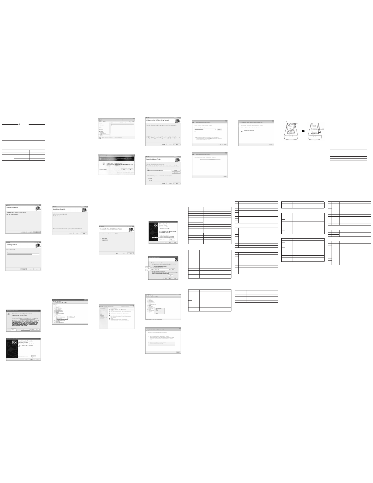
[5] HOW TO CONNECT THE LCR-USB
Make sure that the LCR700 has n either input signal applie d
nor power when conn ecting the LCR-USB to the LCR700.
Attach Ärmly the LCR-USB on the back of th e LCR700.
Connect the USB plug of the communication unit to your PC,
then press the PC button to make it possible to communicate.
[PC] will be shown on the display.
USB opt ical communicat ion unit (LCR-USB )
−19−
• Description of MRE ADH (Block7) / MREADL (Block8)
Bit Name Description
0~7 MREADL 16-bit binary data in the main display
Ex.) MREADH : 2EH, MRE ADL : E3H ==> 12,003
0~7 MREADH
• Description of MSCOPE (Block 9)
Bit Name Description
0
MDOT
Decimal point position (in the main display)
001 : 1999.9, 010 : 199.99
011 : 19.999, 100 : 1.9999
1
2
3
MUNIT
Unit of readings (in the main display)
00000 : None, 00001 : £, 00010 : k£
00011 : M£, 00100: None, 00101 : H
00110 : mH, 00111 : H, 01000 : kH
01001 : pF, 01010 : nF, 01011 : F,
01100 : mF
4
5
6
7
• Description of MSTATUS (Block10)
Bit Name Description
0
MDIS
Contents in the main display
00000 : Number, 00001 : Space,
00010 : Dash
00011 : OL, 00100 : OFF, 00101 : None
00110 : Err, 00111 : Pas s, 01000 : Fail
01001 : Open, 01010 : Short (Sr t)
1
2
3
4
5 MDASH "1" means "----" is shown in the main display.
6 MOL "1" means "OL" is shown in the main display.
7MCNT
The number of counts in the main display
0 : 20000 counts, 1 : 2000 counts
−23−
10-2 Rep air
Customers are asked to provide the following information
when requesting services:
1. Customer name, address, and contact information
2. Description of problem
3. Description of product conÄguration
4. Mo del Number
5. Produ ct Serial Number
6. Proof of Date-of-Purchase
7. Where you purchased the product
Please contact SANWA authorized agent / distributor / service
provider, listed in our website, in your country with above
information. An instrument sent to Sanwa / agent / distributor
without above infor mation will be returned to the customer.
Note:
1) Repair during the warranty period:
The failed unit will be repaired in accordance with the
conditions stipulated in 10-1 Warranty a nd Provision.
2) Repair after the warranty period has expired:
In some cases, repair and transportation cost may
become higher than the price of the product. Please
contact SANWA author ized agent / servic e provider in
advance.
The minimum retenti on period of service functional par ts
is 6 years after the discontinuation of manufacture. This
retention period is the repair warranty period. Please note,
however, if such functional parts become unavailable
for reasons of discontinuation of manufacture, etc., the
retention period may become shorter ac cordingly.
3) Precautions when sending the product to be repaired:
To ensure the safety of the product during transportation,
place the product in a box that is larger than the product 5
times or more in volume and Äll cushion materi als fully and
then clearly mar k “Repair Product Enclosed” on the box
surface. The cost of sending and returning the product
shall be borne by the customer.
10-3 SANWA web site
http://www.sanwa-meter.co.jp
E-mail: exp_sales@sanwa-meter.co.jp
−2−
[2] APPLICATIONS AND FEATURES
2-1 Applications
This application allows you to record the measurements and
date/tim e information to your PC, connecting the handy LCR
meter LCR700 to th e PC.
2-2 Features
• Event re cording available
• Possible to set acquisition intervals the shor test to 59
minutes
• Handling the save d data (CSV format) by a spread sh eet
application make s drawing graphs easy.
[3] INSTALLATION OF LCRLink
3-1 Prepa ration for the inst allation
• Prepa re the bundled installation disc with you.
• Make sure your PC (Per sonal Computer) meets following
minimum hardware requirements.
Minimal: CPU: 1.6 GHz RAM: 1 GB
• Make sure the Operating System on your PC is the English
version of Windows XP, Windows Vista (32 bit), or Windows7
(32 bit/64 bit).
• In the case of Windows XP, Microsoft .NET Framework2.0
or above ha s to be installed in advance. Other wise, visit
Microsoft Download Center to install the .NET Framework.
• Make sure your user account on your PC is an administrator.
• Then insert the install disc into the CD -ROM drive.
−6−
3-8 Completion of Insta llation
The installation has been completed.
Click "Finish" to close the window.
That is all of the installation.
−10−
7) ConÄrmation of the installation Clock "Start" --> "Control
Panel", and open "System". Click the tab "Devic e
Manager". Open the por ts (COM & LPT ), and double-click
"SANWA PC LINK SYSTEM CABLE". Make sure that "This
device is working properly." is s hown on the propert y
window.
−4−
3-4 Welcome to the LC RLink Setup Wizar d
Click "Next".
3-5 Selection of Installation Folder
Click "Nex t" to install in this folder.
−8−
[4] INSTALLATION OF THE DEVICE DRIVER
Do not connect the LCR-USB to the LCR700 when you install
the device driver.
4-1 Installation to Windows XP
1) Start the computer.
2) Put the install disc into the CD -ROM drive. It is assumed
that the CD -ROM drive is assigned as drive E.
3) Inserting LCR-USB to an USB po rt automatically shows
the Found New Hardware Wizard. Select "Install from a
list or sp eciÄc location" and click "Next".
4) A window for specifying a location to search will be
shown. Put a check on "Include this location in the
search", and type "E:\Drive r\XP 32bit" (Dif ferent location
may need to b e typed dependin g on the user's PC.), then
click "Next". Installation of the driver will start.
−12−
5) Open "Other devices" on the Device Manager window,
and you see [USB-Serial Controller] with mark [!], then
right-click to update the driver software.
6) Th e PC will ask you whether you want to search for driver
software automatically or manuall y, and select "manually".
−14−
9) The following window shows the installation has been
complete.
The following example shows COM5 is assigned to the
COM port number.
−18−
• Description of STATUS1 (Block4)
Bit Name Description
0N/AUnused
1N/AUnused
2N/AUnused
3
BAT
Batter y 00 : less than 5 %,
01 : less than 30 %
10 : less than 60 %, 11 : more than 60 %
4
5
FREQ
Measuring frequency
000 : 100 Hz, 001 : 120 Hz, 010 : 1 kHz
011 : 10 kHz, 100 : 100 kHz
6
7
• Description of STATUS2 (Block5)
Bit Name Description
0
SORTP
0011 : ±0.25 %, 0100 : ±0.5 %
0101 : ±1.0 %, 0110 : ±2.0 %
0111 : ±5.0 %, 1000 : ±10.0 %
1001 : ±20.0 %, 1010 : +80 % / -20 %
1
2
3
4N/AUnused
5N/AUnused
6N/AUnused
7N/AUnused
• Description of MMOD3 (Block6)
Bit Name Description
0
MMOD
Mode in the main display
000 : None, 001 : L (Inductance) mod e
010 : C (Capacitance) mode
101 : R (Resistance) mode, 100 : DCR mode
1
2
3N/AUnused
4N/AUnused
5N/AUnused
6N/AUnused
7N/AUnused
−22−
[9] SPECIFICATIONS
Interface
speciÄcation
Compliant with the USB Specification
Rev1.1
Source vo ltage 5 Vdc (from the USB line)
Operating
conditions
Tem per at ur e: 0 〜40 ℃
Humidity: 0 〜80 % (No c ondensation)
Cable length 1.3 m
[10] AFTER-SALE SERVICE
10-1 Warranty and Provision
SANWA offers comprehensive warranty services to its end-
users and to its product resellers. Under SANWA's general
warranty policy, each instrument is warranted to be free from
defects in workmanship or material under normal u se for the
period of one (1) year from the date of purchase.
This war ranty policy is valid within the c ountry of purchase
only, and applied only to the product purchased from Sanwa
authorized agent or distributor.
SANWA rese rves the right to inspect all warranty claims to
determine the extent to which the wa rranty policy shall apply.
This warranty shall not apply to disposables bat teries, or
any product or parts, which have been subj ect to one of the
following causes:
1. A failure due to improper handling or use that deviates from
the instr uction manual.
2. A failure due to inadequate repair or modiÄcation by people
other than Sanwa service personnel.
3. A failure due to causes not attributable to this product such
as Äre, Åood and other natural disaster.
4. Non-operation due to an external power source.
5. A failure or damage due to transportation, relocation or
dropping after the purchase.
−16−
[6] COMMUNICATION SPECIFICATION BETWEEN
LCR700 AND LCR-USB
Users who use the attached communication software LCRLink
do not need to read this section. This section describes the
communication speciÄcation between LCR700 a nd LCR-USB
for users who try to develop a communication software.
Note:
Please n ote that the correct operation in a sof tware you
developed referring to this manual cannot be guaranteed,
and any inquiries cannot be responded.
6-1 Communication method
The LCR-USB is connected as a USB, and the communication
is based o n the RS232C speciÄcation.
The communication method is an asynchronous
communication using a UART (Universal Asynchronous
Receiver Transmitter). This unit is electrically isolated from the
LCR700 using infrared L EDs.
The following shows the details of the port setting.
Baud rate 9600 bps
Data bit 8 bit
Stop bit 1 bit
Parity bit None
Flow control None
Ter min al c ode CR +L F
(0DH+0AH)
6-2 Timing of data transfer
• Transmission timing from the LCR700:
The LCR700 sends data as a re ading on the LCD display is
updated (2 times/sec.) when RTS is active.
−20−
• Description of SMOD3 (Block11)
Bit Name Description
0
SMOD
Mode in the sub display
000 : None, 001 : D (Dissipation factor)
010 : Q (Quality factor)
101 : ESR or Rp (Equiva lent resistance)
100 : θ(Phase angle)
1
2
3N/AUnused
4N/AUnused
5N/AUnused
6N/AUnused
7N/AUnused
• Description of SRE ADH (Blo ck12) / SREADL (Block13)
Bit Name Description
0~7 SREADL 16-bit binary data in the sub display
Ex.) SREADH :1AH, SREADL : B5H ==>6,837
0~7 SREADH
• Description of SSCOPE (Block14)
Bit Name Description
0
SDOT
Decimal point position (in the sub display)
000 : 19999, 001 : 1999.9, 010 : 199.99
011 : 19.999, 100 : 1.9999
1
2
3
SUNIT
Unit of readings (in the sub display)
00000 : None, 00001 : £, 00010 : k£
00011 : M£, 00100 : None, 00101 : H,
00110 : mH, 00111 : H, 01000 : kH,
01001 : pF, 01010 : nF, 01011 : F,
01100 : mF, 01101 : %, 01110 : deg
4
5
6
7


