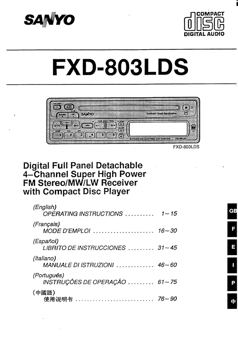
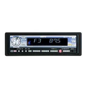
Sanyo FXD-803LD User manual

SERVICE MANUAL DIGITAL FULL PANEL
DETACHABLE 4-CHANNEL
SUPER HIGH POWER
FM STEREO/MW/LW RECEIVER
COMPACT DISC PLAYER
FILE NO.
FXD-803LD
(General)
PRODUCT CODE No.
14782801
Specifications
CD SECTION
D/A Convetier ........................................18Bit Twin
Signal to Noise Ratio .............................95dB
Frequency Response, ............................5-20 .000Hz
Harmonic Distortion ..........................0....0.080/0
Wow& Flutter ........................................Not Measurable
FM TUNER SECTION
Frequency Range .....87...........................87.5 108 MHz
Frequency Response,.,.,., ......................5O-l2.5OOHz
IF Rejection ............................................l OOdB
Image Rejection .....................................65dB
Signalto Noise Ratio .............................6OdB
Stereo Separation ..................................3OdB
MW TUNER SECTION
Frequency Range ..................................522- 1,620 KHz
Usable Sensitivity ...................................35dB
Signal to Noise Ratio .............................45dB
LW TUNER SECTION
Frequency Range ..................................l53.28lkHz
Usable Sensitivity ...................................4Odb
Signalto Noise Ratio .............................4Odb
GENERAL
Power supply .........................................DCl4.4V
Ground polarity ......................................Negative(.)
Frequency Response, ............................2O-20.000Hz
Distotiion ................................................O.l Y0
Output Power(MAX),., ............................25Wx4
RMS Power Rating(l%THD) .,...............9.5WX4
Dimensions(WxHxD) ..............................l9Ox57xl86(mm)
Weight ....................................................l.5kg
—Specifications are subject to change without notice
REFERENCE No. SM800012
NOTES REGARDING THE PICKUP (CD SECTION)
(1) Notes for transport and storage
1)The pickup should always be left in its conductive bag
until immediately prior to use.
2) The pickup should never be subjected to external
pressure or impact.
Storage in conductive bag Drop impact
(2) Re~air notes
‘1)
2)
3)
4)
The pickup incorporates astrong magnet, and so should
never be brought close to magnetic materials.
The pickup should always be handled correctly and
carefully, taking care to avoid external pressure and
impact. If it is subjected to strong pressure or impact, the
result may be an operational malfunction and/or damage
to the printed circuit board,
Each and every pickup is already individually adjusted to
ahigh degree of precision, and for that reason the
adjustment point and installation screws should absolutely
never be touched.
Laser beam may damage the eyes!
Absolutely never permit laser beams to enter the eyes!
Also NEVER switch ON the power to the laser output part
(lens, etc.) of the pickup if it is damaged.
Pressure
4x
4
Pressure
*
o“a
Q- %0
P
.-
5)
Laser Beam
BP
oNEVER look directly at
the laser beam, and don’t
—- Iet contact fingers or other
exposed skin.
Cleaning the lens surface
If there is dust on the lens surface, the dust should be
cleaned away by using an air brush (such as used for
camera lens). The lens is held by adelicate spring.
\
/
How to hold the pickup
Iff
\\, e
Conductive Sheet
6) Never attempt to disassemble the pickup.
–2-

NOTES REGARDING COMPACT DISC PLAYER
1) Preparations
1)
2)
Compact disc players incorporate agreat many ICS as
well as the pickup (laser diode). These components are
sensitive to, and easily affected by, static electricity. If
such static electricity is high voltage, components can be
damaged, and for that reason components should be
handled with care.
The pickup is composed of many optical components and
other high-precision components. Care must be taken,
therefore, to avoid repair of storage where the
temperature of humidity is high, where strong magnetism
is present, or where there is excessive dust.
2) Notes for repair
1)
2)
3)
Before replacing acomponent part, first disconnect the
power supply lead wire from the unit.
All equipment, measuring instruments and tools must be
grounded.
The workbench should be covered with aconductive
sheet and grounded.
When removing the laser pickup from its conductive bag,
do not place the pickup on the bag. (This is because there
is the possibility of damage by static electricity.)
REPAIRS (CD SECTION)
4)
5)
6)
7)
To prevent AC leakage, the metal part of the soldering iron
should be grounded.
Workers should be grounded by an arm band (1MS2).
Care should be taken not to permit the laser pickup to
come in contact with clothing, in order to prevent static
electricity changes in the clothing to escape from the arm
band,
The laser beam from the pickup should NEVER be directly
facing the eyes or bare skin.
A\
h
[Resistor
-(lMfl)
—
/
/1
/
/
Sheet
–3-

-r
--l L..-. -------- ..
1
<
m
w
T_
—
7T
w
C3
l-l
m
cm
cm
0
m
‘$
—,
—,
—
.
I-J
.I
IH
..———
1
6

i
DISASSEMBLY INSTRUCTIONS (CD SECTION)
REMOVING THE PICK UP
1. Remove one spring @from the CD Mechanism F’CB assy
to (Fig. A).
2. Disconnect six lead wires from the CD Mechanism PCB
assy @(Fig. B).
3. Remove the springs SO,I@ (Fig. B).
4. Disconnect two lead wires from the sensor PCB assy (33
(Fig. B).
5. Remove the square belt@ (Fig. B).
6. Remove six machine screws @j (Fig. B).
Tightening torque :2.5Kg
7. Remove the top cover assy.
8. Remove the up lever assy (Fig. C).
9. Remove two springs 63 (Fig. D).
10. Shift the arms @, ~forward (Fig. C).
11. Lift up the pick-up base assy @and remove it from the
damper.
12, Remove two machine screws ‘@~(Fig. D).
.Tightening torque :2Kg
13. Remove the feed plate assy I?4(Fig. D).
14. Remove two machine screws @(Fig. D).
Tightening torque :1 Kg
15. The pick up comes off.
16. Pull off the main pick shaft @(Fig. D).
17. Solder the short pattern on the rear surface of the pick up
(Fig, D).
18. Unlock the connector of the pick up and pull off the pickup
FPC @(Fig. D).
Fig.A
Fig.B
20, Q:J Up lever assy
/
Fig.C
UP
uFig.D
—
-6-

REMOVING THE LIMIT SWITCH
1. Remove one spring @]from the CD Mechanism PCB assy
@(Fig.E)
2. Disconnect two lead wires (brown, green) from the main
PCB assy @Q(Fig. E).
3. Remove one machine screw@ (Fig. F).
Tightening torque :1,5Kg
4. The limit switch assy @comes off (Fig. F).
REMOVING THE FEED MOTOR ASSY
1, Remove one spring 63 from the CD Mechanism PCB assy
‘@ (Fig. A).
2. Disconnect six lead wires from the CD Mechanism PCB
assy @(Fig. A).
3. Remove the springs (50, $2 (Fig. B).
4, Disconnect two lead wires from the sensor PCB assy @Z
(Fig. B).
5, Remove the square belt (a (Fig. B).
6. Remove six machine screws@ (Fig. B).
Tightening torque :2.5Kg
7. Remove the top cover assy.
8. Remove the up lever assy (Fig. C).
9. Remove two springs@ (Fig. D).
10. Shift the arms (?(I,@]forward (Fig. C).
11. Lift up the pick-up base assy to and remove it from the
damper.
12. Remove one machine screw I@ (Fig. G).
Tightening torque :2Kg
13. The feed motor assy @comes off (Fig. G).
XSteps 1to 11 are the same in the REMOVING THE PICK UP.
Fig.E
Fig.F
“@
Fig.G
–7-

DISASSEMBLY (CD SECTION)
REMOVING THE DISC MOTOR ASSY
1,
2.
3.
4,
5.
6.
7.
8.
9.
10.
11.
12.
13.
14,
15.
16.
Remove one spririg @from the CD Mechanism PCB assy
@(Fig. A).
Disconnect six lead wires from the CD Mechanism PCB
assy @(Fig. A).
Remove the springs @, @(Fig. B).
Disconnect two lead wires from the sensor PCB assy @
(Fig. B),
Remove the square belt @(Fig. B).
Remove six machine screws @(Fig. B).
Tightening torque :2.5Kg
Remove the top cover assy.
Remove the up lever assy (Fig. C).
Remove two springs @(Fig. D).
Shift the arms @, @forward (Fig. D).
Lift up the pick-up base assy @and remove it from the
damper.
Remove the springs @, @(Fig. H).
Open the chuck arm assy @by 90”, then lift it up, and
remove (Fig. H).
Align the holes of the disc table @with the locations of the
machine screws @.
Remove the two machine screws @(Fig. H).
Tightening torque :1.8Kg
Slide and remove the disc motor assy @(Fig. H).
XSteps 1to 11 are the same in the REMOVING THE PICK UP
REMOVING THE LOAD MOTOR ASSY
1.
2.
3.
4.
5.
6.
7.
Remove the square belt @)(Fig.1).
Unsolder the load motor assy @at two places (Fig. J).
Unsolder the leaf switch @at two places (Fig.J).
Remove one machine screw @(Fig. J).
Tightening torque :2.5Kg
Slide and remove the main PCB assy @(Fig. J).
Remove one machine screw @(Fig. K).
Tightening torque :2Kg
The load motor assy @comes off (Fig. K).
Fig.H
P
M
Fig.J Fig.K
–8-

REMOVING THE LEAF SWITCH
1. Unsolder the leaf switch@ (Fig, L).
2. Remove the machine screw@ (WU
Tightening torque :1.8Kg
3. The leaf switch @comes off.
-9-

ALIGNMENT PROCEDURES (CD SECTION)
1. NECESSARY EQUIPMENTS FOR ALIGNMENT
0DC power supply :Output OV-20V 1A or more
Tracking power supply xl
Output OV-20V 2A or more
Regular DC power supply xl
@DC volt meter
@Oscilloscope
@Adder amplifier (PART NO. 644006 5456)
@Oscillator
@Test disc (A-BEX TCD-784)
2. BEFORE ALIGNMENT
CD Remove CD Mechanism Control PCB (cD-8 PCB).
@Connect MAIN PCB and CD-8 using the extension cable
(30cm FPC,PART NO. 644006 5463).
CD-8 PCB CN503
Extension Cable
6440065463 ~
6Main PCB
CN602
3. ALIGNMENT
I)FE BIAS ALIGNMENT
Before switching on the power, short TP536 (+5V MAIN)
and TP537 (5VB. UP) using lead wire.
Switch on the power and press RESET switch.
Connect the DC volt meter to TP FEO and TP552
(1/2VCC), and then adjust PT501 until the reading is less
than 0+1 OmV.
Remove the short lead wire.
W552
Vu.%’lm
La
?.
u]
II) FOCUS GAIN ALIGNMENT
Before switching on the power, remove FEO solder and
connect the Adder Amplifier as shown below.
a
(3
(3
c)
~~LIGNMENT PART LOCATION
L
Switch on the power and play the track No.1 of the test
CD.
Connect the oscillator between SG and the ground of the
Adder Amplifier Input the 1.83KHz, -30dB (0.2 Vp-p) sine
save.
Set the oscilloscope to X-Y mode and connect CH1 to X
of the Adder amplifier and CH2 to Y. (Trigger CH1 )
Adjust PT505 (F. GAIN) so that the Lissajous figure can
be as shown below.
m
II1
After adjustment, short FEO solder.
TOP
‘t /DISC SLOT
/
/
t-) 1
1‘T50’‘hd’‘T505J
1LCD Mechanism
Bottom
-1o-

rROUBLESHOOTING (CD SECTION)
Cheak the unit according to the following flowcharl referring to the figures P.24–27.
d
If disc is loaded,
remove the disc by
rotating the loading
ulle toward ou
r’
Check MAIN PCB
8V REG circuit.
Check MAIN PCB
YCheck CD
~Mechanism PCB,
Check loading motor,
N
CheckQ504 &IC507. Replace IC505. Check’
pattern.
CheckCDMechanism
Hg.1k2appearsatTP52?(SEN$1) ~SENSPCB.
CheckSENS1&2,
YCheckD505.
~CheckMAINPCBACC
circuit,
ITv
I I J“ (
+
mIReplace Q505. I
wII
-11–

TROUBLESHOOTING (CD SECTION)
NCheckCN501.
Check~atternbetween
IIC506andCN501,
J,Y
IReplace IC506. I
II
appearsallestpointTP540
YNCheckpatternIC506
fromCN503.
CheckR584.
YCheckFPCI8P.
~CheckCN503FPC
connector.
‘t CheckMAINPCBpattern.
*CheckMAINPCB
microprocessorsolderedpoints.
–12–

@
Replace pickup &
readjustment.
‘f
‘f
I
Clean pickup lens.
Readjust,lfimpossible,
E& =“
‘f RepairCDMechanism,
I1
0Waveformlike
Fig.6appearsat IC503 N
5,6,7pin?
Y
*
Replace IC502.
Check pattern.
Check MAIN PCB
5V AF REG circuit.
Replace IC506. I
Edb
–13–

TROUBLESHOOTING (CD SECTION)
@@
Check R532, R533,
R534, R535.
>Check C539, C540,
C541 ,R542.
MAIN PCB audio
CN503 FPC connector. circuit NG.
Adjust CD
&fast forward is smoothl Mechanism so that
it smoothly operates.
Y
Readjustment. Adjust CD
Mechanism.
c1
Y
Check if the disc
is dirty, defective
or eccentric.
CheckCDMechanismPCB.
+Checkloadingmotor.
Checkloadingmechanism.
JReplace IC505
–14–

ERROR CHART
When any of the error code is displayed on the unit, check the unit according to the following flowchart,
If adisc is loaded,
rotate pulley gear
(No.26) of loading
motor toward voi
and remove d~sc,
I
YCheckCDMechanismPCB.
Check loading motor,
Y
CheckCDMechanlamSENSPCB
Check SENS 1&2.
I---JJ-l
–15-

TROUBLESHOOTING (CD SECTION)
@
N
CheckCDMechanismPCB.
CheckINSW. Check pattern,
NCheckCDMechanismPCB
CheckCHUCKINGswitch.
YCheckCDMechanismPCB.
>Checkloadingmotor
Checkloadingmechanism.
N
L
loading mechanism.
Checkif adiscis caught.
Checkloading/unloading
oerationfive times.
OK
‘t
TP545(UNLOAD)=5V?TP543 4Replace IC505.
IReplace IC506. I
II
–16–

Checkanydefective
Ycircuitin the sled motor
circuit and the CD
Mechanism PCB,
YTN ,
&
NICheck anv defective I
N
switch and the CD
Mechanism PCB.
Check MAIN PCB 5V
CheckMAIN PCBanalog
5V REGcircuit.
–17-

—
TROUBLESHOOTING (CD SECTION)
/3
w
Check the spindle motor.
CheckCDMechanismPCB.
Checkifadisctouchesthe
mechanism.
/
N
o
Focusretrywaveform
likehg,8appearsbetweenTP513 N
andTP5M?
Y
&
Mechanism PCB.
IReplace IC501. I
Over 1.9V
between Q501collector
\
E&El
-18-

Vi%PT501andPT50atcenterposttion Readjust PT501 &
v
Check if adisc is loaded
upside down,
Check if adisc is dirty or
defective,
Checkany defective
circuitinPickupFPC.
CheckifCN502properly
solderedandconnected,
ReplaceIC501andIC502,
J?Y
TRACKbalance
wavelormofTP553appears N
symmetricallywithO
alcenter?
Y
Check
IiadiscISdirtyordelective,
Check sled driving Checkifthe@ckuplensisdirty,
Check&replaceIC501,
IC502,IC506,
Checkpickup.
Checkanydefectivecircuit
in PickupFPC,
m
–19-

TROUBLESHOOTING (CD SECTION)
[Error’ sign L-En’)
waveformlikeFig.3appears
Check R584.
Check PCB pattern
N
----LY-
Check MAIN PCB
microprocessor.
Replacemicroprocessor
of MAINPCB.
Reference waveforms
Check 18P FPC.
●Check CN503
soldered point.
*
ommuncallonImmnals01ManPCB
I1III I IIII1
r’” J
1
-1
oil 5V C42 5V A0.2 s
LY3 5VI1,ROL ,II I
Fig.1
CH1
CH2
Mode:
TP529 SENS 1
TP517 SENS 2
When the 12cm CD is being loaded.
-20-

Figures
II[I I IIII
Trig i- 1.6div
L-J---Ii
ml 5V 012 5V Aa2s
pu ,5vII,ROLI I I I
Fig.2
IIIII I I 11
Trig +0. Odiv
1
tL ......
t——————i
r
WI 5V rli2 5V AEs
,p+? ,5 vII,30LI [ I I
Fig.3
I,,, Ill
Trig +(). odiv
t
IIII
‘“l
-1
A5ms i
,STOI IIII
CH1
CH2
CH3
Mode:
CH1
CH2
CH3
CH1
Mode:
TP529 SENS 1
TP517 SENS 2
TP527 CHUCK SW
When the 8cm CD is being loaded.
TP538 ACC
TP536 +5V Main
TP540 DATA (CONT)
When the disk is loaded and the power is on.
.-
A(CONT)
When power is on.
Table of contents
Other Sanyo Car Receiver manuals

Sanyo
Sanyo FXCD-550 - Radio / CD User manual

Sanyo
Sanyo FX-02 User manual

Sanyo
Sanyo AVC-100 User manual

Sanyo
Sanyo CDF-R800 User manual

Sanyo
Sanyo CDF-R800 User manual

Sanyo
Sanyo FXR-45GD User manual

Sanyo
Sanyo FXCD-500 User manual

Sanyo
Sanyo MAR-B1021 User manual

Sanyo
Sanyo FXC-425GD User manual

Sanyo
Sanyo cdf-30 User manual

Sanyo
Sanyo ECD-T1560 Instruction and safety manual

Sanyo
Sanyo FXCD-550 - Radio / CD User manual

Sanyo
Sanyo EX-600 User manual

Sanyo
Sanyo FXR-100LD User manual

Sanyo
Sanyo MCX-400 User manual

Sanyo
Sanyo FXCD-1350 - Radio / CD User manual

Sanyo
Sanyo MAR-1000 (A) User manual

Sanyo
Sanyo CDF-R800 User manual

Sanyo
Sanyo FXD-RR1 User manual

Sanyo
Sanyo CDF-201G User manual