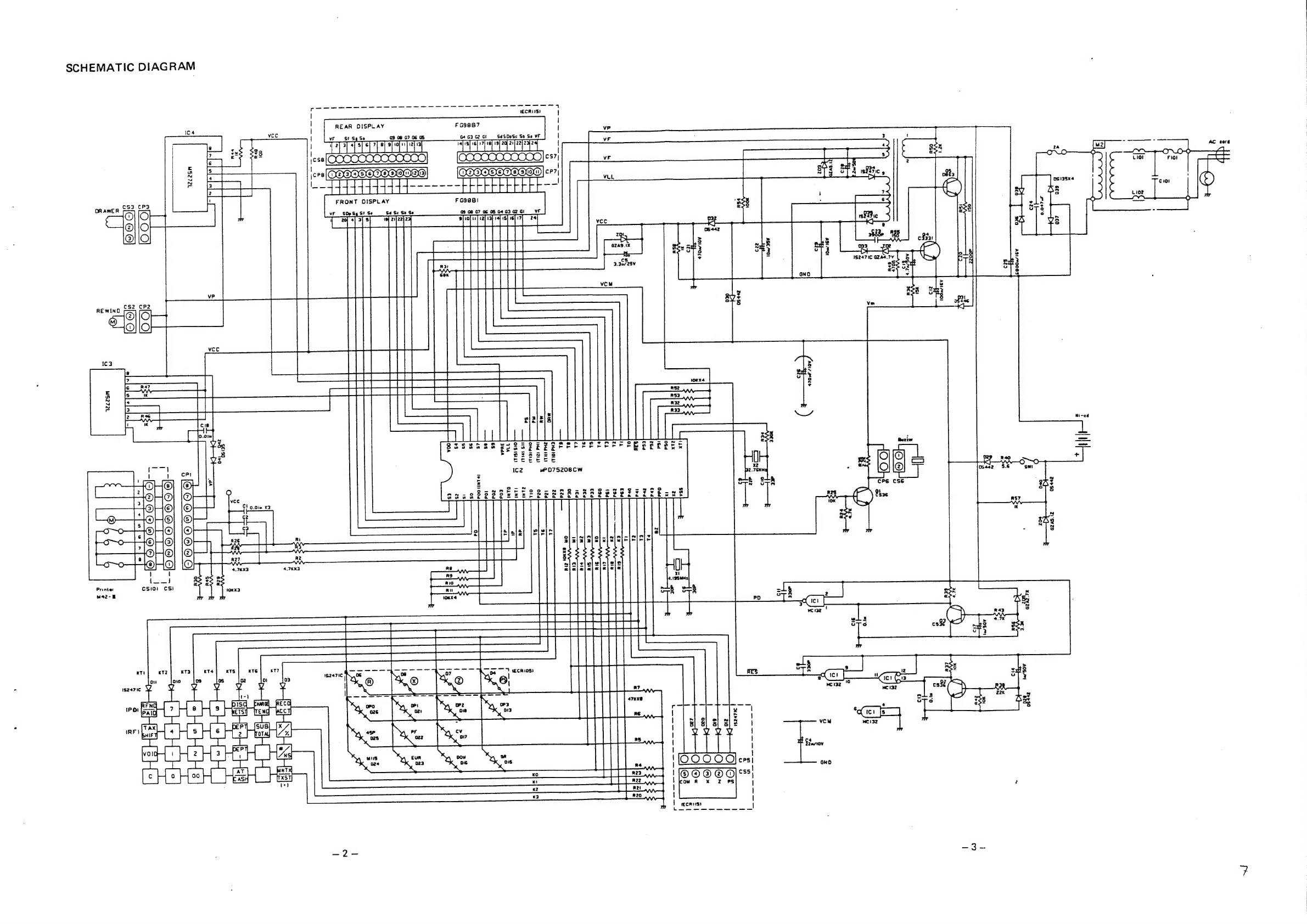
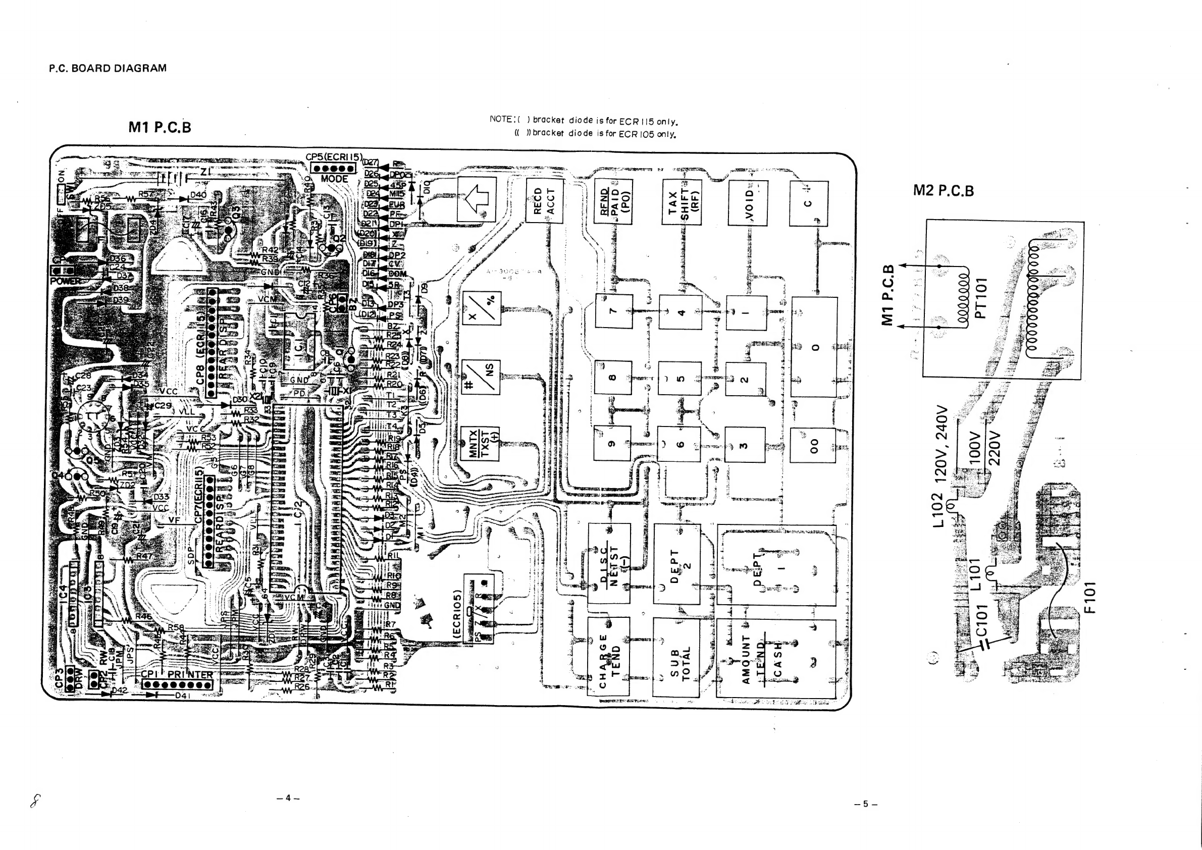
Sanyo ECR105 User manual
Other Sanyo Cash Register manuals


Popular Cash Register manuals by other brands


Sharp
Sharp XE-A137-WH Operation Basic user manual

Sharp
Sharp XE-A203 - Cash Register Thermal Printing Graphic Logo... instruction manual

TEC
TEC TEC MA-1060 owner's manual

Casio
Casio PCR-408 Operator's instruction manual

ELCOM
ELCOM Euro-2100TE user manual

American Changer
American Changer CLASSIC Series Operation manual