In the area emitting the highest reading, switch the meter
to SLOW RESPONSE, and take a reading for minimum of
three (3) seconds. We recommended the pattern outline
shown below when the door surface is surveyed.
NOTE : Periodically check to be sure that the probe tip is
not worn or dirty.
The following U.S. standard applies to microwave ovens :
21 CFR 1030.10, Performance Standard for Microwave
Ovens.
It requires that the power density of the microwave
radiation emitted by a microwave oven shall not exceed
five (5) milliwatts per square centimeter at any point 5
centimeter (about 2 inches) or more from the external
surface of the oven.
All microwave ovens exceeding the emission level of
4mW/cm2must be reported to Dept. of Service for
microwave ovens and the manufacturer immediately and
the owner should be told not to use the microwave oven
until it has been repaired completely.
If a microwave oven is found to operate with the door open,
report to Dept. of Service, the manufacturer and CDRH*
immediately. Also tell the owner not to use the oven.
*CDRH : Center for Device and Radiological Health.
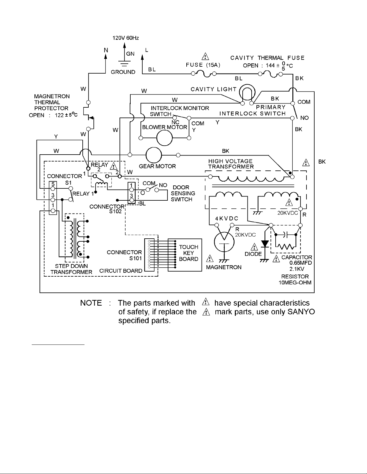
The interlock monitor switch acts as the final safety switch
protecting the customer from microwave radiation. If the
interlock monitor switch operates to blow the fuse with
interlocks failed, you must replace all interlock switches
primary and secondary interlock switches and the monitor
switch with new ones because the contacts of those
interlock switches may be melted and welded together.
CAUTIONCAUTION
CAUTIONCAUTION
CAUTION
For micrFor micr
For micrFor micr
For microwave enerowave ener
owave enerowave ener
owave energy emissiongy emission
gy emissiongy emission
gy emission
On every service calls, check for microwave energy
emission, must be made according to the following manner.
MeasurMeasur
MeasurMeasur
Measurement of enerement of ener
ement of enerement of ener
ement of energy emissiongy emission
gy emissiongy emission
gy emission
Measurement must be made with the microwave oven
operating at its maximum output and containing a load of
275±15 milliliters of tap water initially at 20o±5ocelsius (68
±9oF) placed within the cavity at the center.
NOTE : The water container must be a 600 milliliter beaker
and made of an electrically none conductive
material such as glass or plastic.
The cook tray must be in place when measuring
emission.
A properly operating door and seal assembly will normally
register emission on greater than 4mW/cm2 to allow for
measurement uncertainty with the cooking shelf or tray in
place.
All repairs must be performed in such a mannerAll repairs must be performed in such a manner
All repairs must be performed in such a mannerAll repairs must be performed in such a manner
All repairs must be performed in such a manner thatthat
thatthat
that
micrmicr
micrmicr
microwave enerowave ener
owave enerowave ener
owave energy emission argy emission ar
gy emission argy emission ar
gy emission are minimal.e minimal.
e minimal.e minimal.
e minimal.
Follow the instructions supplied with a detector being used
and performed an R.F. emission test around the door front
and edges and all edges and vent of the outer case. The
cabinet (wrapper) must be in place and the oven fully
assembled.
When performing emission survey, with the meter on FAST
RESPONSE the movement of a detector probe shall not
exceed one (1) inch per second.
- i -


M Service manual")